Kubota V3800-CR-TE4B V3800-CR-TIE4B Common Rail System Diagnosis Manual – PDF DOWNLOAD
Original price was: $89.95.$30.95Current price is: $30.95.
Kubota V3800-CR-TE4B V3800-CR-TIE4B Common Rail System Diagnosis Manual – PDF DOWNLOAD
Description
Kubota V3800-CR-TE4B V3800-CR-TIE4B Common Rail System Diagnosis Manual – PDF DOWNLOAD
DESCRIPTION:
Kubota V3800-CR-TE4B V3800-CR-TIE4B Common Rail System Diagnosis Manual – PDF DOWNLOAD
SAFETY WORKING :
• Do not work on the machine while under the
influence of alcohol, medication, or other substances
or while fatigued.
• Wear close fitting clothing and safety equipment
appropriate to the job.
• Use tools appropriate to the work. Makeshift tools,
parts, and procedures are not recommended.
• When servicing is performed together by two or more
persons, take care to perform all work safely.
• Do not touch the rotating or hot parts while the
engine is running.
• Never remove the radiator cap while the engine is
running, or immediately after stopping. Otherwise,
hot water will spout out from radiator. Only remove
radiator cap when cool enough to touch with bare
hands. Slowly loosen the cap to first stop to relieve
pressure before removing completely.
• Escaping fluid (fuel or hydraulic oil) under pressure
can penetrate the skin causing serious injury.
Relieve pressure before disconnecting hydraulic or
fuel lines. Tighten all connections before applying
pressure.
• Wear a suitable hearing protective device such as
earmuffs or earplugs to protect against objectionable
or uncomfortable loud noises.
• Do not open high-pressure fuel system.
High-pressure fluid remaining in fuel lines can cause
serious injury. Do not disconnect or attempt to repair
fuel lines, sensors, or any other components
between the high-pressure fuel pump and injectors
on engines with high pressure common rail fuel
system.
• High voltage exceeding 100 V is generated in the
ECU and injector.
Pay sufficient caution to electric shock when
performing work activities.
TABLE OF CONTENTS:
Kubota V3800-CR-TE4B V3800-CR-TIE4B Common Rail System Diagnosis Manual – PDF DOWNLOAD
I INFORMATION 2
INFORMATION 3
1 SAFETY FIRST 4
1 COMMON RAIL SYSTEM 7
MECHANISM 8
1 BASIC SYSTEM INFORMATION 9
[1] SYSTEM CONFIGURATION 9
[2] FUEL SYSTEM 10
[3] INTAKE AND EXHAUST SYSTEM 11
[4] AVAILABLE DATA MONITOR SIGNALS (LEVEL 1) 12
(1) Monitor Items 12
(2) Normal Value 15
[5] ECU TERMINAL LAYOUT 18
(1) ECU Terminal Layout 1 (Engine Side) 18
(2) ECU Terminal Layout 2 (Machine Side) 21
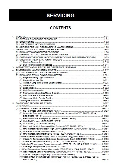
SERVICING 24
1 GENERAL 27
[1] OVERALL DIAGNOSTIC PROCEDURE 27
[2] QUESTIONING 28
[3] LIST OF MALFUNCTION SYMPTOM 31
[4] ACTIONS FOR NON-REOCCURRING MALFUNCTIONS 32
2 DIAGNOSTIC TOOL CONNECTION PROCEDURE 34
[1] DIAGNOSTIC CONNECTOR POSITIONS 34
[2] DIAGNOSTIC TOOL CONNECTION PROCEDURE 34
[3] CHECKING THE COMMUNICATION OPERATION OF THE INTERFACE (DST-i) 35
[4] CHECKING THE OPERATION OF THE ECU 36
(1) Starting Diagmaster 36
(2) DST-i Communication Settings 37
3 ACTIVE TEST AND SUPPLY PUMP DIFFERENCE LEARNING 41
4 DIAGNOSIS BY MALFUNCTION SYMPTOM 43
[1] LIST OF MALFUNCTION CAUSES BY SYMPTOM 43
[2] DIAGNOSIS BY MALFUNCTION SYMPTOM 47
(1) Engine Warning Light Comes On 47
(2) Engine Does Not Start 47
(3) Takes A Long Time Before Engine Starts 51
(4) Idle Failure 55
(5) Engine Noise 58
(6) High fuel consumption 60
(7) Poor Acceleration (Insufficient Output) 65
(8) Abnormal Black Smoke Emitted 70
(9) Abnormal White Smoke Emitted 74
(10) Engine Stalls On Deceleration 79
5 DIAGNOSTIC PROCEDURE BY DTC 83
[1] DTC LIST 83
[2] DIAGNOSTIC PROCEDURE BY DTC149
(1) NE – G Phase Shift (DTC P0016 / 636-7)153
(2) Intake Air Temperature Built-in MAF Sensor: Abnormality (DTC P0072 / 171-4, DTC P0073 / 171-3)154
(3) Pressure Limiter Emergency Open (DTC P0087 / 633-7)157
(4) High Rail Pressure (DTC P0088 / 157-0)162
(5) SCV Stuck (DTC P0089 / 1347-7)167
(6) Fuel Leak (in High Pressured Fuel System) (DTC P0093 / 1239-1)172
(7) MAF Sensor Power Supply: High (24 V-System Only) (DTC P0100 / 132-16)177
(8) Intake Air Volume: Low (DTC P0101 / 132-1)179
(9) MAF Sensor Abnormality (DTC P0102 / 132-4, P0103 / 132-3)180
(10) MAF Sensor Power Supply: Low (24 V-System Only) (DTC P0104 / 132-18)182
(11) Intake Air Temperature: High (Inter Cooler Model Only) (DTC P0111 / 172-0)184
(12) Intake Air Temperature Error (DTC P0112 / 172-4, P0113 / 172-3)185
(13) Coolant Temperature Sensor Abnormality (DTC P0117 / 110-4, P0118 / 110-3)188
(14) Fuel High Temperature (DTC P0181 / 174-0)191
(15) Fuel Temperature Sensor Abnormality (DTC P0182 / 174-4, P0183 / 174-3)192
(16) Rail Pressure Sensor Abnormality (DTC P0192 / 157-4, P0193 / 157-3)195
(17) Injector Charge Voltage: High (DTC P0200 / 523535-0)199
(18) Open Circuit of Harness/Coil (DTC P0201 / 651-3, P0202 / 653-3, P0203 / 654-3, P0204 / 652-3)201
(19) Engine Overheat (DTC P0217 / 110-0)204
(20) Engine Overrun (DTC P0219 / 190-0)206
(21) Boost Pressure Sensor Abnormality (DTC P0237 / 102-4, P0238 / 102-3)207
(22) Crankshaft Position Sensor (NE Sensor) Abnormality (DTC P0335 / 636-8, P0336 / 636-2)211
(23) Camshaft Position Sensor (G Sensor) Abnormality (DTC P0340 / 723-8, P0341 / 723-2)216
(24) Air Heater Relay Driving Circuit Abnormality (DTC P0380 / 523544-3 / 523544-4)220
(25) EGR Actuator Abnormality (DTC P0403 / 523574-3, DTC P0404 / 523574-4, P0409 / 523572-4)223
(26) Oil Pressure Error (P0524 / 100-1)226
(27) Exhaust Gas Temperature Sensor 1 (T1) Abnormality (DTC P0543 / 3242-4, P0544 / 3242-3)228
(28) Exhaust Gas Temperature Sensor 0 (T0) Abnormality (DTC P0546 / 4765-4, P0547 / 4765-3)231
(29) Battery Voltage Abnormality (DTC P0562 / 168-4, P0563 / 168-3)234
(30) QR Data Abnormality (DTC P0602/523538-2, P0602/523538-7)237
(31) ECU Flash-ROM and CPU Abnormality (DTC P0605 / 628-2, P0606 / 1077-2, P0606/ 523527-2)238
(32) Injector Charge Voltage Abnormality (DTC P0611 / 523525-1)240
(33) SCV Drive System Abnormality (DTC P0628 / 1347-4, P0629 / 1347-3)242
(34) Sensor Supply Voltage 1 Abnormality (DTC P0642 / 3509-4, P0643 / 3509-3)246
(35) Sensor Supply Voltage 2 Abnormality (DTC P0652 / 3510-4, P0653 / 3510-3)248
(36) Sensor Supply Voltage 3 Abnormality (DTC P0662 / 3511-4, P0663 / 3511-3)250
(37) Sensor Supply Voltage 4 Abnormality (DTC P0672 / 3512-4, P0673 / 3512-3)252
(38) Main Relay is Locked in Closed Position (DTC P0687 / 1485-2)254
(39) Pump Seizing (DTC P1274 / 523539-2, P1275 / 523540-2)257
(40) EEPROM Check Sum Error (DTC P1990 / 523700-13)262
(41) Intake Throttle Feedback Error (DTC P2108 / 523580-2)263
(42) Accelerator Position Sensor 1 Abnormality (DTC P2122 / 91-4, P2123 / 91-3)265
(43) Accelerator Position Sensor 2 Abnormality (DTC P2127 / 29-4, P2128 / 29-3)269
(44) Accelerator Position Sensor Error (CAN) (DTC P2131 / 523543-2)273
(45) Accelerator Position Sensor Correlation Error (DTC P2135 / 91-2)275
(46) Common 1 System Injector Drive Circuit Open (DTC P2146 / 523523-2)276
(47) Common 1 TWV Actuation System Short (DTC P2147 / 523523-4, P2148 / 523523-3)279
(48) Common 2 System Injector Drive Circuit Open (DTC P2149 / 523524-2)283
(49) Common 2 TWV Actuation System Short (DTC P2150 / 523524-4, P2151 / 523524-3)286
(50) Barometric Pressure Sensor Error (DTC P2228 / 108-4, P2229 / 108-3)290
(51) EGR (DC Motor) Abnormality (DTC P2413 / 523575-7, P2414 / 523576-2, P2415 / 523577-2)292
(52) Exhaust Gas Temperature Sensor 2 (T2) Abnormality (DTC P242C / 3246-4, P242D / 3246-3)295
(53) Differential Pressure Sensor 1 Abnormality (DTC P2454 / 3251-4, P2455 / 3251-3)298
(54) Intake Throttle Lift Sensor Abnormality (DTC P2621 / 523583-4, P2622 / 523582-3)302
(55) Emission Deterioration (DTC P3001 / 3252-0)304
(56) Exhaust Gas Temperature Sensor 0: Emergency High (DTC P3002 / 4765-0)306
(57) Exhaust Gas Temperature Sensor 1: Emergency High (DTC P3003 / 3242-0)308
(58) Exhaust Gas Temperature Sensor 2: Emergency High (DTC P3004 / 3246-0)310
(59) Excessive PM3 (DTC P3006 / 3701-15)312
(60) Excessive PM4 (DTC P3007 / 3701-16)313
(61) Excessive PM5 (DTC P3008 / 3701-0)314
(62) Boost Pressure Low (DTC P3011 / 132-15)315
(63) Low Coolant Temperature in Parked Regeneration (DTC P3012 / 523589-17)317
(64) Parked Regeneration Time Out (DTC P3013 / 523590-16)318
(65) All Exhaust Gas Temperature Sensor Failure (DTC P3018 / 523599-0)320
(66) Initial Pump-calibration Incomplete (DTC P3019 / 523600-0)321
(67) High Exhaust Gas Temperature After Emergency High Temperature DTC (DTC P3023 / 523601-0)322
(68) High Frequency of Regeneration (DTC P3024 / 523602-0)323
(69) Over Heat Pre-caution (DTC P3025 / 523603-15)324
(70) CAN2 Bus Off (DTC U0075 / 523547-2)325
(71) No Communication with EGR (DTC U0076 / 523578-2)327
(72) CAN1 Bus Off (DTC U0077 / 523604-2)329
(73) CAN2 Frame Error (DTC U0081 / 523548-2, U0082 / 523591-2, U0083 / 523592-2, U0084 / 523593-2, U0085 / 523594-2, U0086 / 523595-2, U0087 / 523596-2, U0089 / 523598-2)330
6 INSPECTION PROCEDURE FOR EACH SYSTEM334
[1] AIR INTAKE SYSTEM INSPECTION PROCEDURE334
[2] FUEL SYSTEM INSPECTION PROCEDURE335
[3] ELECTRIC SYSTEM INSPECTION PROCEDURE340
(1) Basics Of Checking Electrical / Electronic Circuit Systems340
(2) Connector Connection Fault Verification Method343
(3) Checking The Power And Ground System (Main Relay, ECU Circuit)344
IMAGES PREVIEW OF THE MANUAL:
KUBOTA V3800-CR-TE4B V3800-CR-TIE4B COMMON RAIL SYSTEM DIAGNOSIS MANUAL – PDF DOWNLOAD:
PLEASE NOTE:
- This is the same manual used by the DEALERSHIPS to SERVICE your vehicle.
- The manual can be all yours – Once payment is complete, you will be taken to the download page from where you can download the manual. All in 2-5 minutes time!!
- Need any other service / repair / parts manual, please feel free to contact us at heydownloadss @gmail.com . We may surprise you with a nice offer
S.V