Land Rover AJ133 5.0L V8 NA/SC ON BOARD DIAGNOSTIC Manual PDF
$28.95
Land Rover AJ133 5.0L V8 NA/SC ON BOARD DIAGNOSTIC Manual – PDF DOWNLOAD
Description
Land Rover AJ133 5.0L V8 NA/SC ON BOARD DIAGNOSTIC Manual – PDF DOWNLOAD
FILE DETAILS:
Land Rover AJ133 5.0L V8 NA/SC ON BOARD DIAGNOSTIC Manual – PDF DOWNLOAD
Language : English
Pages : 242
Downloadable : Yes
File Type : PDF
IMAGES PREVIEW OF THE MANUAL:
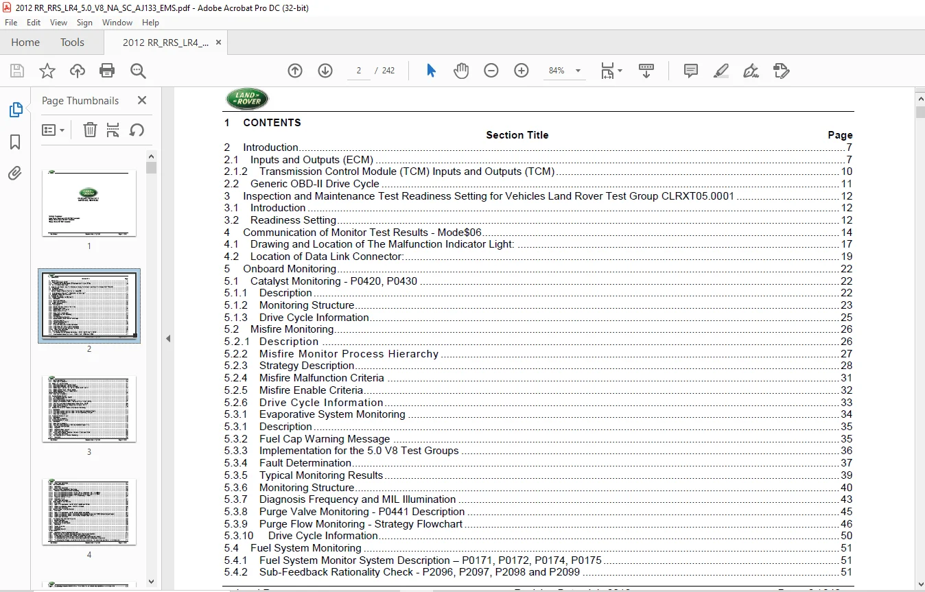
TABLE OF CONTENTS:
Land Rover AJ133 5.0L V8 NA/SC ON BOARD DIAGNOSTIC Manual – PDF DOWNLOAD
2 Introduction7
21 Inputs and Outputs (ECM) 7
212 Transmission Control Module (TCM) Inputs and Outputs (TCM) 10
22 Generic OBD-II Drive Cycle 11
3 Inspection and Maintenance Test Readiness Setting for Vehicles Land Rover Test Group CLRXT050001 12
31 Introduction 12
32 Readiness Setting12
4 Communication of Monitor Test Results – Mode$0614
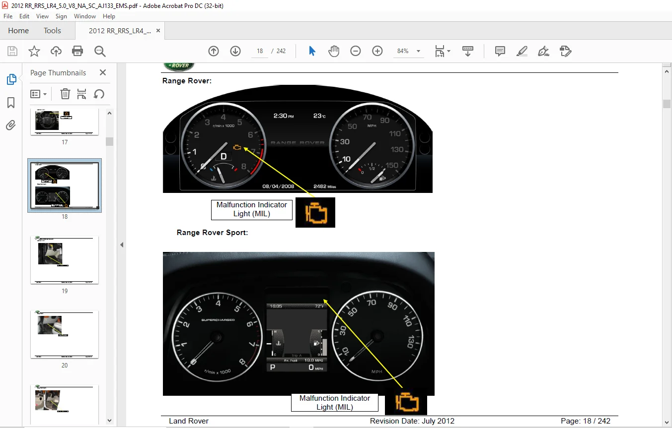
41 Drawing and Location of The Malfunction Indicator Light: 17
42 Location of Data Link Connector:19
5 Onboard Monitoring22
51 Catalyst Monitoring – P0420, P0430 22
511 Description22
512 Monitoring Structure23
513 Drive Cycle Information25
52 Misfire Monitoring26
521 Description 26
522 Misfire Monitor Process Hierarchy 27
523 Strategy Description28
524 Misfire Malfunction Criteria 31
525 Misfire Enable Criteria32
526 Drive Cycle Information33
531 Evaporative System Monitoring 34
531 Description35
532 Fuel Cap Warning Message 35
533 Implementation for the 50 V8 Test Groups 36
534 Fault Determination37
535 Typical Monitoring Results 39
536 Monitoring Structure40
537 Diagnosis Frequency and MIL Illumination 43
538 Purge Valve Monitoring – P0441 Description 45
539 Purge Flow Monitoring – Strategy Flowchart 46
5310 Drive Cycle Information50
54 Fuel System Monitoring 51
541 Fuel System Monitor System Description – P0171, P0172, P0174, P0175 51
542 Sub-Feedback Rationality Check – P2096, P2097, P2098 and P2099 51
Land Rover Revision Date: July 2012 Page: 3 / 242
543 Monitoring Structure52
544 Drive Cycle Information56
55 Oxygen Sensor Monitoring 57
551 HAFS Slow Response – P0133, P015357
552 HAFS Slow Activation – P0134 and P0154 64
553 HEGO High or Low Monitor – P0137, P0138, P0157, P015866
554 HEGO Activity Check – P0140, P0160 71
555 HEGO Response Check – P0139, P0159 74
Oxygen Sensor Monitoring 85
556 Drive Cycle Information91
56 Cooling System Monitors 92
561 Thermostat Monitoring – P012892
562 General Description 93
563 Coolant Temperature Sensor Monitors 95
564 Range or Performance Failure – P0116 (ECT1) or P2183 (ECT2)97
565 Time to Closed Loop Fuelling Enable Temperature – P0125 100
566 Highest Minimum Enable Temperature Achieved – P0126 102
567 Drive Cycle Information110
57 Positive Crankcase Ventilation (PCV) System Monitoring 111
571 Description111
572 PCV Valve Location and Hose Layout for the Naturally Aspirated Engine112
573 PCV Valve Location and Hose Layout for the Supercharged Engine 113
574 Drive Cycle Information114
58 Crankshaft Position Sensor 115
581 Description115
582 Drive Cycle Information116
59 Camshaft Position Sensors116
591 Description116
592 Drive Cycle Information117
510 Camshaft Profile Switching – Naturally Aspirated Engine Only 118
5101 Schematic and Operation 118
5102 Diagnosis 119
5103 Diagnostic Measurement: 121
5104 Drive Cycle Information125
511 Air-Fuel Ratio Cylinder Imbalance Monitor – P219A and P219B125
5111 Drive Cycle Information138
512 Cold Start Emission Reduction Monitoring139
5121 Description139
Land Rover Revision Date: July 2012 Page: 4 / 242
5122 Drive Cycle Information147
513 Idle Speed Control 148
5131 Description148
5132 Drive Cycle Information149
514 Comprehensive Component Monitoring150
5141 Air Intake Temperature Sensor Monitoring 150
5142 Intake Air Temperature Sensor – Stuck in Range Diagnostic – P0111 & P00AB151
5143 Intake Air Temperature Sensor – Biased Sensor Diagnostic – P0111 & P00AB153
5144 Intake Air Temperature Sensor 2 – Post-Supercharger – P007B155
5145 Range/Performance Check157
5146 Rationality Check 157
5147 Drive Cycle Information164
515 Mass Airflow Sensor Monitors165
5151 Schematic 165
5152 High or low input failure – P0102, P0103, P010C and P010D165
5153 Range or performance failure – P0101 and P010B 165
5154 Drive Cycle Information176
516 Manifold Pressure Sensor Monitors 177
5161 Schematic 177
5162 High or low input failure – P0107, P0108, P0237 and P0238 178
5163 Range or performance failure – P0106 (Naturally Aspirated Engine) and P0236 (Supercharged Engine) 178
5164 Range or performance failure – P0106 (Supercharged Engine only) 180
5165 Drive Cycle Information186
517 Fuel Injector Operation and Diagnosis186
5171 Injector Operation 186
5172 Drive Cycle Information189
518 Transmission Control Module 190
5181 Description190
5182 Torque Converter193
5183 Description193
5184 Monitoring Structure193
Torque Converter193
5185 Electronic Pressure Regulator Solenoids194
519 Parameters and Conditions Necessary to Begin Closed Loop Operation213
5191 Closed loop fuel control will be started if the following are true:213
5192 The following faults will be detected, if the criteria to go closed loop are not met: 214
5193 The following conditions will cause closed loop control of the fuelling to be suspended: 214
5194 The following front Oxygen sensor faults will result in a failure to enter closed loop operation or in its suspension: 215
Land Rover Revision Date: July 2012 Page: 5 / 242
5195 The following component faults will result in a failure to enter closed loop operation or in its suspension: 215
520 Knock Sensor216
5201 Description216
5202 Drive Cycle Information217
521 ECM Power Supplies 217
5211 Description217
5212 Drive Cycle Information217
522 Engine Control Module Self Test 218
5221 Description218
5222 Drive Cycle Information219
523 Engine Starting 220
5231 Crank Request Signal 220
5232 Park / Neutral Switch 220
5233 Starter Relay220
5234 Drive Cycle Information222
524 Accelerator Pedal Position Sensor222
5241 Description222
5242 Drive Cycle Information223
525 Throttle Control System 224
5251 Description224
5252 Drive Cycle Information226
526 Torque Monitoring227
5261 Description227
5262 Drive Cycle Information227
527 Ignition Amplifiers / Coils228
5271 Description228
5272 Drive Cycle Information228
528 Variable Valve Timing 229
5281 Hardware Check 229
5282 Camshaft Position229
5283 Drive Cycle Information232
529 Controller Area Network System233
5291 Monitoring Structure233
5292 TCM Gear Selector Communications Monitoring237
5293 Drive Cycle Information237
530 Fuel Level Sensor 238
5301 Drive Cycle Information238
531 Engine Off Timer239
Land Rover Revision Date: July 2012 Page: 6 / 242
5311 Description239
5312 Drive Cycle Information240
532 Supercharger Intercooler Water Pump 241
5321 Drive Cycle Information241
533 High Range Enablement 242
5331 Drive Cycle Information242
S.V 28/02/2025