Land Rover Discovery Series II Technical Academy Brochure Manual – PDF DOWNLOAD
Original price was: $89.95.$28.95Current price is: $28.95.
Land Rover Discovery Series II Technical Academy Brochure Manual – PDF DOWNLOAD
Description
Land Rover Discovery Series II Technical Academy Brochure Manual – PDF DOWNLOAD
DESCRIPTION:
Land Rover Discovery Series II Technical Academy Brochure Manual – PDF DOWNLOAD
INTRODUCTION:
- The first Land Rover vehicle was revealed to the public at the Amsterdam Motor Show in
1948. It was designed to address the demanding and specialist needs of the utility market,
which was at the time, dominated by farmers and military users. - Since then, the company has developed its model range carefully in a controlled and deliberate
manner, and has influenced heavily the significant growth of the 4×4 market. Land Rover has
generated a reputation for the design and production of four wheel drive vehicles that is second
to none. - This reputation has been built on a small but impressive range of vehicles which have
earned almost icon status within their respective market niches.
IMAGES PREVIEW OF THE MANUAL:
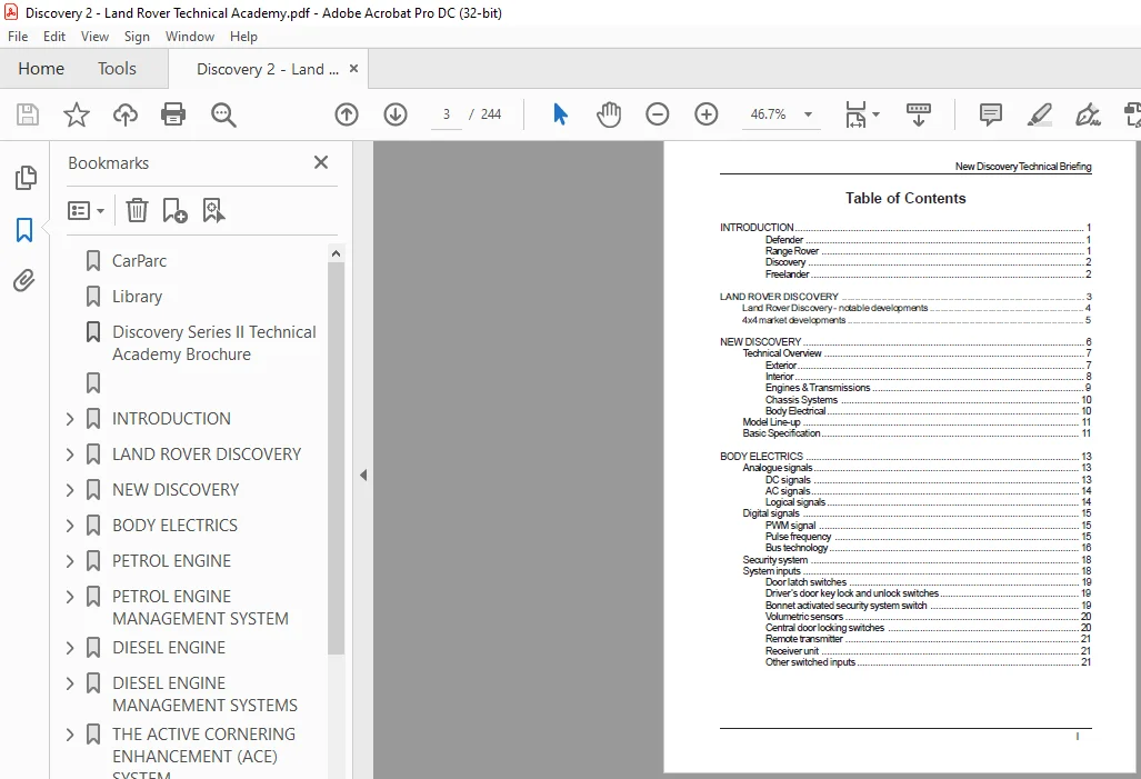
TABLE OF CONTENTS:
Land Rover Discovery Series II Technical Academy Brochure Manual – PDF DOWNLOAD
INTRODUCTION 1
Defender 1
Range Rover 1
Discovery 2
Freelander 2
LAND ROVER DISCOVERY 3
Land Rover Discovery – notable developments 4
4×4 market developments 5
NEW DISCOVERY 6
Technical Overview 7
Exterior 7
Interior 8
Engines & Transmissions 9
Chassis Systems 10
Body Electrical 10
Model Line-up 11
Basic Specification 11
BODY ELECTRICS 13
Analogue signals 13
DC signals 13
AC signals 14
Logical signals 14
Digital signals 15
PWM signal 15
Pulse frequency 15
Bus technology 16
Security system 18
System inputs 18
Door latch switches 19
Driver’s door key lock and unlock switches 19
Bonnet activated security system switch 19
Volumetric sensors 20
Central door locking switches 20
Remote transmitter 21
Receiver unit 21
Other switched inputs 21
System outputs 22
BCU 22
Intelligent driver’s module 23
Door lock actuators 23
Passive coil 24
Battery backed sounder 24
Vehicle horn 24
Alarm horn 24
Hazard lamps 24
Security system status LED 25
Starter relay 25
Fuel flap release switch/actuator 26
Courtesy lamps 26
Headlamps 27
System operation 27
Locking 27
Unlocking 28
Market dependent security features 28
Perimetric protection 29
Volumetric protection 30
Superlocking 31
Mislock function 31
Partial arming 32
Passive immobilisation 32
Passive remobilisation 32
Emergency key access 33
Single point entry 34
Speed related locking 34
Bathrobe locking 35
Courtesy headlamps 35
Security system LED 35
Courtesy lights 36
Transit mode 36
Market programming and customer configuration 37
Non-CLASS options 38
CLASS options 40
Wiper system 42
Front wiper speed I, II and flick 42
Front wipers intermittent operation 43
Front and rear windscreen programmed wash 44
Headlamp power wash 44
Rear window wipe 45
Reverse gear wipe 45
Front and rear fog lamps 46
Daylight running lamps 46
Instrument pack 47
Dials 48
Driver information lamps 49
LCD display 51
Sounder 53
Fuel contamination monitoring system 53
Windows and sunroof inputs 53
Electric Windows and Sunroof Block Diagram 54
Ignition switch 55
Front window console switches 55
Rear window console switches and rear door switches 55
Rear window disable switch 56
Sunroof switches 56
Rear sunroof isolator switch 56
Sunroof micro-switches 57
Windows and sunroof outputs 57
Front window lift motors 57
Sunroof motors 57
Window operation 58
One-touch function 58
Time-out function 59
Rear window and sunroof operation 59
In car entertainment 60
New features 61
Audio power amplifier 61
Rear headphone modules 63
Premium head unit 64
Climate control system 65
Automatic temperature control (ATC) 66
Solar sensor 66
Ambient temperature sensor 66
Interior temperature sensor 66
Coolant temperature sensor 67
Evaporator sensor 67
Condenser cooling fans 67
Servo motors 67
Automatic Temperature Control Unit 68
Operation 68
Automatic temperature control modes 69
Off switch 69
Auto switch 70
Semi automatic control 70
Defroster switch 70
Automatic temperature control strategies 71
Volume air control 71
Warm-up control 71
Cool down control 71
Air outlet control 71
Air inlet control 72
Front and rear heated window control 72
Rear air conditioning 72
Customer preferences 73
Diagnostics 73
OBD operation 74
Service 74
On board diagnostic fault codes 75
Fuel burning heater 76
Fuel burning heater 77
Fuel pump 78
Ambient temperature sensor 79
Operation 79
Diagnostics 80
PETROL ENGINE 81
Induction system 82
Returnless fuel system 83
Modified rocker covers 84
Bosch engine management system 84
A new sump design 84
New engine management sensors 84
A new front cover 85
Flywheel 86
PETROL ENGINE MANAGEMENT SYSTEM 87
System Inputs 87
Engine control module 88
Ignition switch 90
Throttle position sensor 90
Crankshaft position sensor 92
Camshaft position sensor 94
Engine coolant temperature sensor 95
Knock sensors 96
Air mass flow and temperature sensor 97
Oxygen sensors 99
Immobilisation signal 101
Fuel level signal 101
Vehicle speed sensor signal 102
Rough road signal 102
Automatic temperature control system request 102
Automatic gearbox information 103
Fuel tank pressure sensor (NAS only) 103
System Outputs 104
Ignition coils 104
Fuel injectors 105
Idle speed actuator 106
Main relay and fuel pump relay 109
Purge valve 110
Engine speed 110
Driver demand 110
ATC grant signal 110
Torque reduction grant signal 110
ECM Adaptations 111
Idle speed control valve 111
Throttle position sensor 111
Oxygen sensors & air flow meter 112
Crankshaft position sensor 112
Misfire detection 113
Evaporative loss control system (NAS derivatives only) 113
Setting the CO (ROW derivatives only) 114
TestBook diagnostics 115
DIESEL ENGINE 116
Engine specification figures 117
Engine construction 117
Cylinder block 118
Fracture split con-rods 119
Flywheel 119
Cylinder head 120
Fuel supply system 121
Oil pump 123
Electronic unit injector (EUI) 123
Timing chain 126
Oil filter 128
Turbocharger 129
Cooling system 130
Auxiliary drive belt 131
DIESEL ENGINE MANAGEMENT SYSTEMS 133
Driver inputs 133
Ignition switch 133
Driver demand sensor 133
Brake pedal switch 134
Clutch switch 135
Cruise control switch 135
Cruise control suspend/resume switch 135
Cruise control set/accelerate switch 135
Engine state inputs 136
Air flow meter 137
Atmospheric air pressure sensor 137
Engine coolant temperature sensor 138
Crankshaft speed and position sensor 138
Fuel temperature sensor 140
Absolute manifold pressure sensor and air temperature sensor 140
Digital inputs from other vehicle systems 140
Air conditioning 141
The automatic gearbox 141
SLABS interface 141
BCU 141
Inertia switch 142
ECM outputs 142
Electronic unit injectors 143
Electronic exhaust gas recirculation vacuum modulator 143
Turbocharger wastegate modulator 144
Malfunction indicator lamp 144
Glowplug lamp 144
Glow plugs 145
Air conditioning compressor clutch relay & condenser relay 145
Main relay and fuel pump relay 145
Tachometer and coolant temperature signal 146
ECM strategies 146
Engine position calculations 147
Engine idle strategy 148
Starting strategy 148
Anti-surge strategies 148
Fuel purging strategy 149
Configuration 150
TestBook diagnostics 151
Real time data 151
THE ACTIVE CORNERING ENHANCEMENT (ACE) SYSTEM 152
The philosophy behind the system 152
System components 154
Hydraulic pump 154
Hydraulic pipes 156
Reservoir 157
Valve block 158
Actuators 161
Anti-roll bar 162
Accelerometers 164
ACE ECU 167
Warning indicators 167
System operation 168
Hydraulic operation 168
Mechanical operation 170
Electrical operation 172
Vehicle communications 172
Fault code strategy 173
TestBook diagnostics 174
Real time monitoring 174
System response checks 175
Diagnostic procedures 175
Hydraulic bleeding procedures 175
BRAKING SYSTEM 176
Introduction to anti-lock braking 176
System components 176
Brake master cylinder 176
Brake calipers 177
ABS modulator 178
Wheel speed sensors 179
SLABS ECU 180
Warning lamps 181
Driver controls 181
Braking system functions 182
Anti-lock brake system (ABS) 182
Electronic brake distribution 183
Electronic traction control (ETC) 184
Hill descent control (HDC) 185
Hydraulic circuit operation 188
Non-ABS braking 189
Anti-lock braking system 189
Electronic brake distribution 190
Electronic traction control 190
Hill descent control 190
TestBook ABS operations 191
Driver information lamp operation 191
Electronic balance distribution lamp operation 193
Traction control lamp operation 194
Hill descent control lamp operation 195
Green lamp functionality 195
Amber lamp functionality 196
Fault code strategy 198
SLABS interface with other vehicle systems 198
New Discovery Technical Briefing
VIII
SUSPENSION 199
Front suspension 199
Radius arms 199
Front and rear anti-roll bars 199
Front and rear dampers 200
Front road springs 200
Rear suspension 201
Radius arms 201
Rear road springs 202
Watts linkage 202
Self levelling suspension 203
Air distribution unit 203
Compressor 204
Air drier 204
Air drier 204
Air valves 204
Silencer 205
Height sensors 205
Air Springs 205
System operation 206
Basics 206
Other operation features 206
Information lamps 207
Modes of operation 208
Off road mode 208
Extended mode 209
Headlamp adjuster 209
Remote function 210
Operation 210
Transportation function 211
Door switches 211
Diagnostics 211
TRANSMISSION 212
Manual gearbox 212
Transfer gearbox 212
Propshafts 212
Automatic transmission 213
Gear position switch 214
Electronic control 215
High Range 216
Low range 217
Torque converter lock-up 217
New Discovery Technical Briefing
Mode select 219
Sport mode 219
Manual mode 220
Towing/steep gradients 220
Fault finding diagnostics 221
Engine management faults 222
On board diagnostic (OBD) system 222
CAN System 222
Service maintenance 223
SUPPLEMENTARY RESTRAINT SYSTEM (SRS) 224
Safety precautions 225
System functionality 226
Crash lock mode 226
SRS warning lamp functionality 227
Rotary coupler 228
Precautions 228
Driver’s airbag 231
Passenger airbag 231
Diagnostics 232
Service life 232
GLOSSARY 233
Need help? Contact: [email protected]
https://vimeo.com/757043634
PLEASE NOTE:
- This is the SAME exact manual used by your dealers to fix your vehicle.
- The same can be yours in the next 2-3 mins as you will be directed to the download page immediately after paying for the manual.
- Any queries / doubts regarding your purchase, please feel free to contact [email protected]
S.V