Land Rover Freelander 2001MY ON Workshop Manual – System Description & Operation – 2nd Edition
Original price was: $89.95.$28.95Current price is: $28.95.
Land Rover Freelander 2001MY ON Workshop Manual – System Description & Operation – 2nd Edition – PDF DOWNLOAD
Description
Land Rover Freelander 2001MY ON Workshop Manual – System Description & Operation – 2nd Edition – PDF DOWNLOAD
FILE DETAILS:
Land Rover Freelander 2001MY ON Workshop Manual – System Description & Operation – 2nd Edition – PDF DOWNLOAD
Language : English
Pages : 585
Downloadable : Yes
File Type : PDF
Size: 17.6 MB
TABLE OF CONTENTS:
Land Rover Freelander 2001MY ON Workshop Manual – System Description & Operation – 2nd Edition – PDF DOWNLOAD
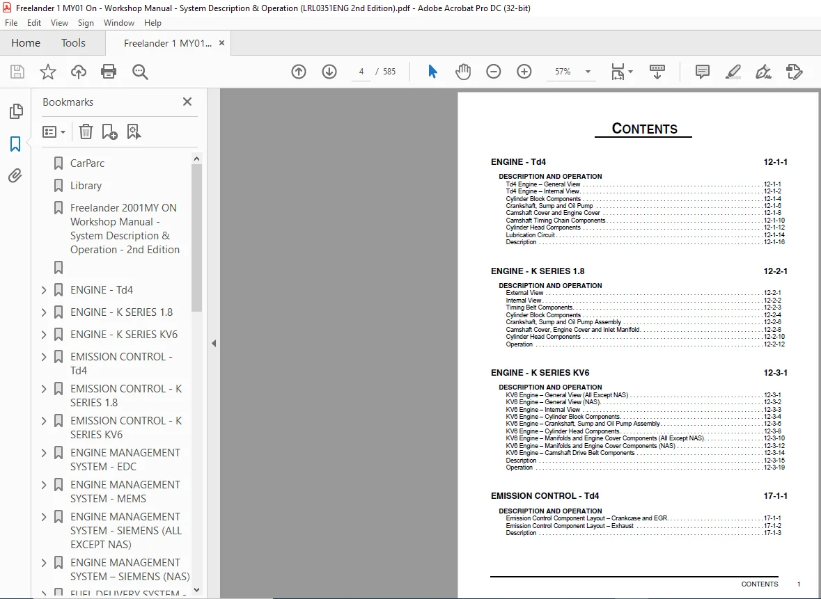
ENGINE – Td4 12-1-1
DESCRIPTION AND OPERATION
Td4 Engine – General View 12-1-1
Td4 Engine – Internal View 12-1-2
Cylinder Block Components 12-1-4
Crankshaft, Sump and Oil Pump 12-1-6
Camshaft Cover and Engine Cover 12-1-8
Camshaft Timing Chain Components 12-1-10
Cylinder Head Components 12-1-12
Lubrication Circuit 12-1-14
Description 12-1-16
ENGINE – K SERIES 1 8 12-2-1
DESCRIPTION AND OPERATION
External View 12-2-1
Internal View 12-2-2
Timing Belt Components 12-2-3
Cylinder Block Components 12-2-4
Crankshaft, Sump and Oil Pump Assembly 12-2-6
Camshaft Cover, Engine Cover and Inlet Manifold 12-2-8
Cylinder Head Components 12-2-10
Operation 12-2-12
ENGINE – K SERIES KV6 12-3-1
DESCRIPTION AND OPERATION
KV6 Engine – General View (All Except NAS) 12-3-1
KV6 Engine – General View (NAS) 12-3-2
KV6 Engine – Internal View 12-3-3
KV6 Engine – Cylinder Block Components 12-3-4
KV6 Engine – Crankshaft, Sump and Oil Pump Assembly 12-3-6
KV6 Engine – Cylinder Head Components 12-3-8
KV6 Engine – Manifolds and Engine Cover Components (All Except NAS) 12-3-10
KV6 Engine – Manifolds and Engine Cover Components (NAS) 12-3-12
KV6 Engine – Camshaft Drive Belt Components 12-3-14
Description 12-3-15
Operation 12-3-19
EMISSION CONTROL – Td4 17-1-1
DESCRIPTION AND OPERATION
Emission Control Component Layout – Crankcase and EGR 17-1-1
Emission Control Component Layout – Exhaust 17-1-2
Description 17-1-3
CONTENTS
2 CONTENTS
EMISSION CONTROL – K SERIES 1 8 17-2-1
DESCRIPTION AND OPERATION
Emission Control Component Layout – Crankcase and Exhaust 17-2-1
Emission Control Component Layout – EVAP 17-2-2
Description 17-2-3
EMISSION CONTROL – K SERIES KV6 17-3-1
DESCRIPTION AND OPERATION
Emission Control Component Layout – Crankcase and Exhaust (All Except NAS) 17-3-1
Emission Control Component Layout – Crankcase and Exhaust (NAS) 17-3-2
Emission Control Component Layout – EVAP (All Except NAS) 17-3-3
Emission Control Component Layout – EVAP (NAS) 17-3-4
Description 17-3-6
ENGINE MANAGEMENT SYSTEM – EDC 18-1-1
DESCRIPTION AND OPERATION
Engine Management Component Layout 18-1-2
Engine Management Control Diagram 18-1-4
Description 18-1-6
Operation 18-1-24
DESCRIPTION AND OPERATION
Cruise Control Component Layout 18-1-29
Cruise Control, Control Diagram 18-1-30
Description 18-1-32
Operation 18-1-34
ENGINE MANAGEMENT SYSTEM – MEMS 18-2-1
DESCRIPTION AND OPERATION
Engine Management Component Layout 18-2-2
MEMS3 Control Diagram 18-2-4
Description 18-2-6
Operation 18-2-29
ENGINE MANAGEMENT SYSTEM – SIEMENS (ALL EXCEPT NAS) 18-3-1
DESCRIPTION AND OPERATION
Engine Management System Component Layout 18-3-2
Engine Management System Control Diagram – Sheet 1 of 2 18-3-4
Engine Management System Control Diagram – Sheet 2 of 2 18-3-6
Description 18-3-8
Operation 18-3-22
CONTENTS
CONTENTS 3
DESCRIPTION AND OPERATION
Cruise Control System Component Layout – Sheet 1 of 2 18-3-29
Cruise Control System Component Layout – Sheet 2 of 2 18-3-30
Cruise Control System Control Diagram 18-3-32
Description 18-3-34
Operation 18-3-40
ENGINE MANAGEMENT SYSTEM – SIEMENS (NAS) 18-4-1
DESCRIPTION AND OPERATION
Engine Management System Component Location 18-4-2
Engine Management System Control Diagram – Sheet 1 of 2 18-4-4
Engine Management System Control Diagram – Sheet 2 of 2 18-4-6
Description 18-4-8
Operation 18-4-29
DESCRIPTION AND OPERATION
Cruise Control Component Location 18-4-31
Cruise Control System Control Diagram 18-4-32
Cruise Control Description 18-4-34
Cruise Control Operation 18-4-36
FUEL DELIVERY SYSTEM – Td4 19-1-1
DESCRIPTION AND OPERATION
Fuel Delivery System Component Layout 19-1-1
Fuel Delivery System Schematic Diagram 19-1-2
Description 19-1-3
FUEL DELIVERY SYSTEM – K SERIES 1 8 19-2-1
DESCRIPTION AND OPERATION
Fuel Delivery System Component Layout 19-2-1
Fuel Delivery System Schematic Diagram 19-2-2
Description 19-2-3
Operation 19-2-5
FUEL DELIVERY SYSTEM – K SERIES KV6 19-3-1
DESCRIPTION AND OPERATION
Fuel Delivery System Component Layout (All Except NAS) 19-3-1
Fuel Delivery System Component Layout (NAS) 19-3-2
Fuel Delivery System Schematic (All Except NAS) 19-3-3
Fuel Delivery System Schematic (NAS) 19-3-4
Description 19-3-5
Operation 19-3-11
CONTENTS
4 CONTENTS
COOLING SYSTEM – Td4 26-1-1
DESCRIPTION AND OPERATION
Cooling System Component Layout – Manual Gearbox, Sheet 1 of 2 26-1-2
Cooling System Component Layout – Manual Gearbox, Sheet 2 of 2 26-1-4
Cooling System Component Layout – Automatic Gearbox, Sheet 1 of 2 26-1-6
Cooling System Component Layout – Automatic Gearbox, Sheet 2 of 2 26-1-8
Cooling System Coolant Flow – Manual Gearbox Without FBH 26-1-10
Cooling System Coolant Flow – Manual Gearbox With FBH 26-1-11
Cooling System Coolant Flow – Automatic Gearbox Without FBH 26-1-12
Cooling System Coolant Flow – Automatic Gearbox With FBH 26-1-13
Cooling System Coolant Flow – Automatic Gearbox With Air Blast Transmission Cooler 26-1-14
Description 26-1-15
Operation 26-1-17
COOLING SYSTEM – K SERIES 1 8 26-2-1
DESCRIPTION AND OPERATION
Cooling System Component Layout 26-2-1
Cooling System Operation 26-2-2
Description 26-2-3
Operation 26-2-5
COOLING SYSTEM – K SERIES KV6 26-3-1
DESCRIPTION AND OPERATION
Cooling System Component Layout – Sheet 1 of 2 (All Except NAS and Gulf States) 26-3-2
Cooling System Component Layout – Sheet 1 of 2 (NAS and Gulf States) 26-3-4
Cooling System Component Layout – Sheet 2 of 2 26-3-6
Cooling System Coolant Flow (All Except NAS and Gulf States) 26-3-7
Cooling System Coolant Flow (NAS and Gulf States) 26-3-8
Description 26-3-9
Operation 26-3-10
MANIFOLD AND EXHAUST SYSTEM – Td4 30-1-1
DESCRIPTION AND OPERATION
Exhaust Manifold Component Layout 30-1-1
Inlet Manifold Component Layout 30-1-2
Exhaust System Component Layout 30-1-3
Description 30-1-4
CONTENTS
CONTENTS 5
MANIFOLD AND EXHAUST SYSTEM – K SERIES 1 8 30-2-1
DESCRIPTION AND OPERATION
Exhaust Manifold 30-2-1
Inlet Manifold 30-2-2
Exhaust System 30-2-3
Description 30-2-4
MANIFOLD AND EXHAUST SYSTEM – K SERIES KV6 30-3-1
DESCRIPTION AND OPERATION
Exhaust Manifold Component Layout (All Except NAS) 30-3-1
Inlet Manifold Component Layout 30-3-2
Inlet Manifold Chamber Component Layout 30-3-3
Exhaust System Component Layout (All Except NAS) 30-3-4
Exhaust System Component Layout – Sheet 1 of 2 (NAS) 30-3-5
Exhaust System Component Layout – Sheet 2 of 2 (NAS) 30-3-6
Description 30-3-7
Operation 30-3-10
CLUTCH 33-1
DESCRIPTION AND OPERATION
Clutch Components – K1 8 Engines 33-1
Clutch Components – Td4 Engines 33-2
Description 33-3
Operation 33-8
MANUAL GEARBOX – GETRAG 37-2-1
DESCRIPTION AND OPERATION
Getrag 5 Speed Transmission 37-2-1
Description 37-2-2
INTERMEDIATE REDUCTION DRIVE 41-1
DESCRIPTION AND OPERATION
Intermediate Reduction Drive 41-1
Description 41-2
Operation 41-3
CONTENTS
6 CONTENTS
AUTOMATIC GEARBOX – JATCO 44-1
DESCRIPTION AND OPERATION
JATCO Automatic Gearbox Component Location 44-1
JATCO Automatic Gearbox 44-2
JATCO Automatic Gearbox – Exploded View 44-3
JATCO Automatic Gearbox – Valve Block and Solenoid Valves 44-4
JATCO Automatic Gearbox Control Diagram 44-6
Description 44-8
Operation 44-40
DRIVESHAFTS 47-1
DESCRIPTION AND OPERATION
Drive Shaft and Propeller Shaft Component Layout 47-1
Front Drive Shaft Components 47-2
Rear Drive Shaft Components 47-3
Propeller Shaft and VCU Components 47-4
Description 47-5
REAR AXLE AND FINAL DRIVE 51-1
DESCRIPTION AND OPERATION
Rear Differential 51-2
Description 51-4
STEERING 57-1
DESCRIPTION AND OPERATION
Steering Components – Td4 57-1
Steering Components – K1 8 57-2
Steering Components – KV6 57-3
Description 57-4
Operation 57-13
FRONT SUSPENSION 60-1
DESCRIPTION AND OPERATION
Front Suspension Component Location 60-1
Front Suspension Component Detail 60-2
Description 60-4
CONTENTS
CONTENTS 7
REAR SUSPENSION 64-1
DESCRIPTION AND OPERATION
Rear Suspension Component Location 64-1
Rear Suspension Component Detail 64-2
Description 64-4
BRAKES 70-1
DESCRIPTION AND OPERATION
Brake System Layout (K1 8 and Td4) 70-1
Brake System Layout (KV6) 70-2
Description 70-3
Operation 70-15
DESCRIPTION AND OPERATION
Handbrake Component Layout 70-23
Description 70-24
RESTRAINT SYSTEMS 75-1
DESCRIPTION AND OPERATION
SRS Component Layout 75-1
SRS Control Diagram 75-2
Description 75-3
Operation 75-10
DESCRIPTION AND OPERATION
Front Seat Belt Components 75-11
Rear Seat Belt Components – Three Door Models 75-12
Rear Seat Belt Components – Five Door Models 75-13
Description 75-14
HEATING AND VENTILATION 80-1
DESCRIPTION AND OPERATION
Heating and Ventilation System Component Layout 80-1
Heater Assembly Components 80-2
Fuel Burning Heater Component Layout 80-3
PTC Heater System Component Layout 80-4
Description 80-5
Operation 80-18
CONTENTS
8 CONTENTS
AIR CONDITIONING 82-1
DESCRIPTION AND OPERATION
A/C Refrigerant System Component Layout – KV6 Series Engines 82-1
A/C Refrigerant System Component Layout – K1 8 Series Engines 82-2
A/C Refrigerant System Component Layout – Td4 Series Engines 82-3
A/C System Schematic Layout 82-4
A/C Control Component Layout 82-5
A/C System Control Schematic – K1 8 and Non NAS KV6 82-6
A/C System Control Schematic – Td4 and NAS KV6 82-8
Description 82-10
Operation 82-23
WIPERS AND WASHERS 84-1
DESCRIPTION AND OPERATION
Windscreen Wiper Components 84-1
Rear Screen Wiper Components 84-2
Washer Components 84-3
Description 84-4
Operation 84-7
CONTROL UNITS 86-3-1
DESCRIPTION AND OPERATION
Control Unit Locations 86-3-1
Description 86-3-2
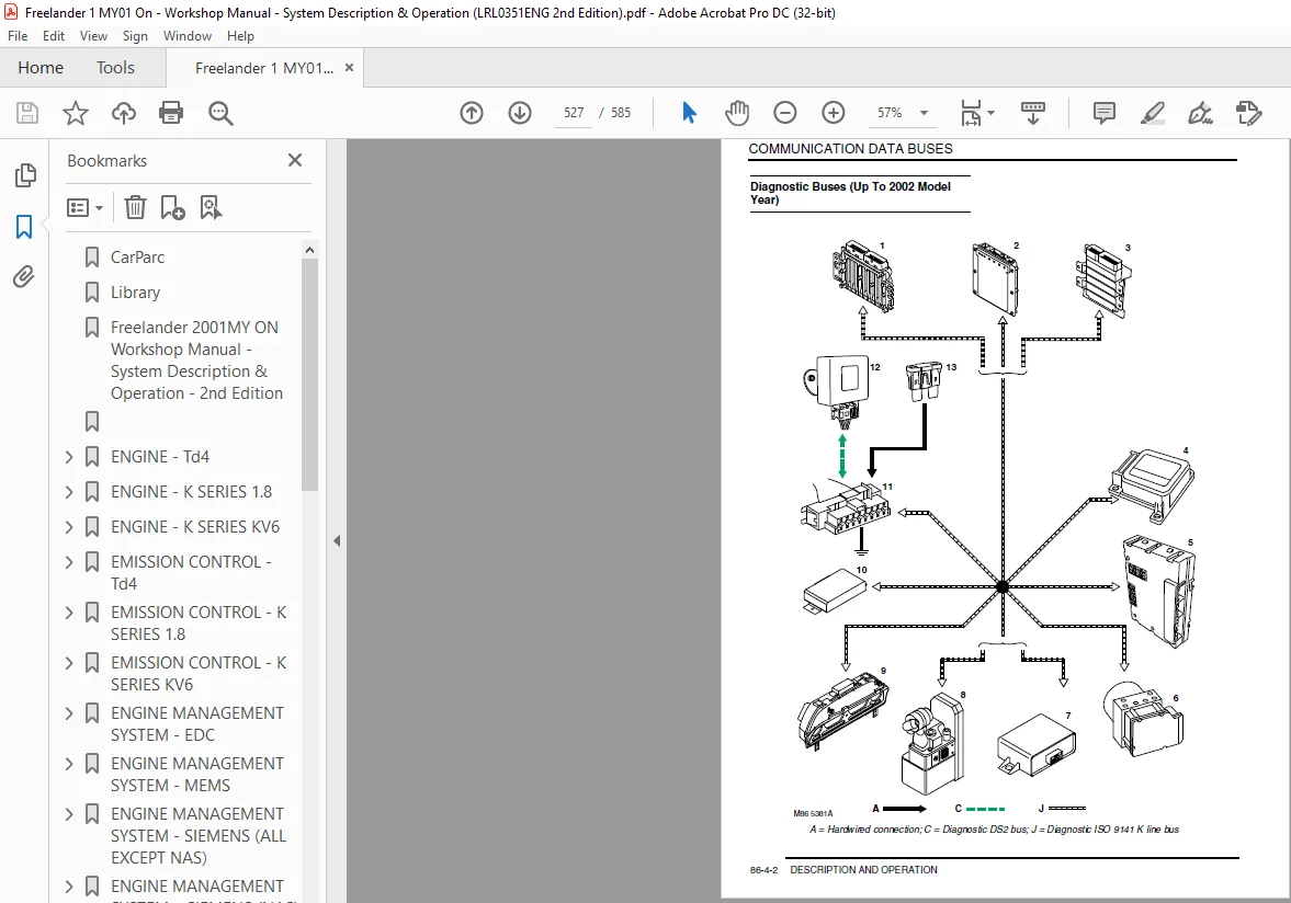
COMMUNICATION DATA BUSES 86-4-1
DESCRIPTION AND OPERATION
CAN Bus Control Diagram 86-4-1
Diagnostic Buses (Up To 2002 Model Year) 86-4-2
Diagnostic Buses (From 2002 Model Year) 86-4-4
Description 86-4-6
SECURITY 86-5-1
DESCRIPTION AND OPERATION
Locking and Alarm System Component Layout 86-5-1
Immobilisation System Component Layout 86-5-2
Immobilisation System Control Diagram 86-5-3
Locking and Alarm System Control Diagram 86-5-4
Description 86-5-6
Operation 86-5-15
CONTENTS
CONTENTS 9
WINDOWS 86-6-1
DESCRIPTION AND OPERATION
Window Component Layout 86-6-2
Side Door Window Control Diagram 86-6-4
Tail Door Window Control Diagram 86-6-6
Description 86-6-7
Operation 86-6-10
NAVIGATION SYSTEM 86-7-1
DESCRIPTION AND OPERATION
Navigation System Component Location 86-7-1
Description 86-7-2
INSTRUMENTS 88-1
DESCRIPTION AND OPERATION
Instrument Pack Component Location – Front View (All Markets, Except NAS) 88-1
Instrument Pack Component Location – Front View (NAS Only) 88-2
Instrument Pack Component Layout – Rear View 88-3
Instrument Pack Components – Exploded View 88-4
Description 88-5
LAND ROVER FREELANDER 2001MY ON WORKSHOP MANUAL – SYSTEM DESCRIPTION & OPERATION – 2ND EDITION:
IMAGES PREVIEW OF THE MANUAL:


PLEASE NOTE:
- This is not a physical manual but a digital manual – meaning no physical copy will be couriered to you. The manual can be yours in the next 2 mins as once you make the payment, you will be directed to the download page IMMEDIATELY.
- This is the same manual used by the dealers inorder to diagnose your vehicle of its faults.
- Require some other service manual or have any queries: please WRITE to us at [email protected]
S.V