Landoll Bendi Forklift B330 AC Electric Narrow Aisle Forklift Parts Manual
$24.95
Landoll Bendi Forklift B330 AC Electric Narrow Aisle Forklift Parts Manual F-549-0211 – PDF DOWNLOAD
Description
Landoll Bendi Forklift B330 AC Electric Narrow Aisle Forklift Parts Manual F-549-0211 – PDF DOWNLOAD
FILE DETAILS:
Landoll Bendi Forklift B330 AC Electric Narrow Aisle Forklift Parts Manual F-549-0211 – PDF DOWNLOAD
Language : English
Pages :115
Downloadable : Yes
File Type : PDF
TABLE OF CONTENTS:
Landoll Bendi Forklift B330 AC Electric Narrow Aisle Forklift Parts Manual F-549-0211 – PDF DOWNLOAD
Instructions for Ordering Parts 5
Figure 1-1: Identification Plate 5
Illustrated Parts List 7
Figure 2-1: General Assembly 7
GENERAL ASSEMBLY 7
Figure 2-2: Counterweight and Cover Assembly (1 of 3) 8
Figure 2-3: Counterweight and Cover Assembly (2 of 3) 9
Figure 2-4: Counterweight and Cover Assembly (3 of 3) 10
COUNTERWEIGHT AND COVER ASSEMBLY (0010) 11
Figure 2-5: Compartment Assembly 12
COMPARTMENT ASSEMBLY (0040) 13
Figure 2-6: Hydraulic Tank Installation 14
HYDRAULIC TANK INSTALLATION (0041 & 0050) 15
Figure 2-7: Hydraulic Tank Assembly 16
HYDRAULIC TANK ASSEMBLY (0041) 17
Figure 2-8: Pump Installation 18
PUMP INSTALLATION (0042) 18
Figure 2-9: Hydraulic Diagram 19
HYDRAULIC DIAGRAM 20
Figure 2-10: Rear Spindle and Brake Installation 22
REAR SPINDLE AND BRAKE INSTALLATION 22
Figure 2-11: Pump Assembly 23
PUMP ASSEMBLY 24
Figure 2-12: Brake Assembly 25
BRAKE ASSEMBLY 26
Figure 2-13: Rear Tire Assembly 27
REAR TIRE ASSEMBLY 27
Figure 2-14: Brake Pedal Installation 28
BRAKE PEDAL INSTALLATION 28
Figure 2-15: Brake Assembly 29
BRAKE PEDAL ASSEMBLY 30
Figure 2-16: Hydraulic Valve Installation 31
HYDRAULIC VALVE INSTALLATION 32
Figure 2-17: Park Brake Installation 33
PARK BRAKE INSTALLATION 34
Figure 2-18: Control Valve Handle Assembly – Before 12/15/2010 35
CONTROL VALVE HANDLE ASSEMBLY 36
Figure 2-19: Control Valve Handle Assembly – After 12/15/2010 37
CONTROL VALVE HANDLE ASSEMBLY 38
Figure 2-20: Steering Column and Tubing Installation 39
STEERING COLUMN AND TUBING INSTALLATION 40
Figure 2-21: Steering Column Assembly 41
STEERING COLUMN ASSEMBLY 42
Figure 2-22: Steering Column Parts 43
STEERING COLUMN PARTS 44
Figure 2-23: Stop Button Installation 45
STOP BUTTON INSTALLATION 45
Figure 2-24: Pump Controller Installation 46
PUMP CONTROLLER INSTALLATION 46
Figure 2-25: Contactor Installation 47
CONTACTOR INSTALLATION 47
Figure 2-26: Rear Wheel/Tire Assembly 48
REAR WHEEL/TIRE ASSEMBLY 48
Figure 2-27: Drive Control and Electrical Installation 49
DRIVE CONTROL AND ELECTRICAL INSTALLATION 50
Figure 2-28: Steer Motor Installation 51
STEER MOTOR INSTALLATION 52
Figure 2-29: Steering Motor Assembly 53
STEERING MOTOR ASSEMBLY 54
Figure 2-30: Front End and Drive Mount Installation 55
FRONT END AND DRIVE MOUNT INSTALLATION 56
Figure 2-31: Steer Gear Installation 57
STEER GEAR INSTALLATION 58
Figure 2-32: Drive and Motor Cover Installation 59
DRIVE AND MOTOR COVER INSTALLATION 60
Figure 2-33: 29:1 Gearbox 61
GEARBOX, BREVINI 29:1 INLINE 62
Figure 2-34: Drive Wheel Assembly 63
DRIVE WHEEL ASSEMBLY 63
Figure 2-35: Overhead Guard Mount Installation 64
OVERHEAD GUARD MOUNT INSTALLATION 64
Figure 2-36: Seatbase Installation 65
SEATBASE INSTALLATION 66
Figure 2-37: Seat Assembly 67
SEAT ASSEMBLY 68
Figure 2-38: Overhead Guard Mount Assembly 69
OVERHEAD GUARD ASSEMBLY 70
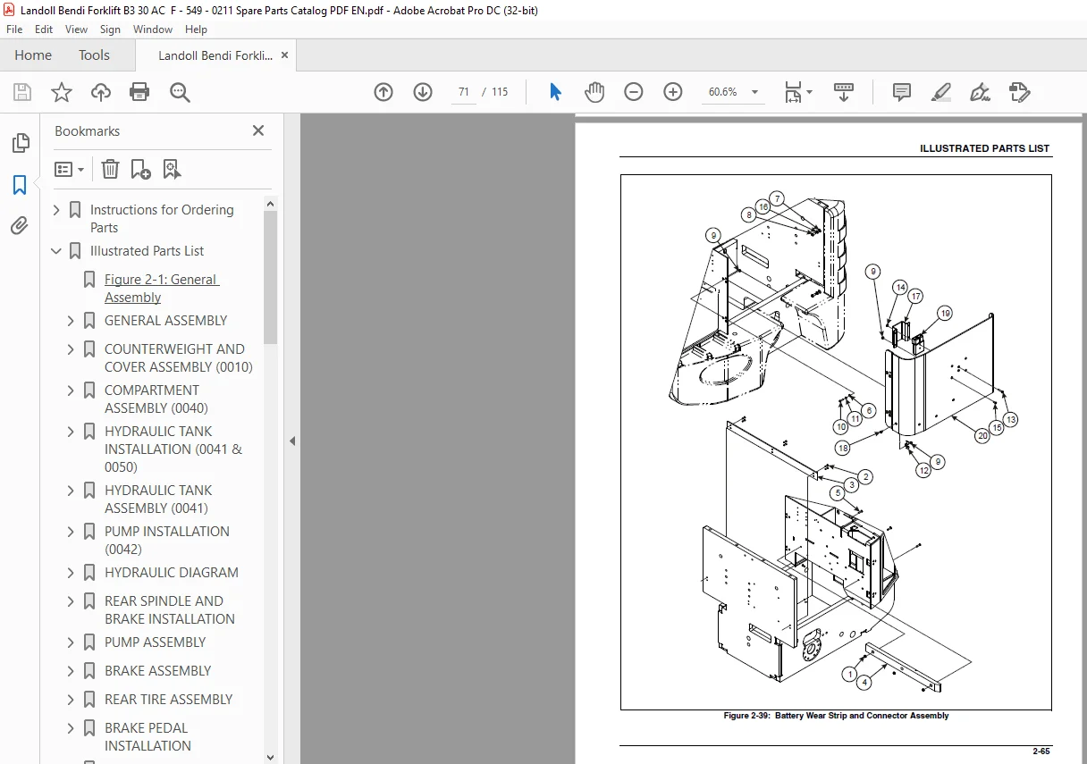
Figure 2-39: Battery Wear Strip and Connector Assembly 71
BATTERY WEAR STRIP AND CONNECTOR ASSEMBLY 72
Figure 2-40: Tilt Cylinder Installation 73
TILT CYLINDER INSTALLATION 74
Figure 2-41: Tilt Cylinder 75
TILT CYLINDER 75
Figure 2-42: Steering Control Valve 76
STEERING CONTROL VALVE 76
Figure 2-43: Hydraulic Control Valve 77
HYDRAULIC CONTROL VALVE 77
Figure 2-44: Lift Pump Motor Assembly 78
LIFT PUMP MOTOR ASSEMBLY 78
Figure 2-45: Floor Plate Installation 79
FLOOR PLATE AND ACCELERATOR INSTALLATION 80
Figure 2-46: Battery Door Assembly 81
BATTERY DOOR ASSEMBLY 82
Figure 2-47: Stop and Tow Pin Installation 83
STOP AND TOW PIN INSTALLATION 84
Figure 2-48: Rollout Battery Tray Assembly (Optional) 85
ROLLOUT BATTERY TRAY ASSEMBLY (OPTION) 86
Figure 2-49: Overhead Guard, Alarm, and Lighting Assembly (1 of 2) 87
Figure 2-50: Overhead Guard, Alarm, and Lighting Assembly (2 of 2) 88
ALARM AND LIGHTING ASSEMBLY 89
Figure 2-51: Steering Column and Seat Base Harness Installation 91
Figure 2-52: Optional Lighting Harness Installation 92
Figure 2-53: Harness Installation 93
Figure 2-54: Harness Installation 94
LIGHT WIRING INSTALLATION 95
Figure 2-55: Heavy Cable Installation 96
HEAVY CABLE INSTALLATION 97
Figure 2-56: Forks 98
FORKS 98
Figure 2-57: Load Backrest Options 99
LOAD BACKREST OPTIONS 99
Figure 2-58: Mast Options100
MAST OPTIONS100
Figure 2-59: Decals101
Figure 2-60: Decal Placement102
DECAL PLACEMENT103
ACCESSORIES104
Numerical Landoll Part Number Index106
IMAGES PREVIEW OF THE MANUAL:
S.M 5/24