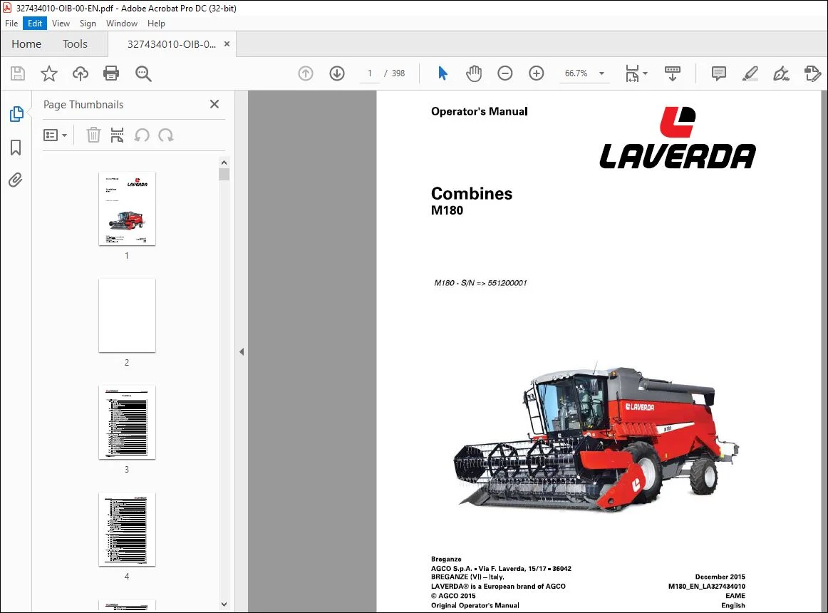
Laverda EU Harvesting M180 Combines Operator’s Manual LA327434010 – PDF DOWNLOAD
Original price was: $86.95.$28.95Current price is: $28.95.
Laverda EU Harvesting M180 Combines Operator’s Manual LA327434010 – PDF DOWNLOAD
Description
Laverda EU Harvesting M180 Combines Operator’s Manual LA327434010 – PDF DOWNLOAD
FILE DETAILS:
Laverda EU Harvesting M180 Combines Operator’s Manual LA327434010 – PDF DOWNLOAD
Language : English
Pages : 398
Downloadable : Yes
File Type : PDF
Size: 64.9 MB
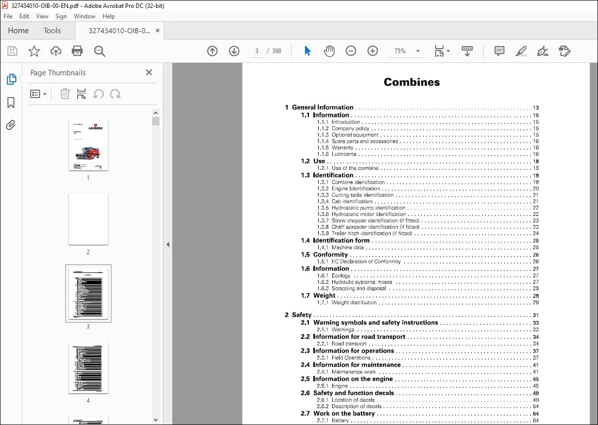
TABLE OF CONTENTS:
Laverda EU Harvesting M180 Combines Operator’s Manual LA327434010 – PDF DOWNLOAD
1 General Information 13
1 1 Information 15
1 1 1 Introduction 15
1 1 2 Company policy 15
1 1 3 Optional equipment 15
1 1 4 Spare parts and accessories 16
1 1 5 Warranty 16
1 1 6 Lubricants 16
1 2 Use 18
1 2 1 Use of the combine 18
1 3 Identification 19
1 3 1 Combine identification 19
1 3 2 Engine Identification 20
1 3 3 Cutting table identification 21
1 3 4 Cab identification 21
1 3 5 Hydrostatic pump identification 22
1 3 6 Hydrostatic motor identification 22
1 3 7 Straw chopper identification (if fitted) 23
1 3 8 Chaff spreader identification (if fitted) 23
1 3 9 Trailer hitch identification (if fitted) 24
1 4 Identification form 25
1 4 1 Machine data 25
1 5 Conformity 26
1 5 1 EC Declaration of Conformity 26
1 6 Information 27
1 6 1 Ecology 27
1 6 2 Hydraulic systems: hoses 27
1 6 3 Scrapping and disposal 28
1 7 Weight 29
1 7 1 Weight distribution 29
2 Safety 31
2 1 Warning symbols and safety instructions 33
2 1 1 Warnings 33
2 2 Information for road transport 34
2 2 1 Road transport 34
2 3 Information for operations 37
2 3 1 Field Operations 37
2 4 Information for maintenance 41
2 4 1 Maintenance work 41
2 5 Information on the engine 45
2 5 1 Engine 45
2 6 Safety and function decals 49
2 6 1 Location of decals 49
2 6 2 Description of decals 54
2 7 Work on the battery 64
2 7 1 Battery 64
2 8 Safety devices 65
2 8 1 Emergency exit 65
Combines
M180_EN_LA327434010
Table of contents C:LRVERDR
2 8 2 Operator presence device 66
2 8 3 Safety belts 67
2 8 4 Table safety stops 68
2 8 5 Safety guard for main crop elevator 69
2 8 6 Safety Stop 69
2 8 7 Sprags for wheels 70
2 8 8 Audible alarm for reversing 71
2 8 9 Reflectors for road transport 72
2 8 10 Safety Guards 73
2 8 11 Fall protection rails 73
2 8 12 Safety devices for operations to be carried out in the upper part of the machine 74
2 8 13 Straw chopper 75
2 8 14 Fire extinguisher 75
2 9 Trailer hitch 76
2 9 1 Automatic towing hooks 76
2 9 2 CUNA and CE trailer hitches 77
2 9 2 1 Procedure for attaching and removing 78
2 9 2 2 Drawbar coupling 79
2 9 3 Fixed trailer hitch (non-automatic – CUNA type) 79
2 10 Machine lifting 80
2 10 1 Attachment points 80
2 11 Towing 81
2 11 1 Towing the combine 81
2 12 Further information 82
2 12 1 Noise level in the cab 82
2 12 2 Vibrations in the cab 82
2 12 3 Statutory regulations 82
2 12 4 Electromagnetic emissions 83
2 13 Notes 84
2 13 1 Notes for road transport 84
3 Operation 87
3 1 Combine operation 89
3 1 1 Crop processing 89
3 2 Stage 1 90
3 2 1 Feeding 90
3 3 Stage 2 91
3 3 1 Threshing 91
3 4 Stage 3 92
3 4 1 Separation 92
3 5 Stage 4 93
3 5 1 Cleaning 93
3 6 Stage 5 94
3 6 1 Grain storage and unloading 94
4 Controls and Instruments 95
4 1 Steering column 97
4 1 1 Components and adjustments 97
4 2 Multifunction lever 98
4 2 1 Main components 98
4 3 Instrument panel 99
4 3 1 Front control panel 99
4 3 2 Rear control panel 101
4 3 3 Multiple light indicators 105
4 3 4 On-board Computer 106
Combines
M180_EN_LA327434010
C:LRVERDR Table of contents
4 3 4 1 Graphical user interface 108
4 3 4 2 Day/night mode 110
4 3 4 3 Operational parameters 111
4 3 4 4 Auto-calibration 111
4 3 4 5 Hectare counter 112
4 3 4 6 No communication 112
4 3 4 7 Alarm statuses 113
4 3 5 Performance monitor (on request) 113
4 3 5 1 Using the monitor 114
4 3 5 2 Selecting the measurement range (straw walker, sieves or total) 114
4 3 5 3 Calibrating the bar cursor scale 115
4 3 5 4 Sensitivity adjustment 115
4 3 5 5 Shifting to forward speed monitoring 116
4 3 5 6 Summary of keyboard functions 116
4 4 Controls at the operator seat 117
4 4 1 Description 117
4 5 Cab 119
4 5 1 Cab controls (top right-hand side) 119
4 5 2 Operator seat 122
4 5 3 Preparation for radio installation 123
4 5 4 Reading light 123
4 5 5 Document Pocket 124
4 5 6 Air conditioning in the cab 125
4 5 6 1 Pressurization 126
4 5 7 Heating 127
4 6 Access to combine components 128
4 6 1 Access to the operator platform 128
4 6 2 Accessing and cleaning the front windscreen of the cab 129
4 6 3 Access to the engine compartment 130
4 6 4 Access to the grain tank 131
4 6 5 Access to the inside of the grain tank 132
4 7 Engine 133
4 7 1 Starting the engine 133
4 7 2 Useful advice 134
4 7 3 Stopping the engine 135
4 8 Road transport 136
4 8 1 Operations to be carried out before transportation 136
4 8 2 Position light and sidelight adjustment 137
4 9 Using the combine 138
4 9 1 Operations to be carried out before use 138
5 Field Operations 139
5 1 General Information 141
5 1 1 Notes 141
5 1 2 Before operating the machine in the field 141
5 2 Starting and Stopping the Combine 143
5 2 1 Procedure to follow 143
5 3 Cutting table 145
5 3 1 Attaching the cutting table 145
5 3 1 1 Adjustments for attaching the cutting table 147
5 3 2 Removing the table 148
5 3 3 Adjustment of cutting table ground clearance 149
5 4 Main Crop Elevator 150
5 4 1 Adjustments 150
5 4 1 1 Access to the main components 152
5 4 2 Reverse drive system 153
Combines
M180_EN_LA327434010
Table of contents C:LRVERDR
5 5 Cylinder Housing 154
5 5 1 Components 154
5 5 2 Threshing drum 155
5 5 3 Concave 156
5 5 3 1 Concave filler plates 157
5 5 3 2 Parallelism between the threshing drum and concave 158
5 5 3 3 Unblocking the threshing drum 159
5 5 3 4 Universal wheat/maize concave 160
5 5 3 5 Basic concave settings 161
5 5 3 6 Spike-toothed Cylinder/Concave (for rice) 161
5 5 4 Rear beater 163
5 6 Straw walkers 164
5 6 1 Description and adjustments 164
5 7 Main Grain Pan 165
5 7 1 Description 165
5 7 2 Checking the main grain pan 166
5 7 3 Cleaning the main grain pan 167
5 7 4 Stone trap assembly removal/refitting 168
5 8 Fanning Mill 170
5 8 1 Description and adjustments 170
5 8 1 1 Fanning mill for threshing light seed crops 172
5 9 Top sieve 173
5 9 1 Adjustment 173
5 10 Bottom sieve 177
5 10 1 Adjustment 177
5 11 Returns 179
5 11 1 Description and adjustments 179
5 12 Grain tank 181
5 12 1 Description 181
5 12 1 1 Grain tank unloading auger 182
5 12 1 2 Sensor to measure tank filling 183
5 12 1 3 Grain tank control window 183
5 12 1 4 Doors for Grain Tank Maintenance and Cleaning 184
5 12 1 5 Vertical auger tank drain door 185
5 12 1 6 Tankbottomdoor 186
5 12 1 7 Grain Tank Cover 187
5 12 1 8 Basic Settings 188
6 Lubrication and Maintenance 191
6 1 General Information 193
6 1 1 Lubrication and Maintenance 193
6 2 Preliminary Service Inspection 194
6 2 1 After the first 50 working hours 194
6 3 Scheduled Service Inspection 195
6 3 1 When and where to carry it out 195
6 3 2 Interval – 10 hours 197
6 3 2 1 Cylinder variator (1) 197
6 3 2 2 Engine oil (2) 198
6 3 2 3 Coolant expansion tank (3) 199
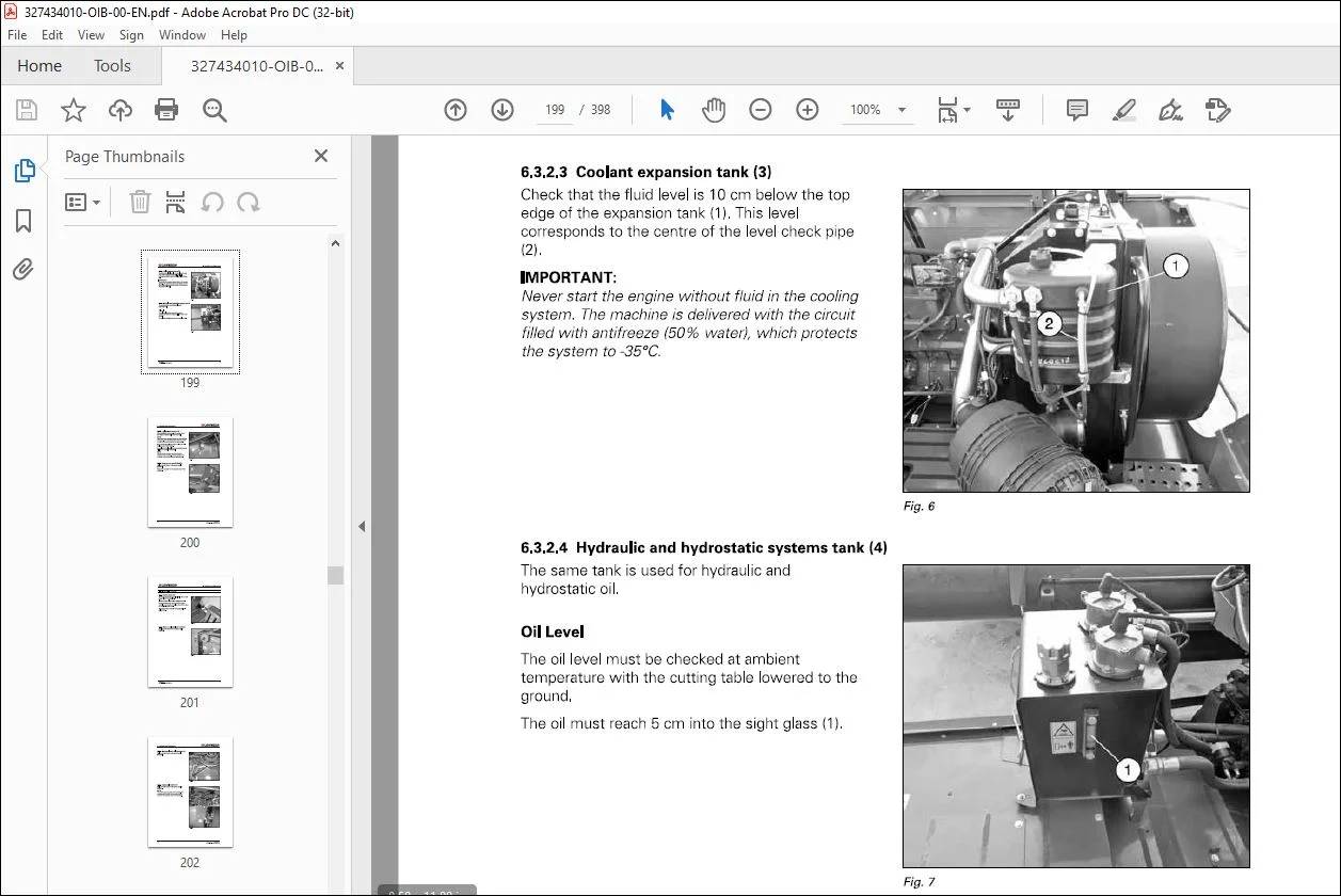
6 3 2 4 Hydraulic and hydrostatic systems tank (4) 199
6 3 2 5 Prefilter/water separator (5) 200
6 3 2 6 Straw chopper rotor (if fitted) (6) 200
6 3 3 Interval – 75 hours 201
6 3 3 1 Service brakes (11) 201
6 3 3 2 Main crop elevator lower shaft (12) 201
6 3 3 3 Main crop elevator belt tensioner (13) 202
Combines
M180_EN_LA327434010
C:LRVERDR Table of contents
6 3 3 4 Fanning mill variator (14) 202
6 3 3 5 Crop-unloading auger drive belt tensioner (15) 203
6 3 3 6 Coupling bushes of final drive shafts (16) 203
6 3 3 7 Rear axle support (17) 204
6 3 3 8 Rear axle king pins (18) 204
6 3 3 9 Rear straw-walker shaft supports (19) 205
6 3 3 10 Unloading auger bottom gearbox (20) 205
6 3 3 11 Unloading auger top gearbox (21) 206
6 3 3 12 Table drive-belt tensioner (22) 206
6 3 3 13 Track frames (23) 207
6 3 3 14 Cab air filters (24) 207
6 3 3 15 Evaporator (25) 208
6 3 3 16 Condenser (26) 209
6 3 3 17 Radiators and hydraulic oil (27) 210
6 3 3 18 Adjusting the rotary screen brushes and aspirator brushes 211
6 3 3 19 Chaff spreader drive (if fitted) (28) 212
6 3 4 Interval – 150 hours 213
6 3 4 1 Park brake (41) 213
6 3 4 2 Gearbox (42) 213
6 3 4 3 Final drives (43) 214
6 3 4 4 Unloading auger bottom gearbox (44) 214
6 3 4 5 Main crop elevator supports (45) 215
6 3 4 6 Reversing-belt tensioner-arm pin (46) 215
6 3 4 7 Main clutch (47) 216
6 3 4 8 Tailings-auger left support (48) 216
6 3 4 9 Windscreen wash fluid reservoir (49) 217
6 3 4 10 Threshing-mechanism belt tensioner (50) 217
6 3 4 11 Hydrostatic pump belt tensioner (51) 218
6 3 4 12 Unloading auger slewing ring (52) 218
6 3 4 13 Engine air filter (53) 219
6 3 4 14 Straw-chopper driven belt tensioner (54) 220
6 3 4 15 Straw chopper drive-belt tensioner (55) 220
6 3 4 16 Engine (56) 220
6 3 4 17 Straw chopper layshaft (57) 222
6 3 4 18 Return rotary-screen belt tensioner (58) 222
6 3 4 19 Rotary-screen belt tensioner (59) 223
6 3 4 20 Radiator-fan drive belt tensioner (60) 223
6 3 5 Interval – 225 hours 223
6 3 5 1 Engine oil and filters (71) 223
6 3 6 Interval – 450 hours 227
6 3 6 1 Battery (81) 227
6 3 6 2 Dehydrator filter (82) 228
6 3 6 3 Final drives (83) 229
6 3 6 4 Gearbox (84) 229
6 3 6 5 Hydraulic oil intake filter (85) 230
6 3 6 6 Hydrostatic transmission filter (86) 231
6 3 6 7 Hydraulic systems oil (87) 232
6 3 6 8 Hydraulic and hydrostatic system return filter (88) 233
6 3 6 9 Engine diesel-fuel filters (89) 234
6 3 6 10 Catalytic fluid filter (90) 235
6 4 Periodical maintenance operations 236
6 4 1 Description 236
6 4 1 1 Engine valves (1) 237
6 4 1 2 Coolant (2) 238
6 4 1 3 Service brake circuit fluid (3) 239
6 4 1 4 Diesel fuel tank (4) 239
6 4 1 5 Turbocharger (5) 240
6 4 1 6 Hydraulic hoses (6) 240
Combines
M180_EN_LA327434010
Table of contents C:LRVERDR
6 5 Lubrication 241
6 5 1 Summary table 241
7 Adjustments 243
7 1 Adjustments 245
7 1 1 Important information 245
7 2 Belt and chain adjustment 246
7 2 1 Belts and chains (left-hand side) 246
7 2 1 1 Feeder drive belt (1) 246
7 2 1 2 Threshing unit drive belt (2) 247
7 2 1 3 Unloading auger drive belt (3) 247
7 2 1 4 Hydrostatic pump drive belt (4) 248
7 2 1 5 Chaff spreader drive belt (if fitted) (5) 249
7 2 1 6 Reversing drive belt (6) 249
7 2 1 7 Main transmission belt (7) 250
7 2 1 8 Clean grain and tailings augers drive belt (8) 250
7 2 1 9 Straw walker drive belt (9) 251
7 2 1 10 Cutting table drive belt (10) 251
7 2 1 11 Unloading auger chain (11) 252
7 2 1 12 Straw chopper drive belt (if fitted) (12) 252
7 2 1 13 Straw chopper drive belt (if fitted) (13) 253
7 2 2 Belts and chains (right-hand side) 253
7 2 2 1 Belt drive for rotary screen (21) 254
7 2 2 2 Counter drive for rotary screen (22) 254
7 2 2 3 Drive belt for alternator and engine coolant pump (23) 255
7 2 2 4 Radiator fan drive belt (24) 255
7 2 2 5 Belt drive for cylinder variator (25) 256
7 2 2 6 Belt drive for fanning mill variator (26) 257
7 2 2 7 Top chain drive for tailings auger (27) 258
7 2 2 8 Tailings elevator chain (28) 258
7 2 2 9 Tank filling auger drive chain (29) 259
7 2 2 10 Crop elevator chain (30) 259
7 2 2 11 Front crop-elevator chain (31) 260
7 2 2 12 Cab air-conditioning compressor drive belt (32) 260
7 2 2 13 Dust aspirator drive belt (33) 261
7 3 Slip clutches 262
7 3 1 Description 262
7 3 1 1 Clutch for main crop elevator upper shaft (1) 262
7 3 1 2 Clutch for shaker shoe counter drive (2) 262
7 3 1 3 Shear bolt for unloading auger counter drive (3) 263
7 4 Tires 264
7 4 1 Tire pressure 264
7 4 2 Replacement of Front Wheels 264
7 4 3 Replacement of Rear Wheels 265
7 4 4 Front wheel assembly 267
7 4 5 Rear wheel assembly 268
7 5 Brakes 269
7 5 1 Service brakes 269
7 5 2 Park brake 270
7 6 Rear axle 271
7 6 1 Toe-in setting 271
7 6 2 Steering ram ball joints 271
7 6 3 Rear axle support 272
7 7 Battery 273
7 7 1 Battery Replacement 273
7 7 2 Suggestions regarding the battery 273
Combines
M180_EN_LA327434010
C:LRVERDR Table of contents
7 7 3 Indicator Light for Battery Charging 274
8 Systems 275
8 1 Safety Precautions 277
8 1 1 Notes 277
8 2 Engine supply system 278
8 2 1 Permitted fuels 278
8 2 2 Fuel Circuit 278
8 2 3 Bleeding the Fuel Supply Circuit 280
8 2 4 Catalytic fluid tank (DEF) 281
8 2 5 Injection system operation 282
8 3 Engine air intake and exhaust system 283
8 3 1 Operation 283
8 4 Engine cooling system 285
8 4 1 Coolant 285
8 4 2 Engine cooling system operation 286
8 5 Engine lubrication system 287
8 5 1 Operation 287
8 5 2 Oil vapor recovery system 288
8 6 SCR system 289
8 6 1 Operation 289
8 7 Hydraulics system 291
8 7 1 Pumps and fuel tank 291
8 7 2 Table positioning hydraulic circuits 292
8 7 2 1 Cutting table oleopneumatic shock absorber 293
8 7 2 2 Hose burst valve 293
8 7 2 3 Cutting table positioning pressure switch 294
8 7 3 Hydraulic steering system 295
8 7 4 Auxiliary hydraulics circuit 296
8 8 Hydrostatic transmission system 297
8 8 1 Front-wheel drive 297
8 9 Electrical system 298
8 9 1 Main components 298
8 9 2 Fuses 299
8 9 3 Additional fuses 302
8 9 4 Cab fuses 305
8 9 5 Relays 306
8 9 5 1 Additional relays 308
8 9 5 2 Various relays 309
8 9 6 Control units 310
8 9 6 1 Engine sensors and control unit 311
8 9 7 Connections for additional equipment 312
8 9 7 1 Electric connectors 312
8 9 8 Headlight adjustment 314
8 9 9 Unloading area light 315
8 9 10 Reversing area light 315
8 9 11 Light in grain tank 316
8 9 12 Engine access-ladder light 316
9 Troubleshooting 317
9 1 Description 319
9 1 1 Feeding 319
9 1 2 Threshing 319
9 1 3 Separation and cleaning 321
9 1 4 Hydrostatic Transmission 324
9 1 5 Engine 325
Combines
M180_EN_LA327434010
Table of contents C:LRVERDR
9 1 6 Hydraulics system 327
9 1 7 Electrical system 328
9 1 8 Air conditioning circuit 329
9 1 9 Straw chopper 329
10 Off-Season Storage 333
10 1 Procedure to follow 335
10 1 1 Operations to be carried out after the harvest 335
10 1 2 Ordering spare parts 336
10 1 3 Operations to be carried out before the new season 336
11 Optional equipment 339
11 1 Information 341
11 1 1 General considerations 341
11 2 Optional equipment 342
11 2 1 Auxiliary table lifting ram 342
11 2 2 Camera 343
11 2 3 Additional rear view mirrors 343
11 2 4 Additional lights (for work) 344
11 2 5 Performance monitor 344
11 2 6 Windbreak 345
11 2 7 Additional fire extinguisher 345
11 2 8 Diesel fuel filter 346
11 2 9 Additional Portable Lamp 346
11 2 10 Weight and moisture control monitor 347
11 2 11 Trailer hitch 347
11 2 12 Refrigerator 348
11 2 13 Cylinder cover 348
11 2 14 Tailings cover plate 349
11 2 15 Top sieve 349
11 2 16 Bottom sieve 350
11 2 17 Electrically-operated sieves and returns sensors 351
11 2 18 Cutting height control 352
11 2 19 Hydraulic quick couplers 352
11 3 Equipment for threshing 353
11 3 1 Equipment for maize 353
11 3 2 Equipment for corn-cob 354
11 3 3 Equipment for rice 355
11 3 4 Equipment for light seed crops 355
11 3 5 Equipment for soya and peas 356
11 4 Ballast weights 357
11 4 1 Description 357
11 4 2 Ballast weights on rear axle 357
11 4 3 Ballast weights on the straw walker hood for machines without straw chopper 358
11 4 4 Ballast weights on the rear wheels with a liquid mix (for tubeless tires) 359
11 4 5 Filling tires with anti-freeze solutions 360
11 5 Straw chopper 361
11 5 1 Transport position 361
11 5 2 Working position 362
11 5 3 Operating the straw chopper 363
11 5 4 Disengaging the straw chopper 365
11 5 5 Access to the straw chopper rotor 365
11 5 6 Straw chopper rotor knives 365
11 5 7 Counter-knives 366
11 5 8 Chopping quality 366
11 5 9 Use of straw chopper in maize 368
11 6 Chaff Spreader 370
Combines
M180_EN_LA327434010
C:LRVERDR Table of contents
11 6 1 Working and maintenance positions 370
11 6 2 Chaff spreader speed 372
11 6 3 Disengaging the chaff spreader 372
11 6 4 Chaff spreader belt tensioning 372
11 7 Tracks 373
11 7 1 Use and maintenance 373
11 7 2 Track chain tension 374
12 Technical Specifications 375
12 1 Wheels and tires 377
12 1 1 information 377
12 1 2 Wheel tightening torque 377
12 1 3 Tire capacity 377
12 1 4 Tire equipment- front axle 378
12 1 5 Tire equipment – rear axle 379
12 1 6 Tire equipment – Version with half-tracks on front axle 380
12 2 Dimensions 381
12 2 1 Combine dimensions 381
12 2 2 Tracks with runners 383
12 2 3 Clearance between unloading auger and table 384
12 2 4 Available cutting tables and weights 384
12 2 5 Clearance between unloading auger and ground 385
12 3 Technical specifications 386
12 3 1 Feeding unit 386
12 3 2 Threshing sys 386
12 3 3 Cleaning unit 388
12 3 4 Grain tank 389
12 3 5 Hydraulic system 390
12 3 6 Hydrostatic system 390
12 3 7 Engine 390
12 3 8 Electrical components 391
12 3 9 Transmission 391
12 3 10 Rear axle 392
12 3 11 Weight 392
13 Index 393
DESCRIPTION:
Laverda EU Harvesting M180 Combines Operator’s Manual LA327434010 – PDF DOWNLOAD
M180 – S/N => 551200001
Information:
1.1.1 Introduction:
Your new self-propelled combine is manufactured for harvesting seed and cereal crops, for threshing,
separating, cleaning and conveying the grain into the tank and depositing the straw on the ground.
This Operator’s Manual contains all the necessary practical information on the operation, adjustment and
maintenance of your new machine and should be used as a practical reference guide.
- Your combine was designed and built to ensure optimum performance, comfort and ease-of-operation in a
wide variety of crops and conditions. - The combine has been thoroughly inspected prior to delivery both at the factory and by your Dealer, to
ensure you receive it in perfect condition. - To keep the combine in perfect condition and to ensure trouble-free performance, the periodical
maintenance operations listed in this manual must be carried out at the recommended intervals. - Before operating and/or driving the combine, read this Operator’s Manual carefully, paying
particular attention to the section on safety rules.
Always keep this manual to hand for further reference. - The terms “left” and “right” are always used with reference to the machine travelling direction.
Should you require further information about the machine, please do not hesitate to contact your
authorized Dealer. Your Dealer provides specially trained personnel, genuine spare parts and the required
tools to solve any problems that may arise.
IMAGES PREVIEW OF THE MANUAL:
Questions? Email us: [email protected]
https://vimeo.com/817575248
PLEASE NOTE:
- This is the SAME manual used by the dealers to troubleshoot any faults in your vehicle. This can be yours in 2 minutes after the payment is made.
- Contact us at [email protected] should you have any queries before your purchase or that you need any other service / repair / parts operators manual.
S.V