Lexmark Optra E 4026 Service Manual Repair Troubleshooting PDF
Original price was: $95.00.$16.95Current price is: $16.95.
Complete Lexmark factory service manual for Optra E 4026 series laser printers. Professional technical documentation with 143 pages covering diagnostics, error codes, service checks, parts replacement procedures, and electrical schematics. Includes POST diagnostics, print quality troubleshooting, fuser service, power supply testing, and complete disassembly instructions. Essential for printer technicians and repair specialists. Instant PDF download with detailed diagrams and connector locations.
Description
Lexmark Optra E 4026 Service Manual Repair Troubleshooting PDF DOWNLOAD
DESCRIPTION
Official Lexmark Optra E Service & Repair Manual
This comprehensive Lexmark Optra E service manual provides complete factory-level technical documentation for professional printer technicians servicing the Optra E 4026 series laser printers. Essential for authorized Lexmark service centers, independent printer repair shops, and corporate IT departments maintaining Lexmark laser printing equipment.
FILE DETAILS
- Manual Name: Lexmark Optra E Service Manual
- Model Covered: 4026-0XX (Optra E Series)
- Third Edition: April 1997
- Pages: 143 pages
- PDF Quality: High-quality professional service manual with clear diagrams, exploded views, and connector pinouts
- File Format: Searchable PDF
- Copyright: Lexmark International, Inc. 1995, 1997
COMPLETE MANUAL STRUCTURE
NOTICES AND SAFETY INFORMATION
Laser Notice:
- DHHS 21 CFR Class I laser product certification
- IEC 825 compliance documentation
- Class IIIb internal laser specifications (5 milliwatt gallium arsenide)
- Wavelength specifications (770-795 nanometers)
- Laser safety labels and locations
- Human exposure protection information
Safety Information:
- Electrical safety precautions
- Service safety requirements
- High-voltage warnings
- Proper grounding procedures
- Emergency shutdown procedures
Ozone Information:
- Ozone emission levels
- Ventilation requirements
- Environmental safety
CHAPTER 1: GENERAL INFORMATION
Options:
- Available printer options and accessories
- Optional second paper tray
- Memory upgrades
- Interface cards
- Network adapters
Maintenance Approach:
- Service philosophy
- Preventive maintenance recommendations
- Component replacement strategies
- Customer-replaceable vs service-replaceable parts
Tools Required for Service:
- Standard tools list
- Specialized equipment
- Test instruments
- Measurement devices
- ESD protection equipment
Acronyms:
- Complete technical abbreviations list
- Industry standard terms
- Lexmark-specific terminology
CHAPTER 2: DIAGNOSTIC INFORMATION
Start Diagnostics:
- Initial troubleshooting approach
- Problem isolation methodology
- Diagnostic flowcharts
Service Error Codes:
- Complete service error code table
- Error code descriptions
- Probable causes
- Corrective actions
- Component verification procedures
User Error Message Table:
- Operator panel error messages
- Message explanations
- User-level troubleshooting
- Service-level resolution
User Secondary Error Message Table:
- Additional error indicators
- Detailed diagnostics
- Multi-symptom failures
Power-On Self Test (POST):
- POST sequence explanation
- Self-test procedures
- Component verification during startup
- Memory testing
- Interface checking
POST Symptom Table:
- POST failure indicators
- LED patterns
- Beep codes
- Display messages
Symptom Table:
- Operational problems
- Print quality issues
- Paper handling failures
- Communication errors
Service Checks (Comprehensive Component Testing):
Charge Brush Service Check:
- Brush inspection procedures
- Electrical testing
- Replacement criteria
Cover Interlock Service Check:
- Safety switch testing
- Interlock continuity verification
- Adjustment procedures
D-Roll Assembly Service Check:
- Developer roller inspection
- Rotation testing
- Voltage measurements
Exit Sensor Service Check:
- Sensor alignment verification
- Signal testing
- Timing checks
Fan Service Check:
- Airflow verification
- Motor testing
- Bearing inspection
Cold Fuser Service Check:
- Temperature sensor testing
- Thermistor verification
- Resistance measurements
Hot Fuser Service Check:
- Heating element testing
- Temperature control verification
- Thermal protection checks
Input Sensor Service Check:
- Paper detection testing
- Sensor alignment
- Signal verification
Low Voltage Power Supply Service Check:
- Voltage output measurements
- Load testing
- Ripple verification
- Component testing
- Safety shutdown verification
Main Drive Motor Service Check:
- Motor operation testing
- Speed verification
- Current draw measurements
- Bearing condition
Operator Panel Service Check:
- Button functionality
- LED testing
- Display verification
- Communication testing
Optional Paper Tray Two Service Check:
- Tray detection verification
- Sensor testing
- Lift mechanism operation
Paper Take-Up Solenoid Service Check:
- Solenoid activation testing
- Timing verification
- Mechanical operation
Parallel Port Service Check:
- Communication testing
- Signal integrity
- Loopback testing
- Pin continuity
Paper Feed Service Check:
- Pick roller condition
- Separation pad inspection
- Feed timing verification
Paper Feed Frame Assembly Service Check:
- Mechanical alignment
- Gear condition
- Clutch operation
Print Quality Service Check:
- Comprehensive image quality diagnostics:
- Background contamination
- Streaks and lines
- Fading
- Ghosting
- Toner specks
- Registration issues
- Density problems
Registration Service Check:
- Print positioning verification
- Margin adjustments
- Leading edge timing
Transfer Assembly Service Check:
- Transfer corona testing
- Wire condition inspection
- Voltage verification
Transfer Corona Service Check:
- Corona wire cleaning
- High-voltage testing
- Grid inspection
ROM SIMM Service Check:
- Memory testing
- Font verification
- Firmware validation
CHAPTER 3: DIAGNOSTIC AIDS
Power-On Self Test (POST):
- Detailed POST sequence
- Component initialization order
- Self-test results interpretation
Diagnostic Tests:
Printer Diagnostic Test:
- Internal diagnostic routines
- Component verification tests
- System integrity checking
Service Diagnostic Test Page:
- Test pattern explanation
- Diagnostic information interpretation
- Component status indicators
- Configuration data display
User Mode Print Test Page:
- Customer-accessible test printing
- Configuration verification
- Status reporting
Paper Feed Timing:
- Feed cycle timing diagrams
- Sensor activation sequence
- Motor operation timing
- Critical timing specifications
Fuser Operation:
- Heating cycle explanation
- Temperature control sequence
- Warm-up timing
- Energy-saving mode operation
Configuration Mode:
- Accessing configuration settings
- Parameter modification
- Settings verification
Configuration Mode Operator Panel Overlay:
- Button function mapping
- Configuration navigation
- Menu structure
Operator Panel Configuration Mode Button Definition:
- Individual button functions
- Key combinations
- Navigation shortcuts
Hex Trace:
- Data stream monitoring
- Communication debugging
- Protocol analysis
Restoring Factory Defaults:
- Reset procedures
- Default settings restoration
- NVRAM clearing
CHAPTER 4: REPAIR INFORMATION
Handling ESD-Sensitive Parts:
- Electrostatic discharge precautions
- Proper grounding techniques
- ESD-safe work area setup
- Component handling procedures
Adjustment Procedures:
Print Registration Adjustment:
- Top margin adjustment
- Side margin adjustment
- Leading edge timing
- Skew correction
- Procedure step-by-step
Removal Procedures (Complete Disassembly Guide):
Screw Identification Table:
- Screw types and sizes
- Location reference
- Torque specifications
Major Component Removal:
- Board Cage Removal
- Cover Removals (top, side, rear)
- Controller Board Removal
- D-Roll Removal
- Engine Board Removal
- Exit Sensor Removal
- Exit Sensor Flag Removal
- Exit Paper Feed Roller Assembly Removal
- Fan Removal
- Fuser Lamp Removal
- Fuser Lower Frame Assembly Removal
- Fuser Upper Frame Assembly Removal
- Fuser Paper Separator Removal
- HVPS Board Removal (High Voltage Power Supply)
- HVPS Cover Removal
- Left Side Plate Removal
- LVPS Removal (Low Voltage Power Supply)
- Main Drive Motor Removal
- Main Drive/Paper Feed Gears Removal
- Manual Paper Feed Guide Plate Removal
- Operator Panel Removal
- Paper Entry Sensor Removal
- Paper Entry Sensor Flag Removal
- Paper Feed Frame Assembly Removal
- Paper Feed Solenoid Removal
- Paper Feed Input Tray Assembly Removal
- Paper Lift Plate Assembly Removal
- Paper Separator Removal
- Printhead Removal
- Print Media Selection Lever Removal
- Second Paper Tray Option Connector Removal
- Thermal Fuse Removal
- Thermostat Removal
- Thermistor Removal
- Transfer Unit Removal
Each removal procedure includes:
- Preparation steps
- Required tools
- Step-by-step instructions
- Safety precautions
- Reassembly notes
CHAPTER 5: CONNECTOR LOCATIONS
Complete connector pinout documentation:
Low Voltage Power Supply:
- Connector identification
- Pin assignments
- Voltage specifications
- Signal descriptions
High Voltage Power Supply:
- Connector layout
- Pin functions
- Voltage levels
- Safety information
Engine Board:
- Multiple connector locations
- Comprehensive pinouts
- Signal types
- Communication protocols
Second Paper Tray Sensor Board (Option):
- Optional accessory connections
- Sensor signals
- Power distribution
Controller Board:
- Interface connectors
- Memory slots
- Expansion connectors
- Communication ports
Individual Component Connectors:
- Paper Exit Sensor
- Paper Entry Sensor
- Paper Feed Solenoid
CHAPTER 6: PARTS CATALOG
How to Use This Parts Catalog:
- Parts identification system
- Ordering information
- Part number cross-reference
Complete Illustrated Parts Breakdown:
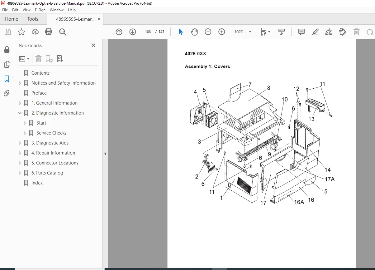
Assembly 1: Covers
- External covers and panels
- Access doors
- Shield assemblies
Assembly 2: Frame
- Main chassis components
- Structural elements
- Mounting brackets
Assembly 3: Printhead
- Laser scanning assembly
- Optical components
- Motor and mirrors
Assembly 4: Paper Feed Input Tray
- Tray components
- Paper guides
- Lift mechanisms
Assembly 5: Paper Feed Frame
- Feed rollers
- Separation mechanisms
- Drive gears
Assembly 6: Fuser
- Fuser assembly components
- Heating elements
- Temperature sensors
- Pressure rollers
Assembly 7: Electronics
- Circuit boards
- Power supplies
- Controllers
- Interface cards
Assembly 8: Transfer Assembly
- Transfer corona
- Charging components
- Cleaning mechanisms
Assembly 9: Option – Second Paper Drawer
- Optional tray components
- Sensors and mechanisms
- Installation hardware
Assembly 10: Options
- Memory modules
- Interface cards
- Accessories
Assembly 11: Miscellaneous
- Cables and harnesses
- Fasteners
- Small parts
Each assembly includes:
- Exploded view diagrams
- Part numbers
- Descriptions
- Quantities
KEY FEATURES OF THIS MANUAL
✓ 143 pages of official Lexmark factory documentation
✓ Complete error code reference with troubleshooting procedures
✓ Comprehensive service checks for all major components
✓ Step-by-step disassembly procedures with screw identification
✓ Detailed connector pinouts for all boards and components
✓ POST diagnostics with symptom tables
✓ Print quality troubleshooting guide
✓ Illustrated parts catalog with exploded views
✓ Configuration mode documentation
✓ ESD protection procedures
✓ Adjustment procedures with specifications
✓ Laser safety information (Class I certification)
✓ Power supply testing procedures
✓ Fuser operation timing and control
LEXMARK OPTRA E SPECIFICATIONS
Printer Type:
- Monochrome laser printer
- Electrophotographic print technology
- Personal/workgroup printing
Key Features:
- Fast print speeds
- High-resolution output
- Reliable paper handling
- Optional second paper tray
- Parallel interface standard
- Memory expandable
- Network-ready (with optional card)
WHO NEEDS THIS MANUAL?
- Authorized Lexmark Service Technicians
- Independent Printer Repair Shops
- Corporate IT Support Teams
- Office Equipment Maintenance Personnel
- Printer Refurbishment Specialists
- Technical Training Centers
- Multi-Vendor Service Organizations
- Electronics Technicians
CRITICAL SERVICE PROCEDURES INCLUDED
Diagnostics:
- POST error code interpretation
- Service error code analysis
- Symptom-based troubleshooting
- Component-level diagnostics
- Hex trace communication analysis
Component Replacement:
- Power supply replacement (LVPS, HVPS)
- Fuser assembly service
- Printhead removal and installation
- Transfer corona replacement
- Engine board replacement
- Controller board replacement
Testing:
- Low voltage power supply testing (all voltages)
- High voltage measurements
- Sensor verification
- Motor operation testing
- Parallel port diagnostics
- Memory testing
Adjustments:
- Print registration calibration
- Paper feed timing
- Fuser temperature control
Print Quality:
- Background elimination
- Streak troubleshooting
- Density correction
- Registration adjustment
- Transfer optimization
INSTANT DOWNLOAD – GET PRINTERS RUNNING FAST
Stop printer downtime immediately! This official Lexmark factory service manual gives you instant access to complete diagnostic procedures, error code explanations, and component-level repair instructions for the Optra E 4026 series. Whether you’re troubleshooting power supply failures, replacing the fuser assembly, diagnosing print quality issues, or performing preventive maintenance, you’ll have the exact same technical documentation used by Lexmark authorized service centers. Download now and restore your Lexmark laser printers to full operation with professional-grade factory specifications and procedures!
Pricing Rationale
This is a comprehensive 143-page official factory service manual for the Lexmark Optra E 4026 series laser printer – a professional-grade business laser printer widely deployed in offices and corporate environments. Official manufacturer service manuals for laser printers typically cost $60-120+ from Lexmark. This manual provides complete technical documentation including detailed error code tables, comprehensive component-level service checks (power supply testing, fuser diagnostics, print quality troubleshooting), step-by-step disassembly procedures, complete connector pinouts, and illustrated parts catalogs. The professional technical content, official factory status, and specialized diagnostic information justify professional pricing. At $26.95, this represents excellent value for printer technicians, IT departments, and repair shops who need immediate access to complete factory documentation to minimize equipment downtime and perform professional-level repairs on Lexmark laser printing equipment.