LG T1 Laptop Service Manual PDF DOWNLOAD
Original price was: $85.00.$18.95Current price is: $18.95.
Complete 114-page technical service manual for LG T1 laptop computers featuring Intel Core Duo processors. Comprehensive guide covering specifications, component locations, BIOS setup, symptom diagnosis, FRU replacement procedures, complete disassembly instructions, part lists, exploded views, and troubleshooting for professional laptop repair technicians.
Description
LG T1 Laptop Service Manual Technical Repair Guide Intel Core Duo Notebook – PDF DOWNLOAD
DESCRIPTION:
This comprehensive LG T1 Service Manual provides complete technical documentation for servicing and repairing LG T1 notebook computers. This 114-page professional manual is essential for electronics technicians, laptop repair shops, and service centers working on these Intel Core Duo-based laptops from LG Electronics.
System Covered
This technical service manual covers the LG T1 laptop series with the following specifications:
Processor (CPU):
- Intel Core Duo (Yonah architecture)
- Speed range: 1.66 GHz to 2.16 GHz
- Package: μFCPGA (Micro Flip Chip Pin Grid Array)
- Low voltage variants: 1.4 GHz available
- 667 MHz Front Side Bus (FSB)
Chipset & Graphics Options:
Configuration 1 (Integrated Graphics):
- Main chipset: Intel 945GM
- South bridge: Intel ICH7-M
- Graphics: Intel integrated graphics
Configuration 2 (Discrete Graphics):
- Main chipset: Intel 945PM
- South bridge: Intel ICH7-M
- Graphics: NVIDIA GeForce GO 7300/7400/7600
- VRAM: 64MB/128MB/256MB options
Memory:
- Slots: 2 x SODIMM
- Type: DDR2 PC2-4200S/5300S
- Speed: 533 MHz / 667 MHz capable
- Expandable configuration
Display Options:
- XGA: 185 nit brightness
- SXGA+: 200 nit brightness
- Built-in webcam (optional on some models)
Storage:
- HDD: 2.5″ 9.5mm height
- Capacities: 80GB/100GB
- Interface: SATA or PATA (Parallel ATA) type
Optical Drive:
- Fixed optical storage
- DVD-Combo or DVD Super Multi
- Emergency eject hole included
Communication:
- Modem: Daughter card type
- Ethernet: Agere Gigabit Ethernet controller (onboard)
- Wireless LAN: 802.11 b/g or a/b/g, Mini PCI-Express type
- Bluetooth: Version 2.0 (optional)
- Hexa-band antenna for wireless
Card Slots:
- Express Card Slot or Cardbus Card Slot (PCMCIA)
- 5-in-1 Card Reader:
- Memory Stick
- Memory Stick Pro
- MultiMediaCard (MMC)
- SD Card
- xD Picture Card
Ports and Connectors:
- Video: VGA output, S-Video (4-pin compatible)
- USB: 3 x USB 2.0 ports
- Network: RJ45 (Ethernet), RJ11 (Modem)
- Audio: Headphone-out/SPDIF, Microphone-in, Line-in
- IEEE 1394: FireWire port
- Power: AC-in connector (19V)
Input Devices:
- Keyboard: 86-key layout
- Touchpad with buttons
- Fingerprint Scanner: Authentic Fingerprint device (optional)
Special Buttons:
- Power button
- Direct Media button – Launch media programs with system off/standby
- Volume Down button
- Volume Up button
- SRS button – SRS WOW XT and TrueSurround XT audio enhancement
Indicators (LED):
- AC-in
- Power On
- Battery Charge
- HDD Activity
- Caps Lock
- Num Lock
- Wireless LAN/Bluetooth
Audio:
- Codec: Realtek ALC880 Azalia Audio
- Speakers: Stereo, 1 Watt each
- Built-in Microphone
- SRS WOW XT – Field effect enhancement
- SRS TrueSurround XT – Virtual 5.1 channel surround from 2 channels
Power:
- AC Adapter: 90 Watt, 19V 4.74A output
- Battery: 6-cell, 5.2 AHr, Cylindrical (Li-Ion)
Physical:
- Weight: Varies by configuration
- Security: Kensington security keyhole
Complete Manual Contents
Chapter 1: Service Information
- 1-1. Important Service Information:
- Strategy for replacing parts (FRU – Field Replaceable Units)
- Pre-replacement checklist
- Systematic troubleshooting approach
- Avoid unnecessary part replacement
- BIOS configuration preservation
- Strategy for hard disk drive replacement
- User data protection protocols
- 1-2. Safety Notices:
- Pre-service safety checks
- Screw and small parts verification
- Standby battery handling (nickel-cadmium content)
- Battery pack safety warnings
- LCD fluid exposure precautions
- Inverter card safety
- Main battery safety
- Cable disconnection procedures
- 1-3. Safety Information:
- General safety guidelines
- Housekeeping during maintenance
- Proper lifting techniques
- Weight limits (16kg/35lb maximum)
- Customer safety considerations
- Tool box placement
- Clothing and jewelry restrictions
- Safety glasses requirements
- Shield and guard reinstallation
- Electrical conductor safety
- 1-4. Laser Compliance Statement:
- CD-ROM/DVD drive safety
- Laser radiation exposure warnings
- Service restrictions for optical drives
- Visible and invisible laser radiation hazards
- 1-5. Backup (Standby) RTC Battery Safety Information:
- Battery replacement procedures
- Disposal requirements
- 1-6. Read This First:
- Certification requirements for service personnel
- FRU replacement guidelines
- Nylon-coated screw usage
- Drive sequence precautions
- Model-specific part replacement
- Part number verification
- Single failure analysis
- Non-defective FRU protection
- Warranty coverage determination
- Non-warranted damage examples
- Damage symptom identification
Chapter 2: Locations
- Front View:
- Wireless LAN/Bluetooth antenna location
- LCD monitor
- Keyboard layout
- Touchpad and buttons
- Built-in microphone
- Stereo speakers
- 5-in-1 card slot
- Fingerprint scanner location
- Direct Media button
- Volume controls
- SRS button
- Power button
- Rear View:
- Security keyhole
- S-Video connector (4-pin)
- Modem connector (RJ11)
- LAN connector (RJ45)
- Power connector
- Left View:
- USB connectors (2)
- Fan louvers/vents
- VGA connector
- IEEE 1394 connector
- Line-in / S/PDIF connector
- Headphone connector
- Microphone connector
- Right View:
- Express Card slot
- Optical disk drive
- Disk tray button
- Emergency eject hole
- USB connector
- Bottom View:
- Battery compartment
- Memory access panel
- Hard drive access
- Model/serial number label location
Chapter 3: System Information
- Specification:
- Complete technical specifications (detailed above)
- Component configurations
- Optional equipment variations
- System Block Diagram:
- Overall system architecture
- Chipset interconnections
- CPU core connections (V1.05S, V1.8, V0.9S voltages)
- GMCH (Graphics and Memory Controller Hub) – 945GM/945PM
- ICH7-M (I/O Controller Hub) connections
- PCI Express x4 DMI interface
- Memory controller (DDR2 667MHz)
- Graphics controller connections
- Power delivery system
- ACIN and charger circuit
- Voltage regulators (V1.8, V3A, V5, V3S, V1.05S, V1.5S)
- Audio codec (ALC880) connections
- Embedded controller (H8S/2110B)
- TPM (Trusted Platform Module) AT97SC3202
- Ethernet controller connections
- Cardbus controller (PCI7412)
- Express Card interface
- PATA HDD connection
- ODD (Optical Disk Drive) interface
- PCIe Mini Card slot
- Fan control
- LCD connector
- CRT connector
- Thermal sensor
- Acceleration sensor
- Internal peripherals (keyboard, touchpad, speakers, microphone)
- Fn Key Combinations:
- Function key shortcuts
- Hot key operations
- System control combinations
- Status Indicators:
- LED function descriptions
- Indicator light meanings
- Status interpretation guide
- BIOS Flash:
- BIOS update procedures
- Flash utility usage
- Recovery procedures
- BIOS Setup:
- Entering BIOS setup
- Navigation instructions
- Main menu options
- Advanced settings
- Security settings
- Boot options
- Exit procedures
- Setup utility key descriptions
- Default configuration loading
- Configuration save procedures
- Processor information display
- Memory size display
- UUID display
- Battery information access
- TPM (Trusted Platform Module):
- TPM functionality
- Security features
- Configuration procedures
Chapter 4: Symptom-to-Part Index
- Power System Checkout:
- Power-on failures
- Battery charging problems
- AC adapter issues
- Power indicator problems
- Standby/hibernation failures
- Numeric Error Codes:
- 0281: Memory size mismatch (POST detected different size)
- Error code interpretation
- Resolution procedures
- Error Messages:
- System error messages
- Diagnostic messages
- Recovery procedures
- LCD-Related Symptoms:
- Nothing displayed on LCD screen
- Wrong colors displayed
- Horizontal or vertical lines
- Backlight failures
- Inverter problems
- LCD cable issues
- Video memory errors
- Indeterminate Problems:
- Intermittent failures
- Random system behavior
- Thermal issues
- Systematic diagnosis approach
Chapter 5: Removing and Replacing a Part (FRU)
Complete disassembly procedures with step-by-step instructions:
- Battery Pack Removal
- Bottom Case Disassembly
- Memory Module Replacement (1050):
- SODIMM removal procedure
- Memory slot access
- Installation procedures
- Hard Disk Drive (HDD) Removal
- Optical Disk Drive (ODD) Replacement
- Wireless LAN Card Removal
- Keyboard Removal (Keydeck 1060):
- Keyboard connector disconnection
- Careful removal to avoid damage
- Touchpad Assembly
- Top Cover Removal
- Display Module (1120) Removal:
- Display connector disconnection
- Hinge removal
- LCD panel separation
- Inverter card removal
- LCD cable routing
- LCD Panel Replacement
- Inverter Card Replacement
- Webcam Removal (if equipped)
- Motherboard (System Board) Removal:
- All cable disconnections
- Component removal sequence
- Screw locations
- Proper handling procedures
- CPU Removal and Replacement:
- Heatsink removal
- Thermal paste application
- Processor installation
- Cooling Fan and Heatsink Assembly
- CMOS Battery Replacement
- Power Jack Repair
- DC-IN Board Replacement
Each removal procedure includes:
- Required tools
- Step numbers and sequences
- Warning notices
- Connector identification
- Screw locations and types
- Cable routing instructions
- Reassembly notes
Chapter 6: Part List
- Part List:
- Complete FRU part numbers
- Component descriptions
- Model-specific part variations
- Ordering information
- Alternative part numbers
- Component specifications
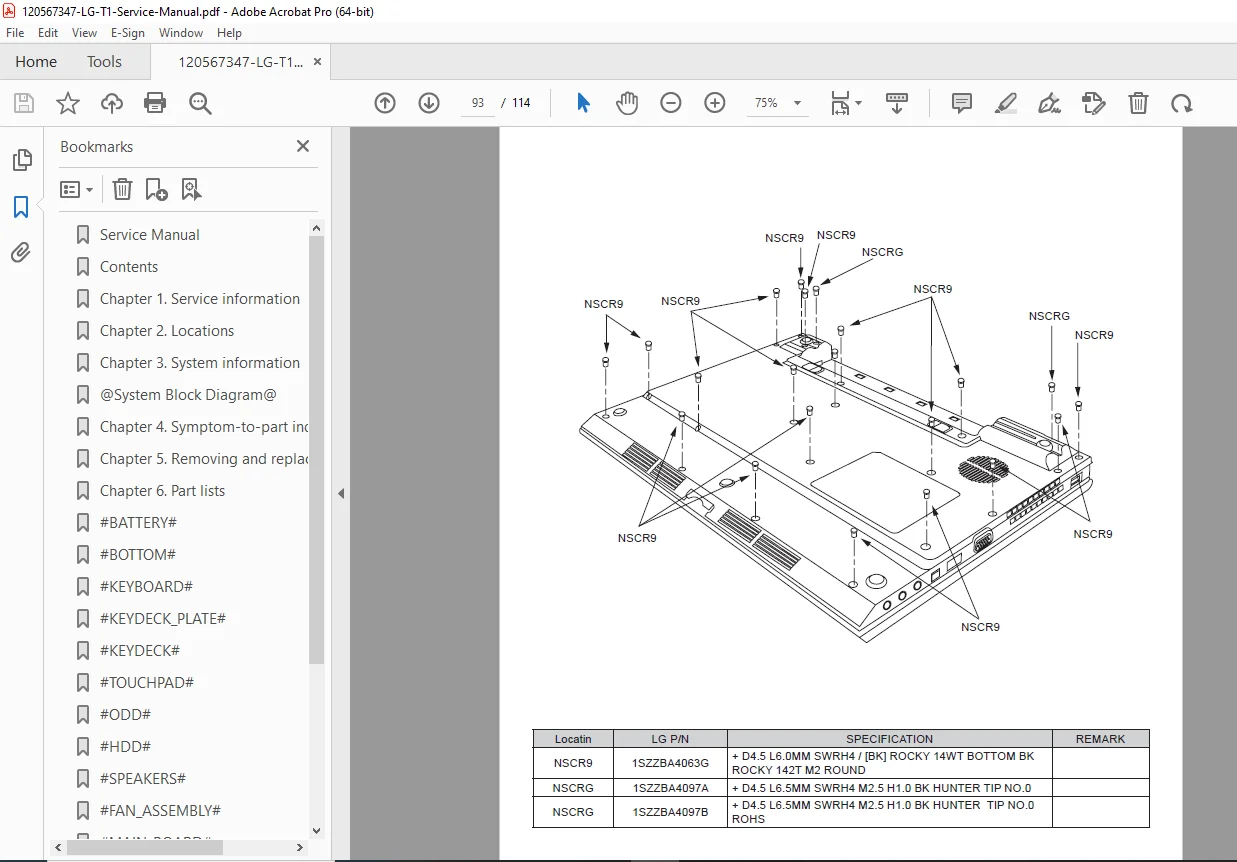
- Exploded View:
- Detailed exploded diagrams
- Assembly relationships
- Screw locations marked
- Part number callouts
- Multiple angle views
- Subassembly breakdowns
Key Features of This Service Manual
✓ Official LG Electronics documentation – Factory authorized service information ✓ 114 comprehensive pages with detailed procedures and diagrams ✓ Intel Core Duo coverage – Yonah processor family (1.66-2.16 GHz) ✓ Multiple configurations – Both integrated and discrete graphics options ✓ Complete disassembly guide – Step-by-step FRU replacement procedures ✓ System block diagram – Detailed chipset and component interconnections ✓ BIOS setup guide – Complete setup utility documentation ✓ Troubleshooting procedures – Symptom-to-part diagnosis ✓ Error code reference – Numeric codes and error messages ✓ Safety information – Comprehensive warnings and precautions ✓ Part lists with exploded views – Easy part identification ✓ Warranty guidelines – Covered and non-covered damage examples
Who Should Use This Manual
This LG T1 service manual is designed for:
- Professional laptop repair technicians
- Computer service centers
- LG authorized service providers
- Electronics repair shops
- Technical schools and training programs
- IT department maintenance personnel
- Experienced hobbyist laptop repair enthusiasts
Important Service Notes
Certification Requirements:
- LG recommends only trained, certified personnel service these computers
- Improper service may void warranty
- Follow all safety procedures
FRU Replacement Strategy:
- Use systematic troubleshooting before replacing parts
- Reinstall original part if replacement doesn’t solve problem
- Test single components before replacing entire assemblies
- Note BIOS configurations before service
- Verify original settings after service completion
Safety Critical Items:
- Battery packs contain nickel and must be disposed properly
- LCD fluid requires immediate washing if contact occurs
- Inverter cards have shock hazards
- Laser assemblies in optical drives
- ESD precautions required for all internal service
Warranty Considerations:
Not Covered Under Warranty:
- Cracked LCD panels from excessive force
- Scratched cosmetic parts
- Liquid damage
- Broken plastic from excessive force
- Foreign material damage
- Improper PC Card installation damage
- Blown fuses from unsupported devices
- Forgotten passwords
- Sticky keys from liquid spills
Model Variations:
- Specifications may vary by model configuration
- Verify exact model before ordering parts
- Check model name on ID label: “M/N: LMXX-XXXX”
- Some features are optional (Bluetooth, Fingerprint, Webcam)
Special Features:
- Direct Media button works with system off/standby/hibernation
- SRS audio enhancement requires button activation
- 5.1 channel virtual surround from 2-channel audio
- Fingerprint security when equipped
- TPM security chip for data encryption
Common Repair Procedures Covered
- Screen replacement – LCD panel and inverter service
- Keyboard replacement – Complete keydeck removal
- Memory upgrades – DDR2 SODIMM installation
- Hard drive replacement – SATA/PATA drive service
- Optical drive replacement – DVD-Combo/Super Multi
- Wireless card upgrade – Mini PCI-Express installation
- Battery replacement – 6-cell Li-Ion pack
- Cooling system service – Fan and heatsink cleaning
- Motherboard replacement – Complete system board R&R
- Power jack repair – DC-IN board replacement
Manual Quality and Format
- Format: Professional PDF document
- Pages: 114 pages of comprehensive technical content
- Graphics: High-quality diagrams, photos, exploded views
- Organization: Logical chapter structure with clear contents
- File size: 12.9 MB – Detailed illustrations
- Publisher: LG Electronics – Official factory documentation
- Print-friendly: Standard page size suitable for printing
This LG T1 Service Manual PDF provides complete technical documentation essential for professional service and repair of these Intel Core Duo-based LG notebook computers from the mid-2000s era.
FILE DETAILS:
| Manual Type | Technical Service Manual |
|---|---|
| Model Covered | LG T1 Notebook Computer |
| Processor | Intel Core Duo (Yonah) 1.66-2.16 GHz |
| Year | 2006 Edition (February 21, 2006) |
| Pages | 114 pages |
| PDF Quality | Excellent – Original manufacturer document |
| File Size | 12.9 MB |
| Language | English |
| Publisher | LG Electronics |
| Author | Kim Kang-il (LG Electronics) |