Lg Wm3070hwa Service Manual Repair Guide – PDF Download
Original price was: $37.95.$21.95Current price is: $21.95.
Lg Wm3070hwa Service Manual Repair Guide
Description
Lg Wm3070hwa Service Manual Repair Guide
FILE DETAILS:
Lg Wm3070hwa Service Manual Repair Guide
LANGUAGE:ENGLISH
PAGES:61
DOWNLOADABLE:YES
FILE TYPE:PDF
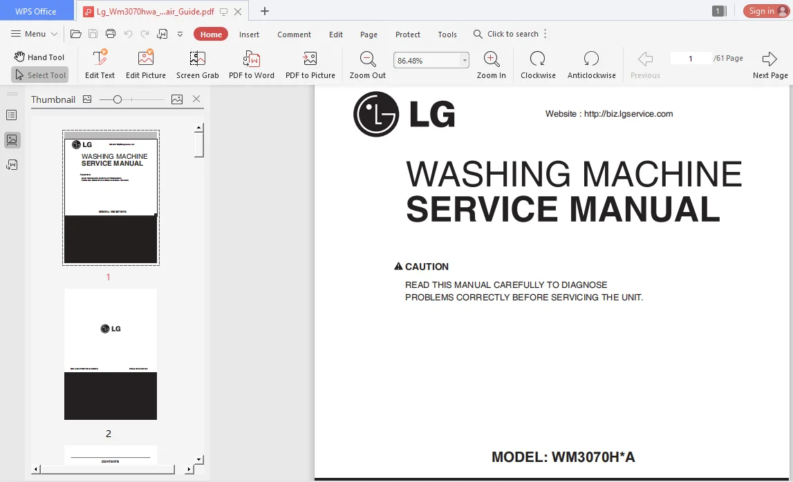
LG WM3070HWA SERVICE MANUAL REPAIR GUIDE – PDF DOWNLOAD:
IMAGES PREVIEW OF THE MANUAL:
SAMPLE PAGE FROM THE MANUAL:
Lg Wm3070hwa Service Manual Repair Guide
1. Unplug power cord.
2. Remove rear panel.
3. Remove washer top.
4. Remove main PCB assembly cover as shown in figure below.
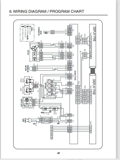
5. Locate the white hall sensor 4-wire connector using wiring diagram wire colors as your guide.
6. Plug in power cord, close door, and press the button. DO NOT PRESS START!
7. Place meter leads on White & Gray wires. You should read 10 to 15 VDC output from the Main PCB Assembly to the Hall sensor. If no 10 to 15 VDC is measured, the control board is defective.
8. Place meters leads on Blue to Gray. Turn motor rotor slowly by hand. You should measure a pulsing 10 VDC. Place meter leads on Red to Gray. Turn motor rotor slowly by hand. You should measure a pulsing 10 VDC. If both tests measure a pulsing 10 VDC, hall sensor and harness OK. If either or both tests measures 9 to 10 volts, but does not pulse or change, Hall sensor has failed and must be replaced. IF zero (0) voltage is measured on either test, check red blue wires for continuity. Repair or replace harness as needed.
TABLE OF CONTENTS:
Lg Wm3070hwa Service Manual Repair Guide
1 Specifications 5
2 Features and Technical Explanation 6-8
3 Parts Identification 9
4 Installation and Test 10-12
5 Operation 13-19
5-1 Control Panel Features 13-15
5-2 Cycle Guide 16
5-3 Special Functions 17
5-4 Explanation of Each Process 18-19
6 Wiring Diagram / Program Chart 20-21
7 Test Mode 22
7-1 Safety Caution 22
7-2 Load Test Mode 22
7-3 How To Read the Display in Load Test Mode 23
7-4 How To Check the Water Level Frequency and Vibration Sensor Error 23
8 Troubleshooting 24-39
8-1 Safety Caution 24
8-2 Error Mode Summary 24-25
8-3 Troubleshooting Summary 26
8-4 Troubleshooting With Error 27-33
8-5 Troubleshooting Else 34-39
9 Component Testing Information 40-54
9-1 Filter Assembly (Line Filter) 40
9-2 Door Look Switch Assembly 41-42
9-3 Stator Assembly 43-45
9-4 Pump Motor Assembly 46
9-5 Inlet Valve Assembly 47
9-6 Heater Assembly 48
9-7 Thermistor Assembly 49-50
9-8 Steam Generator Assembly 51-52
9-9 Lamp 53
9-10 Vibration sensor assembly 54
10 Disassembly Instructions 55-65
11 Exploded View 66-68
11-1 Cabinet and Control Panel Assembly 66
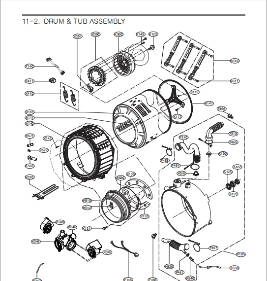
11-2 Drum and Tub Assembly 67
11-3 Dispenser Assembly 68
PLEASE NOTE:
⦁ This is the same manual used by the dealers to diagnose and troubleshoot your vehicle
⦁ You will be directed to the download page as soon as the purchase is completed. The whole payment and downloading process will take anywhere between 2-5 minutes
⦁ Need any other service / repair / parts manual, please feel free to contact [email protected] . We still have 50,000 manuals unlisted