Liebherr A 900 C ZW Litronic 1033 Hydraulic Excavator Operator’s Manual SN 37728 – PDF DOWNLOAD
$28.95
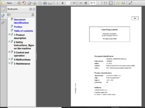
Liebherr A 900 C ZW Litronic 1033 Hydraulic Excavator Operator’s Manual SN 37728 – PDF DOWNLOAD
Product ID
Manufacturer: Liebherr-Hydraulikbagger GmbH
Type: A 900 C ZW Litronic
Type no.: 1033
From Serial no.: 37728
Description
Liebherr A 900 C ZW Litronic 1033 Hydraulic Excavator Operator’s Manual SN 37728 – PDF DOWNLOAD
FILE DETAILS:
Liebherr A 900 C ZW Litronic 1033 Hydraulic Excavator Operator’s Manual SN 37728 – PDF DOWNLOAD
Language : English
Pages : 320
Downloadable : Yes
File Type : PDF
DESCRIPTION:
Liebherr A 900 C ZW Litronic 1033 Hydraulic Excavator Operator’s Manual SN 37728 – PDF DOWNLOAD
Product ID
Manufacturer: Liebherr-Hydraulikbagger GmbH
Type: A 900 C ZW Litronic
Type no.: 1033
From Serial no.: 37728
Preface:
These operating instructions have been written for the machine operator and for the maintenance personnel of the machine.
They contain:
The operating instructions are to be read and used carefully by all persons who carry out work with or on the machine before putting the machine into service for the first time and later, at regular intervals.
Work with or on the machine includes, for example:
- Operation including setting up and equipping, rectifying malfunctions during the course of work, resolving production dropouts, care, disposal of operating and process materials.
- Maintenance, including maintenance, inspection and repair work.
- Transportation or loading the machine.
The operating instructions allow the machine operator to familiarize themselves with the machine more easily and prevent malfunctions occurring due to improper operation. The observance of the operating and maintenance instructions by maintenance personnel:
- increases reliability in use.
- extends the service life of your machine.
- reduces repair costs and downtime.
The operating instructions belong with the machine for the entire lifetime of the machine. Place a copy in an easily reached position on the cab storage shelf. This copy must be replaced immediately if lost, damaged or unreadable.
The operating and maintenance instructions must be completed by information on current national regulations for accident prevention and protection. In addition to the operating instructions and legally binding regulations on accident prevention which apply in the user country and at point of use, authorized specialist rules for safe and correct working procedures are also to be observed.
These operating and maintenance instructions contain all the information required for operating and maintaining your machine.
- Some illustrations in these operating instructions may depict details and working devices which differ from your machine.
- In some illustrations, protective devices and covers have been removed in the interests of better presentation.
- Improvements, which are always being incorporated into our machines, may result in changes to your machine which are not yet indicated in these operating instructions.
IMAGES PREVIEW OF THE MANUAL:
TABLE OF CONTENTS:
Liebherr A 900 C ZW Litronic 1033 Hydraulic Excavator Operator’s Manual SN 37728 – PDF DOWNLOAD
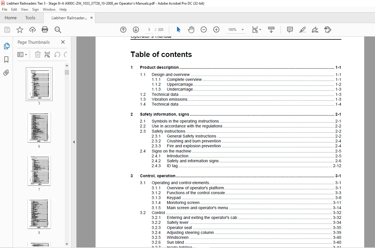
1 Product description 1-1
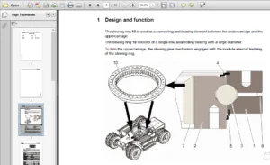
1 1 Design and overview 1-1
1 1 1 Complete overview 1-1
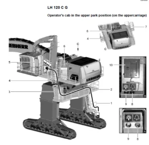
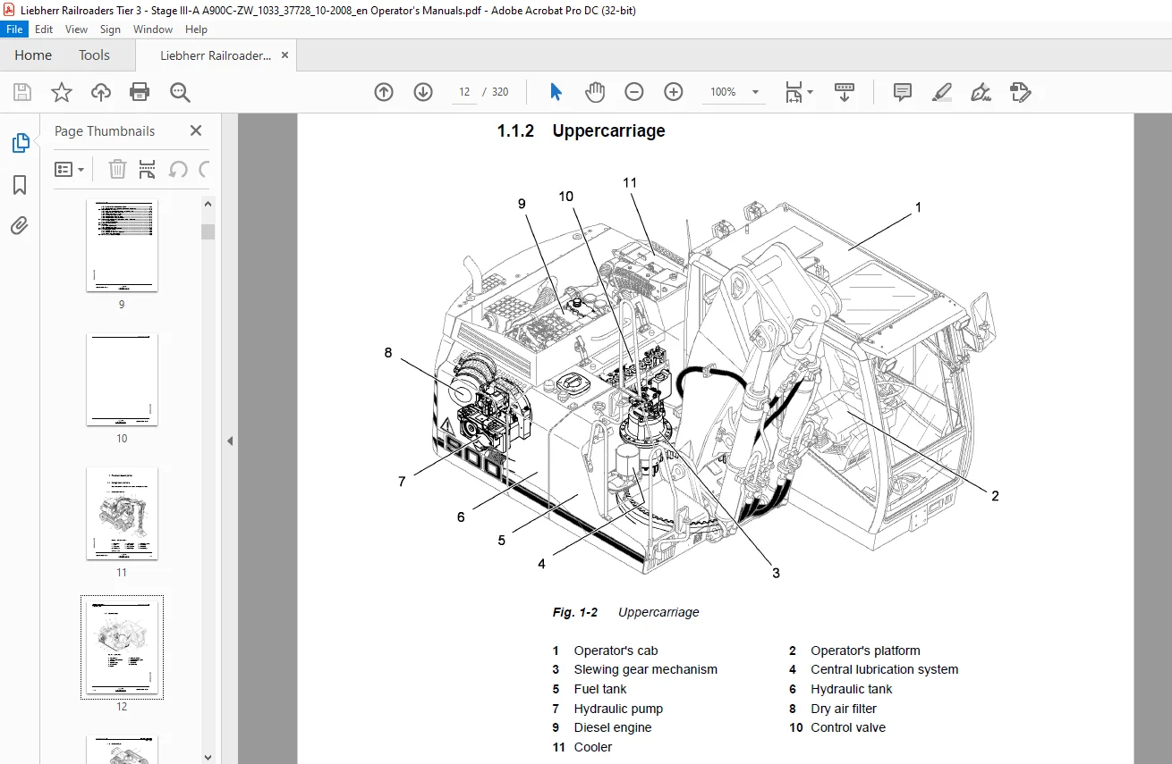
1 1 2 Uppercarriage 1-2
1 1 3 Undercarriage 1-3
1 2 Technical data 1-3
1 3 Vibration emissions 1-3
1 4 Technical data 1-4
2 Safety information, signs 2-1
2 1 Symbols in the operating instructions 2-1
2 2 Use in accordance with the regulations 2-2
2 3 Safety instructions 2-2
2 3 1 General Safety instructions 2-2
2 3 2 Crushing and burn prevention 2-4
2 3 3 Fire and explosion prevention 2-4
2 4 Signs on the machine 2-5
2 4 1 Introduction 2-5
2 4 2 Safety and information signs 2-6
2 4 3 ID tag 2-12
3 Control, operation 3-1
3 1 Operating and control elements 3-1
3 1 1 Overview of operator’s platform 3-1
3 1 2 Functions of the control console 3-3
3 1 3 Keypad 3-8
3 1 4 Monitoring screen 3-11
3 1 5 Main screen and operator’s menu 3-14
3 2 Control 3-32
3 2 1 Entering and exiting the operator’s cab 3-32
3 2 2 Safety lever 3-34
3 2 3 Operator seat 3-35
3 2 4 Adjusting steering column 3-39
3 2 5 Windscreen 3-40
3 2 6 Sun blind 3-40
3 2 7 Inside lighting 3-41
3 2 8 Windscreen wiper 3-41
3 2 9 Illumination 3-43
3 2 10 Heating and air-conditioning system 3-45
3 2 11 Emergency hammer 3-50
3 3 Operation 3-51
3 3 1 Safety instructions 3-51
3 3 2 Starting machine 3-52
3 3 3 Switching off the diesel engine 3-58
3 3 4 Starting aids 3-59
3 3 5 Travel operation 3-61
3 3 6 On-road travelling 3-64
3 3 7 Oscillating axle locking device 3-65
3 4 Working with the machine 3-67
3 4 1 Working with the machine safely 3-67
3 4 2 Sensor controlled low idle automatic 3-71
3 4 3 Locking uppercarriage 3-72
3 4 4 Rotating the uppercarriage 3-72
3 4 5 Braking the uppercarriage 3-73
3 4 6 Working position 3-74
3 4 7 Operating the working tool 3-75
3 4 8 Lowering of the working tool when engine is shut off 3-78
3 4 9 Moving boom 3-78
3 4 10 Choosing attachment and operating mode 3-79
3 4 11 Attachment operation 3-80
3 4 12 Operation of swivel rotator (optional equipment) 3-85
3 4 13 Turning, swivelling locking and releasing attachment 3-87
3 4 14 Magnet system for the operation of hydromagnets (optional equipment) 3-88
3 4 15 Socket on stick (optional equipment) 3-89
3 5 Working with the ZW system 3-90
3 5 1 ZW control panel 3-91
3 5 2 Switch on ZW system 3-91
3 5 3 Re-railing the machine 3-92
3 5 4 Automatic travelling mode 3-95
3 5 5 Lighting 3-96
3 5 6 Emergency stop 3-96
3 5 7 Emergency Horn 3-96
3 5 8 Operating elements for the assistant 3-97
3 5 9 Rail travelling mode 3-97
3 5 10 Removing the machine from the rails 3-97
3 5 11 Coupling rail vehicles 3-100
3 5 12 Wagon brake system (optional equipment) 3-100
3 6 Stroke and boom limitation 3-106
3 6 1 Safety information 3-106
3 6 2 Functional description 3-106
3 6 3 Stroke and boom limitation menu 3-106
3 6 4 Application of lift limitation 3-108
3 6 5 Using boom limitation 3-108
3 6 6 Bridging stroke and boom limitation 3-109
3 6 7 Setting stroke limitation 3-111
3 6 8 Adjusting boom limitation 3-115
3 7 Installation and removal of attachment parts 3-118
3 7 1 Safe installation and removal of attachment parts 3-118
3 7 2 Safe removal and installation of attachment pins 3-119
3 7 3 Installation and removal of digging tool 3-120
3 7 4 Attachment of grapple to bucket stick 3-122
3 7 5 Hydraulic quick-change adapter (optional equipment) 3-125
3 7 6 Hydraulic quick-change adapter with LIKUFIX (optional equipment) 3-129
3 7 7 Mechanical quick-change adapter (optional equipment) 3-130
3 7 8 Mechanical quick-change bucket stick (optional equipment) 3-135
3 7 9 Quick-change adapter equipment at swivel rotator (optional equipment) 3-140
3 7 10 Assignment of the hydraulic lines 3-144
3 8 General working methods 3-145
3 8 1 Tips for the proper operation of the machine preventing damage and wear 3-145
3 8 2 Preparation 3-147
3 8 3 Working with the backhoe bucket 3-147
3 8 4 Loading transport vehicle 3-149
3 8 5 Grading work 3-149
3 8 6 Working with grapples 3-150
3 8 7 Excavating and moving material with grapples 3-151
3 8 8 Working with the hydraulic hammer 3-152
3 8 9 Load lifting operation 3-153
3 8 10 Use of quick-change adapter for load lifting operation 3-154
3 8 11 Overload Suspension System 3-154
3 9 Transport 3-160
3 9 1 Safely transporting the machine 3-160
3 9 2 Transportation on low-loader 3-160
3 9 3 Loading with crane 3-162
4 Malfunctions 4-1
4 1 Error code list 4-1
4 2 Faults and remedies 4-11
4 2 1 Diesel engine and fuel system 4-11
4 2 2 Hydraulic system 4-13
4 2 3 Travelling 4-15
4 2 4 Brakes 4-15
4 2 5 Electrical system 4-15
4 2 6 Heating and air conditioning system 4-16
4 2 7 Working attachment 4-16
4 2 8 ZW system 4-17
4 3 Fuses and relays 4-17
4 3 1 Fuse box E50 4-18
4 3 2 ESP02 printed circuit board 4-19
4 3 3 Fuse box of ZW system 4-20
4 3 4 Emergency hydraulics (optional equipment) 4-22
4 4 Emergency operation 4-22
4 4 1 Emergency mode control 4-23
4 4 2 Emergency operation of hydraulic pump 4-26
4 4 3 Emergency operation of servo control 4-27
4 4 4 Emergency operation of slewing gear brake 4-27
4 4 5 Emergency operation of stroke and boom limitation (optional equipment) 4-28
4 4 6 Travel emergency mode 4-30
4 4 7 Emergency hydraulics (optional equipment) 4-33
4 4 8 Emergency gear shifting 4-35
4 4 9 Towing the machine 4-36
4 4 10 Disengaging transmission (emergency release) 4-36
5 Maintenance 5-1
5 1 Safe maintenance of the machine 5-1
5 1 1 General safety instructions 5-1
5 1 2 Cleaning 5-1
5 1 3 Crack detection 5-2
5 1 4 Welding work 5-3
5 1 5 Fuels and lubricants 5-3
5 1 6 Repairs 5-3
5 1 7 Electrical system 5-4
5 1 8 Hydraulic accumulators 5-4
5 1 9 Hydraulic and other hoses 5-5
5 1 10 Cab protection (FOPS) 5-6
5 2 Access doors for maintenance 5-6
5 2 1 Overview of access doors 5-6
5 2 2 Door locking mechanism 5-7
5 2 3 Locking mechanism for bonnet 5-8
5 3 Tyres 5-8
5 3 1 Checking tyre pressure 5-8
5 3 2 Tyre inflating hose (optional equipment) 5-9
5 3 3 Foam tyres 5-10
5 3 4 Checking wheel lugs for proper fit 5-10
5 4 Lubricants and operating fluids 5-11
5 4 1 General information to change lubricants and operating fluids 5-11
5 4 2 Lubrication chart 5-13
5 4 3 Lubricant table 5-14
5 4 4 Fuels, lubricants and process chemicals 5-15
5 5 Specifications for fuels, lubricants and process chemicals 5-16
5 5 1 Diesel fuels 5-16
5 5 2 Lubricating oil for the diesel engine 5-17
5 5 3 Coolant for the diesel engine 5-18
5 5 4 Hydraulic oil 5-22
5 5 5 Grease and other process chemicals 5-27
5 6 Diesel engine 5-27
5 6 1 Checking the oil level in the diesel engine 5-27
5 6 2 Changing the diesel engine oil 5-28
5 6 3 Ribbed V-belt for A/C compressor and alternator installation 5-29
5 6 4 Crankcase bleeding point 5-30
5 6 5 Grease the starter tooth ring 5-30
5 7 Cooling system 5-31
5 7 1 Checking and cleaning the cooling system 5-31
5 7 2 Check coolant level 5-32
5 7 3 Changing coolant 5-32
5 7 4 Checking coolant, adjusting mixing ratio 5-34
5 8 Fuel system 5-38
5 8 1 Refuelling 5-38
5 8 2 Dewatering fuel tank 5-39
5 8 3 Emptying and cleaning fuel tank 5-40
5 8 4 Maintenance of fuel filter 5-41
5 8 5 Bleeding fuel system 5-43
5 9 Dry air filter 5-45
5 9 1 Cleaning the dust removal valve 5-46
5 9 2 Replacing filter elements 5-46
5 9 3 Checking the clean air line 5-48
5 10 Hydraulic system 5-48
5 10 1 Preparation 5-48
5 10 2 Check the oil level in the hydraulic tank 5-49
5 10 3 Releasing the pressure from the hydraulic system 5-49
5 10 4 Replacing breather filter 5-50
5 10 5 Emptying and refilling hydraulic tank 5-50
5 10 6 Return filter 5-52
5 10 7 Control oil filter 5-53
5 10 8 Control circuit 5-54
5 10 9 Bleeding of the hydraulic pumps 5-54
5 10 10 Removing the suction hose 5-55
5 10 11 Bypass oil filter (optional equipment) 5-55
5 10 12 Servicing the hydraulic cylinder 5-57
5 10 13 Replacing hydraulic hoses 5-58
5 11 Changing the oil on components 5-58
5 11 1 General notes 5-58
5 11 2 Swin gear – oil change 5-59
5-60
5 11 4 Steering and rigid axle – oil change 5-60
5-61
5 11 6 Pump distributor gear – oil change 5-62
5-62
5 13 Electrical system 5-63
5 13 1 Notes regarding the electrical system 5-63
5 13 2 Battery main switch 5-63
5 13 3 Battery care 5-64
5 13 4 Slip ring body 5-65
5 14 Heating and air-conditioning system 5-66
5 14 1 Recirculated and ambient air filter 5-66
5 14 2 Heating system 5-67
5 14 3 air-conditioning system 5-67
5 15 Automatic lubrication of the machine 5-69
Operator’s manual
5 11 3 Transmission – oil change
5 11 5 Wheel head – oil change
5 12 Brake disks – wear measurement
5 15 1 Semi-automatic central lubrication system 5-69
5 15 2 Fully automatic central lubrication system (optional equipment) 5-71
5 16 Manual lubrication of the machine 5-72
5 16 1 Lubricating steering knuckle bearings and oscillating bolts 5-73
5 16 2 Digging buckets / bucket tilting device 5-73
5 16 3 Attachments (optional equipment) 5-74
5 16 4 Hydraulic quick change adapter 5-74
5 16 5 Mechanical quick-change adapter 5-75
5 16 6 Mechanical quick-change bucket stick 5-76
5 17 Couplings of the quick-change adapter systems (optional equipment) 5-76
5 17 1 Hydraulic coupling 5-76
5 17 2 LIKUFIX electric coupling 5-78
5 18 Parking and swing gear brake 5-78
5 19 ZW system 5-79
5 19 1 Lubricating rail chassis 5-79
5 19 2 Inspecting rail vehicle 5-79
5 20 Wagon brake system (optional equipment) 5-80
5 21 General Maintenance points 5-82
5 21 1 Replacing wear parts 5-82
5 21 2 Replacing the teeth on the digging tool 5-82
5 21 3 Welding work on the machine 5-83
5 22 Maintenance and inspection schedule 5-83
Questions? Email us: [email protected]
PLEASE NOTE:
- This is not a physical manual but a digital manual – meaning no physical copy will be couriered to you. The manual can be yours in the next 2 mins as once you make the payment, you will be directed to the download page IMMEDIATELY.
- This is the same manual used by the dealers inorder to diagnose your vehicle of its faults.
- Require some other service manual or have any queries: please WRITE to us at [email protected]
S.V