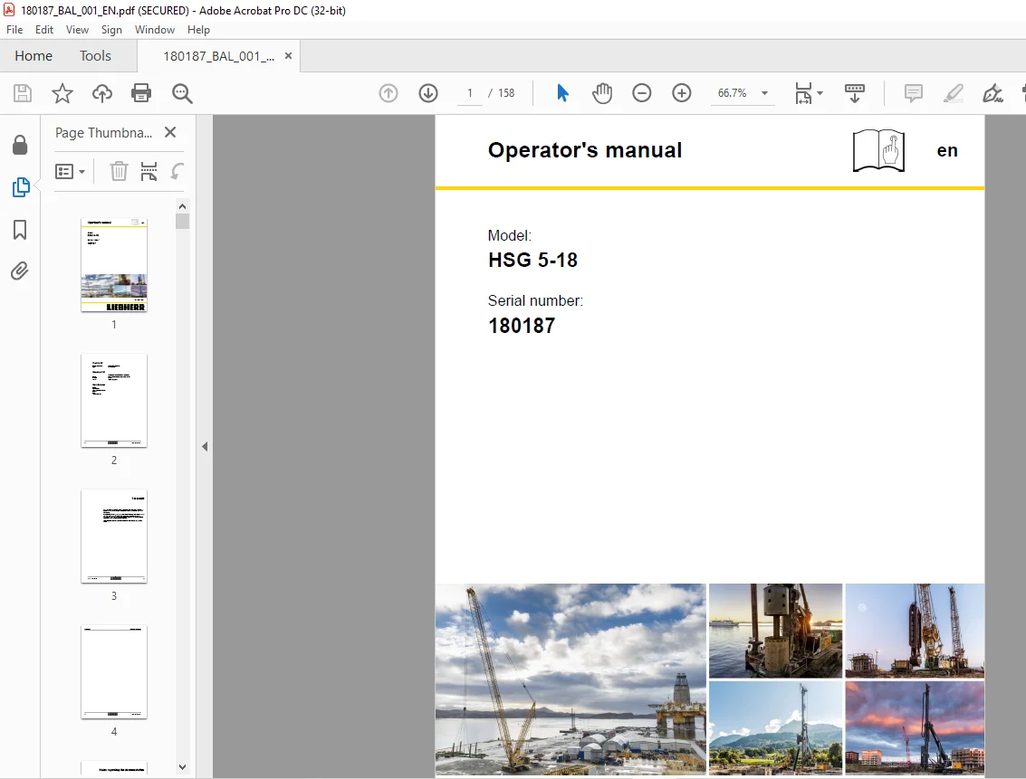
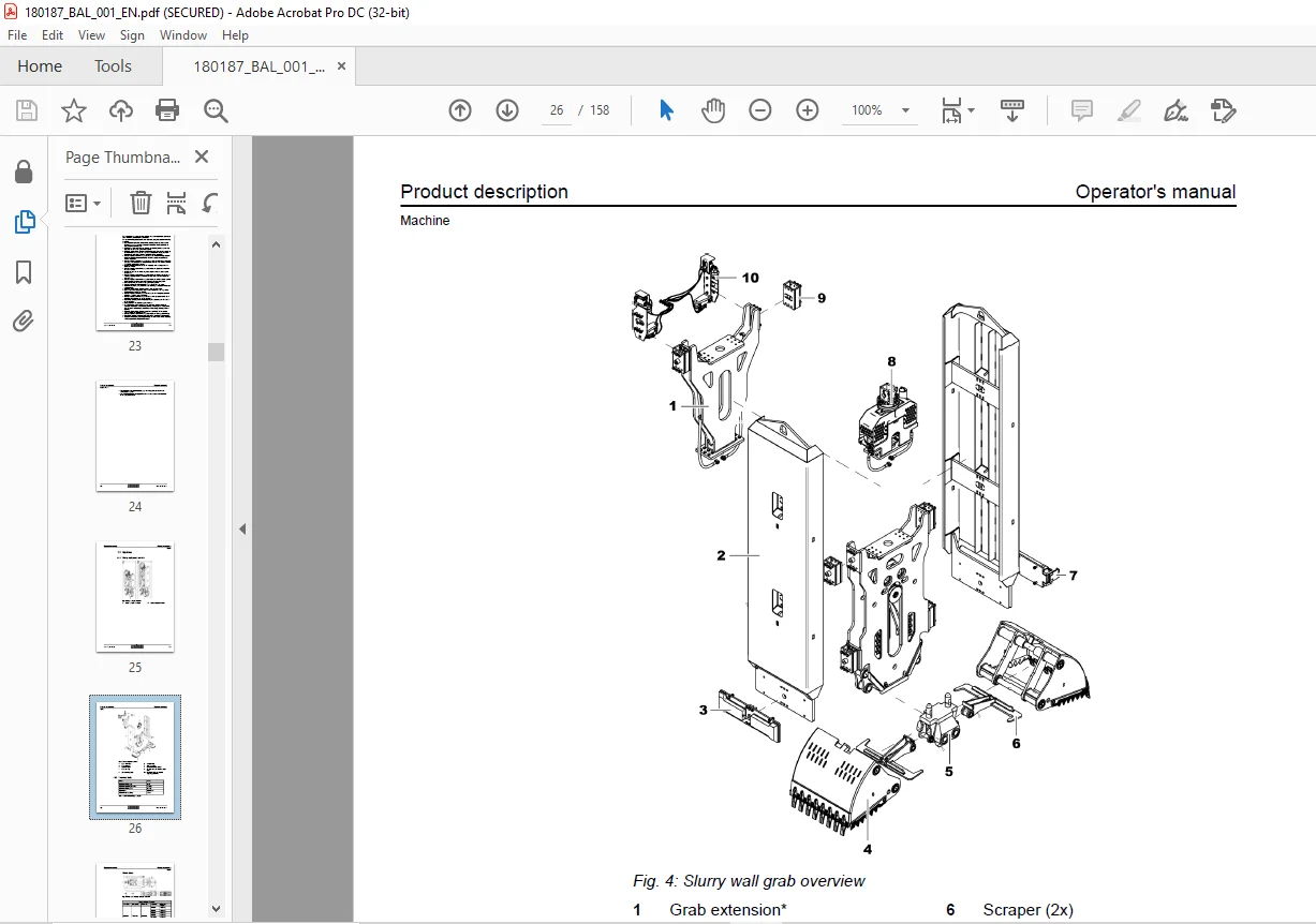
Liebherr Crane HSG 5-18 Operator’s Manual SN 180187 – PDF DOWNLOAD
$28.95
Liebherr Crane HSG 5-18 Operator’s Manual SN 180187 – PDF DOWNLOAD
Description
Liebherr Crane HSG 5-18 Operator’s Manual SN 180187 – PDF DOWNLOAD
FILE DETAILS:
Liebherr Crane HSG 5-18 Operator’s Manual SN 180187 – PDF DOWNLOAD
Language : English
Pages : 158
Downloadable : Yes
File Type : PDF
IMAGES PREVIEW OF THE MANUAL:
DESCRIPTION:
Liebherr Crane HSG 5-18 Operator’s Manual SN 180187 – PDF DOWNLOAD
Foreword:
- The name Liebherr doesn’t just stand for products and services. It has become a byword for ideas
and innovations. For progress which has proved its worth in the marketplace. - We constantly strive to extend and improve our diverse range of products and serv- ices. This
requires ongoing cooperation and sharing of experience with our customers and business partners
throughout the world. We are therefore grateful for any ideas and suggestions for improvements. - Inform Liebherr customer service if the machine is sold or bought by a previous owner.
Appropriate use:
- The supplied equipment determines the possible applications of the machine.
- The interchangeable equipment is designed and constructed exclusively for the appropriate use
stated and described in operator’s manual. - The interchangeable equipment may be operated exclusively in an admissible setup condition and in
the mode corresponding to the use. - Special machine tasks that deviate from the tasks described in the operator’s manual must be
coordinated with interchangeable equipment manufacturer before- hand.
The appropriate use of interchangeable equipment is a basic requirement of safe operation.
The non-observation of the appropriate machine use results in grave conse- quences:
– Life-threatening or fatal injuries
– Severe damage to interchangeable equipment, basic machine, assets or contamination of the
environment for which the manufacturer of interchangeable equipment cannot be held liable.
– Loss of warranty and guarantee claims
Utilization not described in operator’s manual must be authorized in writing by the manufacturer in
declaration of approval. Any other use of the machine without manufacturer’s written declaration of
approval is deemed inappropriate use.
The appropriate use of interchangeable equipment is exclusively defined as follows:
– Application in working ranges and under operating conditions listed and described in the
operator’s manual.
– Use of interchangeable equipment exclusively in deep foundation or similar applications listed
and described in operator’s manual.
The appropriate use of interchangeable equipment observing the following specifi- cations and
preconditions:
– All safety devices are installed and functioning properly.
– All preventive and corrective maintenance works stated in maintenance and inspection plan of
operator’s manual were performed according to specifications by maintenance personnel or Liebherr
service personnel.
– All safety regulations in this operator’s manual are observed.
– All valid national and international safety regulations (e.g. oil or gas industry) are observed
by the owner (if applicable).
– The consumables listed in operator’s manual are used.
– All persons involved meet the personnel requirements on staff according to operator’s manual.
– All persons involved meet their responsibilities according to operator’s manual.
– The technical information values are observed.
– Appropriate use and inappropriate use of carrier machine are observed.
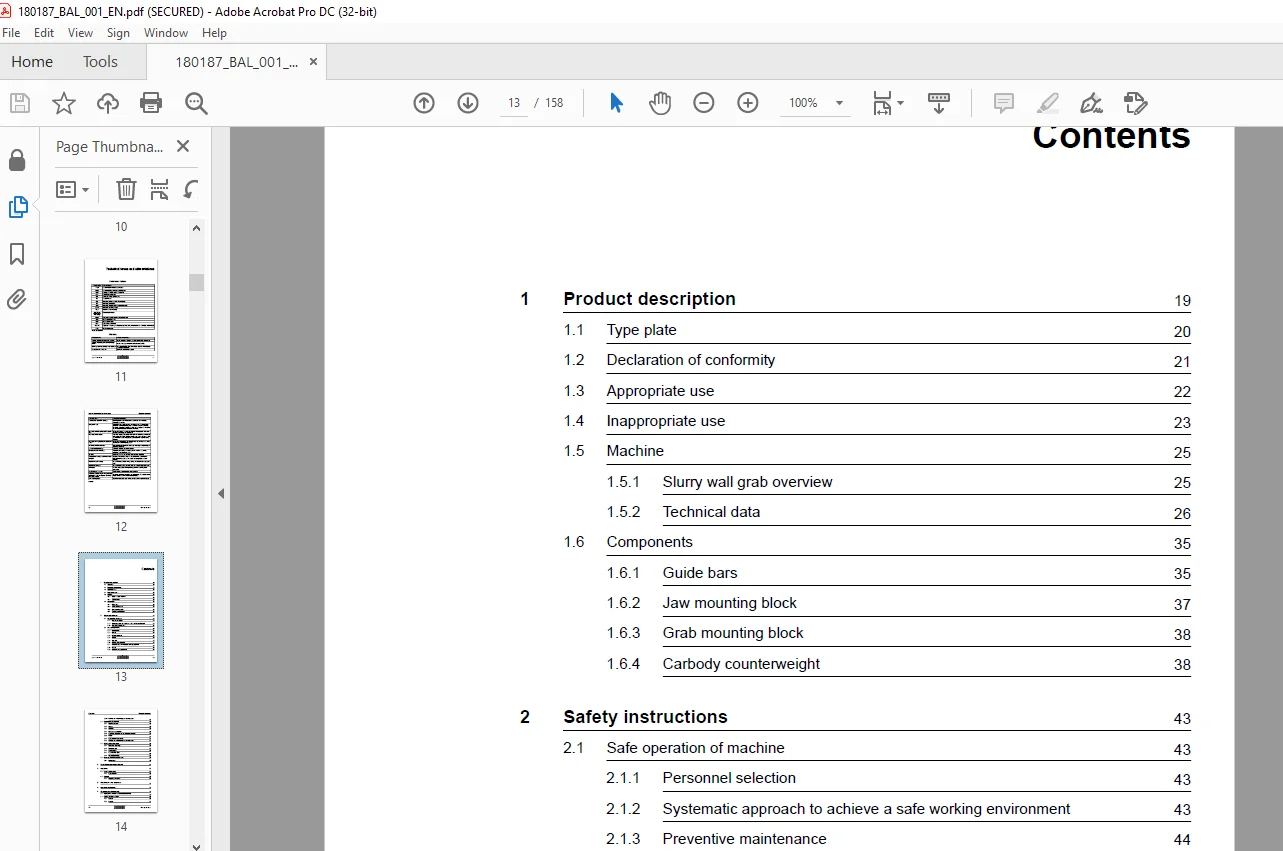
TABLE OF CONTENTS:
Liebherr Crane HSG 5-18 Operator’s Manual SN 180187 – PDF DOWNLOAD
Operator's manual.................................................................................................................................  1
	Foreword......................................................................................................................................  3
	Notes regarding the documentation.............................................................................................................  5
	Technical terms and abbreviations............................................................................................................. 11
	Contents...................................................................................................................................... 13
	1 Product description......................................................................................................................... 19
		1.1 Type plate............................................................................................................................ 20
		1.2 Declaration of conformity............................................................................................................. 21
		1.3 Appropriate use....................................................................................................................... 22
		1.4 Inappropriate use..................................................................................................................... 23
		1.5 Machine............................................................................................................................... 25
			1.5.1 Slurry wall grab overview....................................................................................................... 25
			1.5.2 Technical data.................................................................................................................. 26
		1.6 Components............................................................................................................................ 35
			1.6.1 Guide bars...................................................................................................................... 35
			1.6.2 Jaw mounting block.............................................................................................................. 37
			1.6.3 Grab mounting block............................................................................................................. 38
			1.6.4 Carbody counterweight........................................................................................................... 38
	2 Safety instructions......................................................................................................................... 43
		2.1 Safe operation of machine............................................................................................................. 43
			2.1.1 Personnel selection............................................................................................................. 43
			2.1.2 Systematic approach to achieve a safe working environment....................................................................... 43
			2.1.3 Preventive maintenance.......................................................................................................... 44
		2.2 Areas of responsibility............................................................................................................... 45
			2.2.1 Manufacturer.................................................................................................................... 45
			2.2.2 Owner........................................................................................................................... 45
			2.2.3 Machine operator................................................................................................................ 46
			2.2.4 Slinger......................................................................................................................... 46
			2.2.5 Signaller....................................................................................................................... 47
			2.2.6 Maintenance personnel........................................................................................................... 47
			2.2.7 Installation personnel and disassembly personnel................................................................................ 47
			2.2.8 Helper.......................................................................................................................... 48
			2.2.9 Liebherr service personnel...................................................................................................... 48
			2.2.10 Certified and institutionally authorized persons............................................................................... 48
		2.3 Requirements to personnel............................................................................................................. 49
			2.3.1 Machine operator................................................................................................................ 49
			2.3.2 Slinger......................................................................................................................... 49
			2.3.3 Signaller....................................................................................................................... 50
			2.3.4 Maintenance personnel........................................................................................................... 50
			2.3.5 Installation personnel and disassembly personnel................................................................................ 50
			2.3.6 Helper.......................................................................................................................... 51
			2.3.7 Liebherr service personnel...................................................................................................... 51
			2.3.8 Certified and institutionally authorized persons................................................................................ 51
		2.4 Meaning of the safety signs........................................................................................................... 52
			2.4.1 Mandatory action sign........................................................................................................... 52
			2.4.2 Prohibition sign................................................................................................................ 53
			2.4.3 Warning signs................................................................................................................... 54
			2.4.4 Safe condition signs............................................................................................................ 56
			2.4.5 Fire equipment sign............................................................................................................. 56
		2.5 Meanings of machine-specific signs.................................................................................................... 57
			2.5.1 Notice signs.................................................................................................................... 57
	3 Control and operating elements.............................................................................................................. 61
	4 Operation................................................................................................................................... 65
		4.1 Checks before startup................................................................................................................. 65
			4.1.1 Inspection tour................................................................................................................. 66
		4.2 Disposal.............................................................................................................................. 67
			4.2.1 Disposing of machine............................................................................................................ 67
	5 Operational faults, diagnosis............................................................................................................... 71
	6 Operational planning........................................................................................................................ 75
	7 Assembly and dismantling.................................................................................................................... 79
		7.1 Implementing provision for assembly/disassembly....................................................................................... 79
		7.2 Locking elements overview............................................................................................................. 82
			7.2.1 Split pin....................................................................................................................... 82
			7.2.2 Linchpin........................................................................................................................ 83
			7.2.3 Spring cotter pin............................................................................................................... 84
			7.2.4 Locking spring.................................................................................................................. 85
			7.2.5 Locking washers................................................................................................................. 87
			7.2.6 Self-locking nuts............................................................................................................... 88
		7.3 Installing slurry wall grab on basic machine.......................................................................................... 89
			7.3.1 Converting pulley set for semi-Kelly operation.................................................................................. 89
			7.3.2 Installing hose drum frame on main boom base section............................................................................ 95
			7.3.3 Installing hose drums on hose drum frames....................................................................................... 98
			7.3.4 Installing main boom base section with hose drums on uppercarriage..............................................................105
			7.3.5 Mounting hose guide on main boom section........................................................................................107
			7.3.6 Mounting support feet on main boom section......................................................................................108
			7.3.7 Mounting hose guide on main boom head...........................................................................................109
			7.3.8 Assembling main boom............................................................................................................111
			7.3.9 Mounting semi-Kelly mount on main boom head.....................................................................................111
			7.3.10 Installing slurry wall grab on machine.........................................................................................113
	8 Transport...................................................................................................................................123
		8.1 Loading machine.......................................................................................................................123
		8.2 Transporting machine..................................................................................................................125
			8.2.1 Transporting slurry wall grab...................................................................................................125
			8.2.2 Transporting main boom base section.............................................................................................126
			8.2.3 Transporting main boom components...............................................................................................130
	9 Maintenance.................................................................................................................................133
		9.1 Maintenance and inspection schedule...................................................................................................133
		9.2 Lubricants and consumables............................................................................................................136
			9.2.1 Filling capacity table..........................................................................................................136
			9.2.2 Lubrication diagram.............................................................................................................137
			9.2.3 Hydraulic oil...................................................................................................................140
			9.2.4 Preservation medium (anti-corrosion coating)....................................................................................141
		9.3 Hydraulic rotating device.............................................................................................................144
			9.3.1 Lubricating slewing ring........................................................................................................144
			9.3.2 Checking slewing head for leak tightness........................................................................................145
		9.4 Slurry wall grab......................................................................................................................146
			9.4.1 Cleaning slurry wall grab.......................................................................................................146
			9.4.2 Lubricating all movable parts via grease nipples................................................................................146
			9.4.3 Checking grab jaws push rods, scraper, guide bars, grab teeth and bucket adapters for damage and wear...........................147
			9.4.4 Rinsing hydraulic lines in slurry wall grab.....................................................................................147
			9.4.5 Hydraulic cylinders and hydraulic lines.........................................................................................149
			9.4.6 Checking pins for tight fit, damage and wear; checking locking element and bushings for presence, tight fit, damage and wear....151
			9.4.7 Checking electrical components for function.....................................................................................151
			9.4.8 Changing battery of slurry wall grab............................................................................................152
			9.4.9 Replacing hydraulic oil filter..................................................................................................154
		9.5 Hose drums............................................................................................................................155
			9.5.1 Cleaning hose drums and hose guides.............................................................................................155
			9.5.2 Exchanging hydraulic oil filter.................................................................................................155
			9.5.3 Changing gearbox oil of hose drums..............................................................................................156
	Index.........................................................................................................................................157
Customer Support: [email protected]
PLEASE NOTE:
- This is the SAME MANUAL used by the dealerships to diagnose your vehicle
- No waiting for couriers / posts as this is a PDF manual and you can download it within 2 minutes time once you make the payment.
- Your payment is all safe and the delivery of the manual is INSTANT – You will be taken to the DOWNLOAD PAGE.
- So have no hesitations whatsoever and write to us about any queries you may have : heydownloadss @gmail.com
S.V