
Liebherr Crane LR 1750 SL Load Chart Manual 074734 – PDF DOWNLOAD
$28.95
Liebherr Crane LR 1750 SL Load Chart Manual 074734 – PDF DOWNLOAD
Description
Liebherr Crane LR 1750 SL Load Chart Manual 074734 – PDF DOWNLOAD
FILE DETAILS:
Liebherr Crane LR 1750 SL Load Chart Manual 074734 – PDF DOWNLOAD
Language : English
Pages : 357
Downloadable : Yes
File Type : PDF
IMAGES PREVIEW OF THE MANUAL:
DESCRIPTION:
Liebherr Crane LR 1750 SL Load Chart Manual 074734 – PDF DOWNLOAD
Explanations:
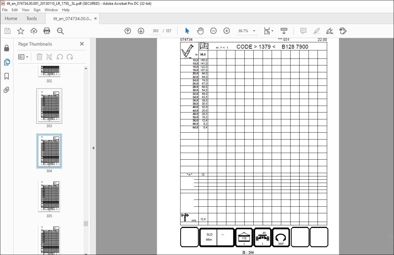
1.1 The load capacity values in the load capacity tables are indicated in tons [t].
1.2 The working radius is the horizontal distance indicated in meters [m] between the centre of gravity of the load centre of gravity from the slewing axis of the crane’s superstructure as measured from the ground. This also applies when the crane is subjected to loads; i.e., this includes boom flexure.
1.3 Boom positions other than those specified in the load capacity tables are prohibited.
1.4 The boom must only be moved in those ranges for which load capacity values are given, even without a load, as otherwise the crane can topple. In normal operations, this is prevented by the overload safety device. When “Assembly” is engaged (with the assembly key-operated switch) the boom must only be luffed or lowered within the specified working radius ranges.
1.5 The given load capacities include the weight of the slinging tackle, hoisting and take-up tackle. The possible weight of the load to be hoisted is thus less than the weights above.
TABLE OF CONTENTS:
Liebherr Crane LR 1750 SL Load Chart Manual 074734 – PDF DOWNLOAD
1 Explanations page I – 6
2 There is a danger of tipping or a risk of the load-bearing
structural members becoming overloaded if: page I – 7
3 Utilisation of the crane (load collective) page I – 8
4 LICCON-overload safety device and limit switch page I – 9
5 Rope winches (hoisting gears) page I – 9
6 Hoist rope reeving page I – 10
7 Hook block and load hook page I – 11
7 1 Loading hooks and hook blocks for crane operation
with 1 hoisting rope winch during single operation page I – 12
7 1 1 Load hook 16 E
(0 rope pulleys / 16 0 t load) page I – 12
7 1 2 Hook block 50 EM
(1 rope pulleys / 47 5 t load) page I – 12
7 1 3 Hook block 125 EM
(3 rope pulleys / 107 5 t load) page I – 13
7 1 4 Hook block 200 DM
(5 rope pulleys / 164 0 t load) page I – 13
7 1 5 Double hook block 400 – 200 DMZ
(7 rope pulleys / 200 0 t load) page I – 14
7 1 6 Double hook block 600 – 300 DMZ
(11 rope pulleys / 300 0 t load) page I – 15
7 2 Hook blocks for crane operation with 2 hoisting rope
winches during parallel operation page I – 16
7 2 1 Double hook block 400 – 200 DMZ
(2 x 7 rope pulleys / 400 0 t load) page I – 16
7 2 2 Double hook block 600 – 300 DMZ
(2 x 11 rope pulleys / 600 0 t load) page I – 17
Load capacity table book LR 1750
blr1750 ao I – 2 /94
Contents
8 Minimum hoist rope reevings and minimum hook block weights page I – 18
8 1 Minimum hoist rope reevings and minimum hook block
weights, necessary for certain operating modes due to
static reasons page I – 19
8 1 1 Hoisting rope reeving SDWV-operation;
SDWVB-operation; SDWVBW-operation
TAB 12800056 page I – 19
8 1 2 Hoisting rope reeving SDWVBW_15°-operation page I – 21
8 1 3 Hoisting rope reeving SL9D2F-operation;
SL9D2FB-operation
TAB 15400039 page I – 22
8 1 4 Hoisting rope reeving SLK-operation
TAB 15400034 page I – 23
8 1 5 Hoisting rope reeving SLK-operation
TAB 12800169 page I – 24
8 1 6 Hoisting rope reeving SL9D2F-operation;
SL9D2FB-operation
TAB 15400065 page I – 25
8 1 7 Hoisting rope reeving SDWV-operation;
SDWVB-operation; SDWVBW-operation
TAB 15400072 page I – 26
8 1 8 Hoisting rope reeving S6D2W-operation;
S6D2WB-operation
TAB 15400101 page I – 28
8 1 9 Hoisting rope reeving S6D2WV-operation;
S6D2WVB-operation
TAB 15400105 page I – 31
8 2 Necessary minimum hoist rope reevings for a reliable
weighing of the load for LICCON overload protection page I – 33
8 3 Necessary minimum hoist rope reevings during
parallel operation page I – 34
9 Procedure for ascertaining the necessary hoist rope reeving
and hook block page I – 35
9 1 Stage 1: Ascertaining the load page I – 35
9 2 Stage 2: Ascertaining the minimum hoist rope reeving in
correlation with the maximum permissible cable pull
(nmin [reeving chart]) page I – 36
9 3 Stage 3: Ascertaining the minimum hoist rope reeving
and the minimum hook block weight for static
reasons (nmin [static]), (Gmin [static]) page I – 37
9 4 Stage 4: Ascertaining the minimum hoist rope reeving for
a reliable weighing of the load for LICCON overload
protection (nmin [weighing of the load]) page I – 37
9 5 Stage 5: Ascertaining the minimum hoist rope reeving for
a functioning parallel operation control
(nmin [parallel operation]) page I – 38
9 6 Stage 6: Ascertaining the minimum hoist rope reeving
(nmin) and the minimum hook block weight (Gmin) which
must be applied for lifting of the load page I – 38
Load capacity table book LR 1750
blr1750 ao I – 3 /94
Contents
10 Load capacity reductions page I – 39
10 1Load capacity reduction with mounted boom nose page I – 39
10 2Load capacity reduction with overlying tie bars page I – 39
11 Boom system page I – 40
11 1Abbreviations for the assemblies of the boom system page I – 40
11 1 1 Main boom page I – 40
11 1 2 Fixed accessories page I – 40
11 1 3 Moving accessories page I – 40
11 1 4 Derrick boom page I – 40
11 1 5 Derrick counterweight page I – 41
11 2Combination of the assemblies to operating modes page I – 41
12 Explanation of symbols page I – 42
Hoisting rope reeving page I – 42
Load capacity in metric tons page I – 42
Operating modes symbol page I – 42
Crane operation without accessories page I – 43
Crane operation with accessories page I – 44
Crane operation with main boom with mounted accessories page I – 47
Operating modes with several hook blocks page I – 48
Hook block weight on the main boom during crane
operation on the additional boom page I – 49
Hook block weight on the additional boom during crane
operation on the main boom page I – 50
Special operating modes page I – 51
Pontoon-based crane operation page I – 51
Limitation descriptions for operating modes page I – 55
Characteristics: 1) page I – 55
Characteristics: 2) page I – 55
Characteristics: 3) page I – 56
Characteristics: 4) page I – 56
Characteristics: 5) page I – 57
Characteristics: 6) page I – 58
Characteristics: 7) page I – 58
Characteristics: 8) page I – 59
Characteristics: 9) page I – 59
Characteristics: 10) page I – 60
Characteristics: 11) page I – 61
Characteristics: 12) page I – 61
Characteristics: 13) page I – 62
Characteristics: 14) page I – 62
Characteristics: 15) page I – 63
Load capacity table book LR 1750
blr1750 ao I – 4 /94
Contents
Characteristics: 16) page I – 64
Characteristics: 17) page I – 64
Characteristics: 18) page I – 65
Characteristics: 19) page I – 66
Characteristics: 20) page I – 67
Characteristics: 21) page I – 68
Characteristics: 22) page I – 68
Characteristics: 23) page I – 69
Characteristics: a) page I – 70
Characteristics: * ) page I – 71
Characteristics: spec ) page I – 71
Characteristics: SP page I – 72
Characteristics: n=60 page I – 72
Working radius symbols page I – 73
Lattice main boom length page I – 74
Short code page I – 74
Hoisting rope reeving page I – 74
Main Boom Angle page I – 74
Derrick counterweight distance page I – 75
Permissible wind speed page I – 75
Counterweight page I – 75
Central counterweight page I – 75
Centre counterweight and support page I – 76
Derrick counterweight distance page I – 76
Slewing range page I – 77
13 Permissible turning speed and side inclination page I – 78
13 1Maximum permissible turning speed of the crane’s
superstructure with suspended nominal load page I – 78
13 2Maximum possible side inclination of the crane when
working with the load capacity tables page I – 78
14 Wind influences during crane operation page I – 79
14 1Definition of terms page I – 79
14 2Wind influence on the LICCON-overload safety device page I – 81
14 2 1 Wind from the rear page I – 81
14 2 2 Wind from the front page I – 81
14 2 3 Wind from the side page I – 81
Load capacity table book LR 1750
blr1750 ao I – 5 /94
Contents
14 3Permissible wind speed and surface susceptibility to wind page I – 82
14 3 1 Establishing the maximum permissible wind speed page I – 84
14 3 2 Calculating the maximum permissible wind speed
using a formula page I – 84
14 3 3 Establishing the maximum permissible wind
speed by way of wind force diagrams page I – 86
14 3 4 Wind force diagrams page I – 88
Customer Support: [email protected]
https://vimeo.com/892177925?share=copy
S.V