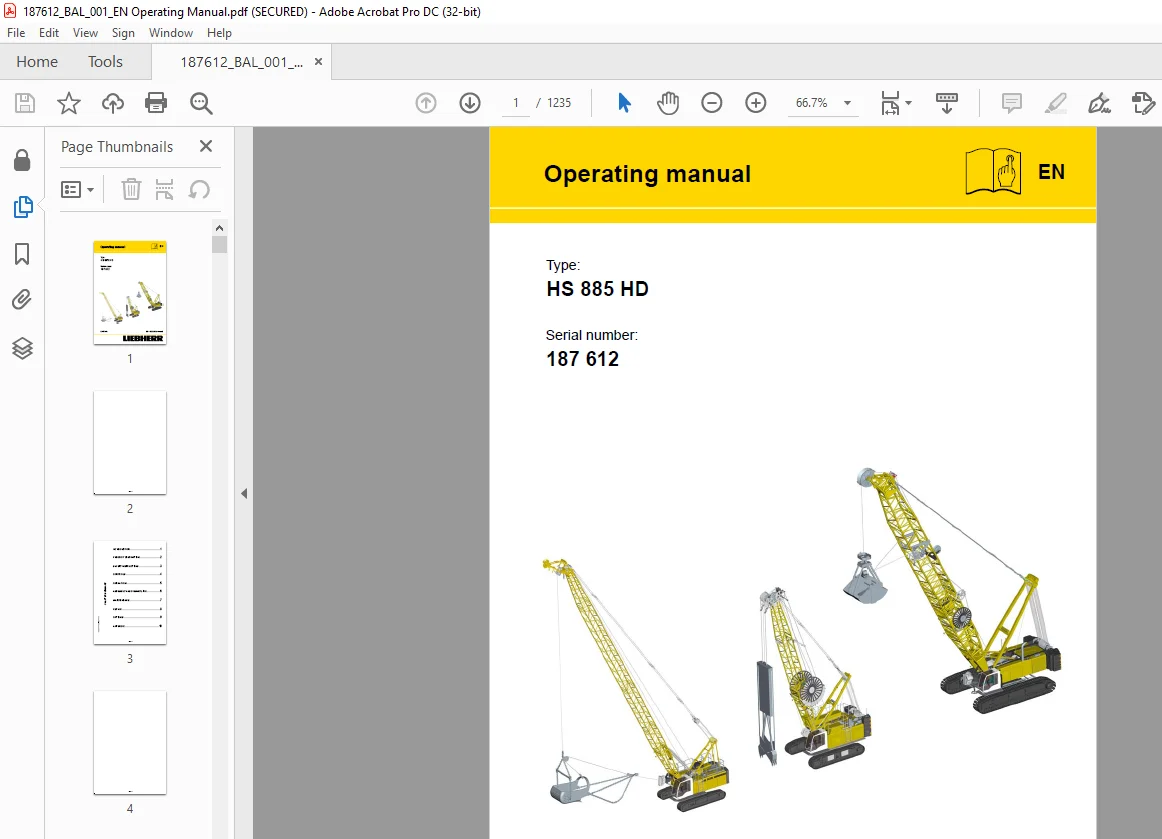
Liebherr Crawler Crane HS 885 HD Operating Manual SN 187612 – PDF DOWNLOAD
$36.95
Liebherr Crawler Crane HS 885 HD Operating Manual SN 187612 – PDF DOWNLOAD
Description
Liebherr Crawler Crane HS 885 HD Operating Manual SN 187612 – PDF DOWNLOAD
FILE DETAILS:
Liebherr Crawler Crane HS 885 HD Operating Manual SN 187612 – PDF DOWNLOAD
Language : English
Pages : 1235
Downloadable : Yes
File Type : PDF
DESCRIPTION:
Liebherr Crawler Crane HS 885 HD Operating Manual SN 187612 – PDF DOWNLOAD
INTRODUCTION
1.1 Foreword
The Liebherr name not only stands for products and services. It has become well known for ideas and innovations. For progress, which has proven itself in the market. We continuously expand and improve our wide variety of product and service offering with great intensity. To do so, the constant cooperation and the experience exchange with our customers and business partners all over the world is a prerequisite. For that reason we are thankfull for every suggestion and recommendation for improvement.
PRODUCT DESCRIPTION
2.1 General
This chapter
– provides information about the machine deployment options and provides warnings about
incorrect or improper use,
– describes the structure of the machine, along with its main components,
– cites important technical data.
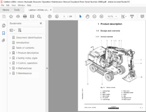
The illustrations in the Product Description chapter are for general information about the product and
do not necessarily reflect the current status of equipment and fittings on the machine.
Figures in brackets, for example (7), refer to the relevant item number in the illustration in question.
Where directions are stated – forwards/back, left/right – these always relate to the driver’s seated
position in the driver’s cab
IMAGES PREVIEW OF THE MANUAL:
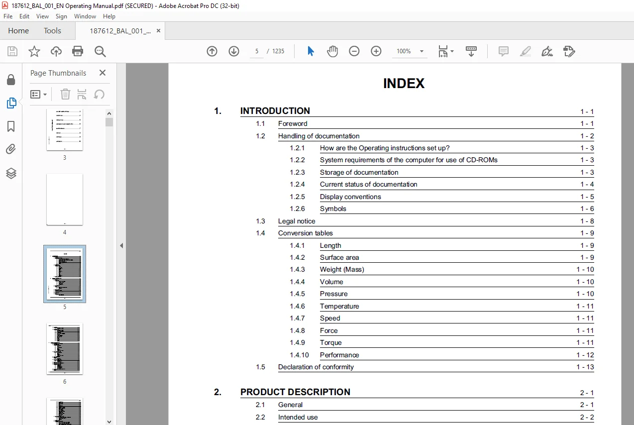
TABLE OF CONTENTS:
Liebherr Crawler Crane HS 885 HD Operating Manual SN 187612 – PDF DOWNLOAD
1 INTRODUCTION 29
1 1 Foreword 29
1 2 Handling of documentation 30
1 2 1 How are the Operating instructions set up? 31
1 2 2 System requirements of the computer for use of CD-ROMs 31
1 2 3 Storage of documentation 31
1 2 4 Current status of documentation 32
1 2 5 Display conventions 33
1 2 6 Symbols 34
1 3 Legal notice 36
1 4 Conversion tables 37
1 4 1 Length 37
1 4 2 Surface area 37
1 4 3 Weight (Mass) 38
1 4 4 Volume 38
1 4 5 Pressure 38
1 4 6 Temperature 39
1 4 7 Speed 39
1 4 8 Force 39
1 4 9 Torque 39
1 4 10 Performance 40
1 5 Declaration of conformity 41
2 PRODUCT DESCRIPTION 47
2 1 General 47
2 2 Intended use 48
2 2 1 State-of-the-art technology 49
2 2 2 Machine classification 49
2 2 3 Appropriate use 51
2 2 4 Inappropriate use 53
2 3 Machine overview 55
2 4 Boom 56
2 4 1 Information on boom designations 56
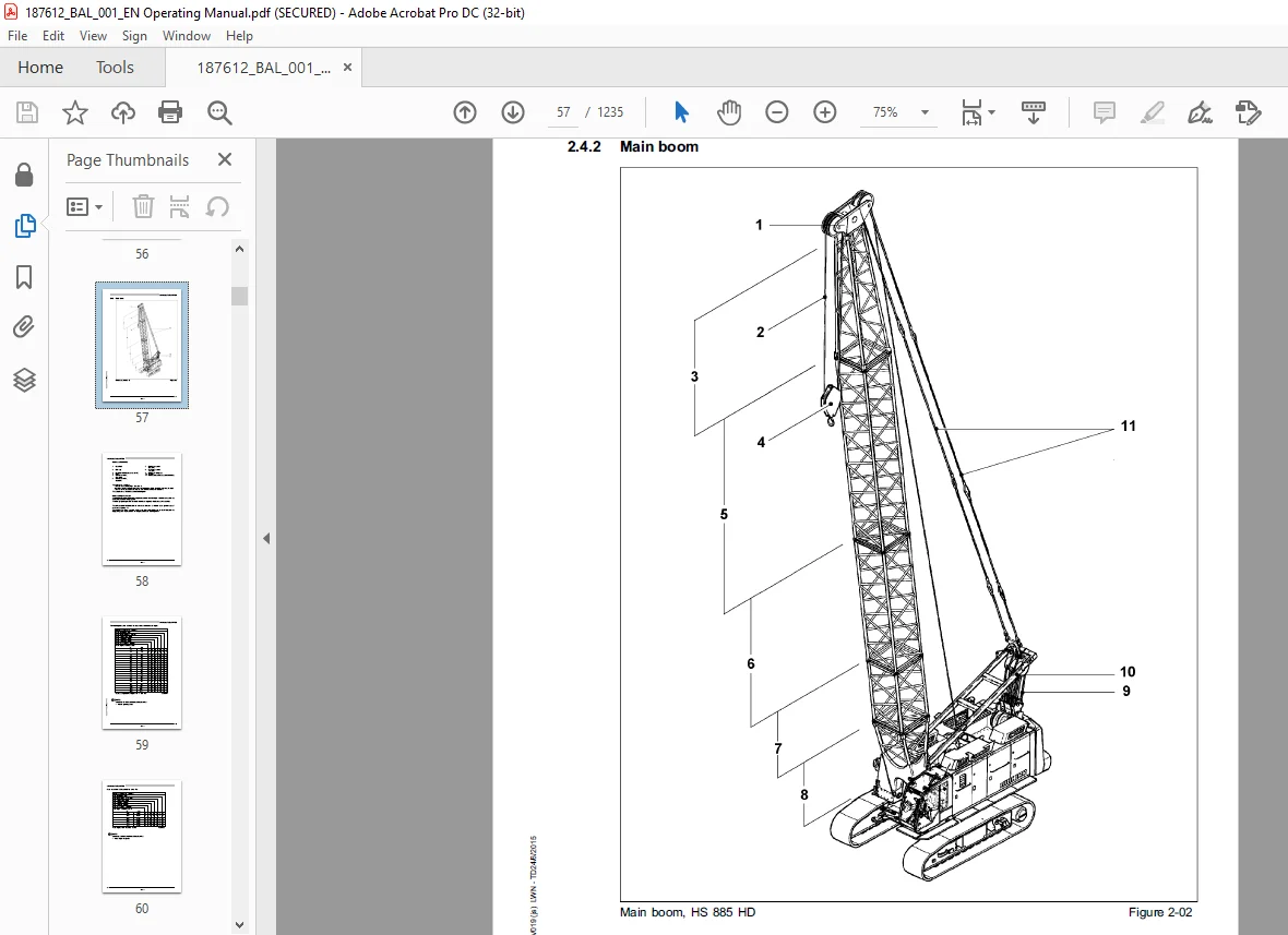
2 4 2 Main boom 57
2 5 Superstructure 74
2 6 Central power unit (MAN) 76
2 7 Central power unit (LIEBHERR) 78
2 8 Undercarriage 80
2 9 Undercarriage 82
2 10 Ballast 84
2 10 1 Rear counterweight 84
2 11 Technical data 85
2 11 1 Dimensions and weights 87
2 12 Technical data US 94
2 12 1 Dimensions and weights 94
2 12 2 Conditions of use (MAN) 101
2 12 3 Emissions 102
2 12 4 Engine (MAN) 102
2 12 5 Conditions of use (LIEBHERR) 103
2 12 6 Emissions 103
2 12 7 Engine (LIEBHERR) 104
2 12 8 Hydraulic system 105
2 12 9 Winches 106
2 12 10 Swing 107
2 12 11 Crawlers 107
2 12 12 Control 108
3 SAFETY INSTRUCTIONS 115
3 1 Technical condition of the machine 115
3 2 Areas of responsibility 116
3 2 1 Manufacturer 116
3 2 2 Owner 116
3 2 3 Machine operator 116
3 2 4 Rigger 116
3 2 5 Signalman 117
3 2 6 Maintenance personnel 117
3 3 Requirements of personnel 118
3 3 1 Machine operator 118
3 3 2 Rigger 118
3 3 3 Signalman 118
3 3 4 Maintenance personnel 119
3 4 Personal protective gear 120
3 5 Work area 121
3 5 1 Danger zone 122
3 6 Safety and monitoring devices 123
3 6 1 Safety devices 123
3 6 2 Monitoring devices 125
3 7 Safety signs on the machine 127
3 8 Safety signs on the machine (US market) 130
3 9 Meaning of the safety signs 133
3 9 1 Prohibition signs 133
3 9 2 Warning signs 133
3 9 3 Fire protection signs 135
3 9 4 Mandatory signs 135
3 10 Meaning of the machine-specific safety signs 137
3 11 Hazards 139
3 11 1 Mechanical action 139
3 11 2 Electrical energy 140
3 11 3 Hydraulic energy 141
3 11 4 Burns 142
3 11 5 Chemical burns 143
3 11 6 Fire and explosion 144
3 11 7 Poisoning and suffocation 145
3 11 8 Electromagnetic influence 146
3 11 9 Exposure to wind 147
3 11 10 Snow and ice loads 151
3 11 11 Ground bearing strength 151
3 11 12 Lightning strikes 152
3 11 13 Overhead power lines 153
3 11 14 Excavation work 156
3 11 15 Environment 158
3 12 What to do in dangerous situations 159
3 12 1 How to respond in the event of a current transfer 159
3 12 2 Procedure in the event of fire 161
3 12 3 Firefighting 161
3 13 Working at heights 165
3 14 Application on floating devices 167
3 14 1 Operation of the machine on floating devices DANGER ! 168
3 14 2 Transport of the machine on floating devices 169
3 14 3 Higher risk of machine corrosion on floating devices 169
3 15 Use at low temperatures 170
3 15 1 Operation of the machine down to -20 °C (-4 °F) (standard 171
3 15 2 Operation of the machine down to -25 °C (-13 °F) 171
3 15 3 Operation of the machine down to -40 °C (-40 °F) 171
3 16 Hand signals 172
3 16 1 General hand signals in accordance with BGV A8 173
3 16 2 Special hand signals for attachment operations 175
3 16 3 Hand signals for lifting operations in accordance with AS 178
4 CONTROLS 187
4 1 General 187
4 2 Operational controls on the undercarriage 188
4 3 Operational controls on the superstructure 189
4 4 Operator’s cab 190
4 4 1 Operator’s cab overview 190
4 4 2 Control stand overview 192
4 4 3 Overview of control stand from above 194
4 5 Overview of the LCD screen 197
4 5 1 Main areas of the screen 197
4 5 2 Description of the main areas of the screen 197
4 5 3 Sequence of mode screens 199
4 6 Left-hand control panel (X12) 201
4 7 Left-hand control panel (X11) 203
4 8 Litronic service panel on the LCD screen 205
4 8 1 Menu bar 205
4 8 2 Keyboard menu 206
4 9 Right-hand control panel (X23) 208
4 10 Right-hand control panel (X23) (optional) 213
4 10 1 Emergency shut-down switch 219
4 10 2 Joysticks, pedals, handwheels 220
4 11 Operating the machine – auxiliary functions 222
4 11 1 Adjusting the controls 222
4 11 2 Driver’s seat 223
4 11 3 LCD screen adjustments 224
4 11 4 Windshield wiper 224
4 11 5 Interior lighting in the superstructure 226
4 11 6 Cab lighting 226
4 11 7 Radio 226
4 11 8 Hooter 226
4 11 9 Cigarette lighter 226
4 11 10 Cab adjustment cylinder * 227
4 11 11 Cab height adjustment * 227
4 12 Operator guidance on the display screen 229
4 13 Start-up screen 229
4 14 Set-up screens 230
4 14 1 Set-up screen 1 for main boom 231
4 14 2 Set-up screen 3 for main boom with fixed fly jib 237
4 14 3 Example of a load capacity chart for load moment limitati 239
4 15 “Mode screen” page 241
4 16 “Operating modes” screen 248
4 17 “Power unit monitoring” screen 250
4 18 Motor error message 253
4 18 1 Serious motor error message 253
4 18 2 General motor error message 254
4 19 “Fault monitor” screen 255
5 OPERATION 263
5 1 General 263
5 1 1 Safe working with the machine 263
5 2 Checks before daily operation 264
5 2 1 Tour of inspection 264
5 2 2 Checks 264
5 3 Daily start up 266
5 3 1 Battery main switch 266
5 3 2 Switching on the ignition 266
5 3 3 Confirming the existing set-up 266
5 3 4 Checking the fuel level 269
5 3 5 Refueling the machine 269
5 3 6 Select operating mode 270
5 3 7 Select operating mode on the left hand con- trol desk (X12 271
5 3 8 Select an operating mode in the “Operating modes” screen 275
5 4 Starting the diesel engine 278
5 4 1 Prerequisites 278
5 4 2 Adjusting the engine speed 280
5 4 3 Lowering the safety lever (access lever) 281
5 5 Machine operation – main functions 282
5 5 1 Checks/activities on start-up 283
5 5 2 Adjusting the main boom 285
5 5 3 Using the electronic load moment limiter (LML) 286
5 5 4 Load pick-up equipment 288
5 5 5 Resetting the load capacity display to zero (taring) 288
5 6 Operating the hoisting winches 289
5 7 Lifting mode 293
5 7 1 Operating the hoisting winches 293
5 7 2 Lifting loads with the main boom head using runner attachm 296
5 7 3 Lifting loads with the tip boom (runner) 297
5 7 4 Lifting loads with the main boom head with fixed fly jib f 298
5 7 5 Lifting loads with the tip boom mounted on the main boom h 300
5 7 6 Lifting loads with the main boom head, with tip boom fitte 301
5 7 7 Lifting loads with the main boom head with fixed fly jib f 302
5 7 8 Twin hook operation 304
5 7 9 Combined two-hook operation with fixed fly jib 311
5 8 Winches overdrive 315
5 8 1 General 315
5 8 2 Preselection 315
5 8 3 Switching conditions 317
5 8 4 Safety functions 317
5 8 5 Briefly changing to heavy duty mode 318
5 8 6 Activating the slewing gear 319
5 8 7 Slewing gear free-wheel 322
5 9 A-frame position 324
5 9 1 Travelling with the machine 326
5 9 2 Travel gear overdrive 329
5 9 3 Adjust cylinder 331
5 9 4 Free-fall operation 333
5 9 5 Working in free-fall operation 341
5 9 6 Shutting down free-fall operation 342
5 9 7 Winch standstill monitoring 342
5 9 8 Lowering control (SWG control unit) 343
5 9 9 Interlock control 345
5 9 10 Winch synchronization (optional) 347
5 9 11 Grab control 348
5 9 12 Ramming control/chisel control 349
5 9 13 Casing oscillator 357
5 10 Litronic ® test system 360
5 10 1 Properties 360
5 10 2 General 360
5 10 3 Starting the Litronic ® test system 361
5 10 4 The menus 362
5 10 5 Main menu 362
5 10 6 INPUT/OUTPUT menu 363
5 10 7 MEMORY menu 363
5 10 8 SELECT menu 364
5 10 9 CORRECTION menu 367
5 10 10 MESSAGES menu 368
5 10 11 SPECIAL FUNCTIONS menu 369
5 11 Operating the machine – auxiliary func- tions 374
5 11 1 Adjusting the driver’s seat 374
5 11 2 LCD screen adjustments 375
5 11 3 Windshield wiper 376
5 11 4 Windshield wiper 377
5 11 5 Lighting 379
5 11 6 Radio 380
5 11 7 Hooter 380
5 11 8 Ashtray 381
5 11 9 Cigarette lighter and socket in the cab 381
5 12 Shutting down the machine 382
5 12 1 Laying down the boom 383
5 12 2 Shutting down the diesel engine 384
5 12 3 Park position of the ignition starter switch 384
5 12 4 Checks before leaving the machine 385
5 13 Emergency operation control 386
5 13 1 Functions of the control desk 387
5 13 2 Using the emergency operation controller 388
6 ASSEMBLY AND DISASSEMBLY 395
6 1 General 395
6 2 Assembly, dismantling and reconfiguring 397
6 3 Operational planning 398
6 3 1 Defining the working range 398
6 3 2 Defining the setup 411
6 3 3 Assembling and preparing the equipment for transport 411
6 3 4 Required hoisting rope length 413
6 4 Safety precautions for assembly, dismantling and reconfiguri 415
6 4 1 Requirements for the erecting team 415
6 4 2 Requirements for the site 415
6 4 3 Rules for executing the work 416
6 4 4 Lifting the crawler carriers and basic machine from the tr 417
6 4 5 Adjusting the crawler carriers via cylinders 418
6 5 Unloading the basic machine 419
6 5 1 Prerequisites 419
6 5 2 Unloading the basic machine without tilting-back supports 420
6 5 3 Unloading the basic machine with tilting-back supports on 422
6 5 4 Unloading the basic machine without crawler side frames us 424
6 5 5 Unloading the basic machine and crawler side frames using 428
6 5 6 Preparing for assembly mode 429
6 5 7 Starting assembly mode 433
6 5 8 Preparing the mounting crane 436
6 5 9 Erecting the A-frame 437
6 5 10 Drive the machine off the low-loader 439
6 5 11 Removing the superstructure locking 440
6 5 12 Adjust crawler carrier on work track 441
6 5 13 Unloading the basic machine using the self-loading system 445
6 5 14 Basic machine used as an erection crane 454
6 5 15 Secure the components for installation work 455
6 5 16 Rope reeving diagram 457
6 5 17 Controlling the tilting-back supports (Fig- ure 58) 459
6 5 18 Controlling the auxiliary winch 460
6 5 19 Attaching the crawler carrier 461
6 5 20 Mounting the crawler carrier under difficult conditions 476
6 5 21 Retract the support cylinders 481
6 5 22 Unloading the basic machine and crawler side frame using 485
6 5 23 Transporting the superstructure 487
6 5 24 Turning the telescopic outriggers on the ba- sic machine 488
6 5 25 Lifting the basic machine from the transport vehicle 491
6 5 26 Supporting the opposite telescopic outrigger 491
6 5 27 Unloading the second crawler carrier 492
6 5 28 Pushing the crawler carrier onto the chord 493
6 5 29 Supply to the travel gear drive units 497
6 5 30 Attaching steps and ladders 498
6 5 31 Platforms on the superstructure 498
6 5 32 Unloading the rear counterweight 499
6 5 33 Location of the rope pulleys on the rear counterweight 502
6 5 34 General 503
6 5 35 Mounting the rear counterweight (Fig- ure 123) 504
6 6 Assembling the main boom 508
6 6 1 Prerequisites 508
6 6 2 Overview of assembly stages 508
6 6 3 Unloading and positioning the boom head 509
6 6 4 Assembling the main boom 509
6 6 5 Assembling the main boom 510
6 6 6 Attaching the main boom to the pivot piece 515
6 6 7 Luffing the hoisting rope 519
6 6 8 Rope reeving plans 520
6 7 Reeve the cable 522
6 7 1 Connecting the electrics 524
6 8 Hoisting limit switch 527
6 8 1 Snap hook on hoisting limit switch weight (wedge) 529
6 8 2 Erecting the main boom 531
6 8 3 Erecting procedure 533
6 8 4 Cancelling mounting mode 534
6 9 Dismantling the main boom 535
6 9 1 Prerequisites 535
6 9 2 Overview of dismantling stages 535
6 9 3 Preparations in lifting operation 536
6 9 4 Select assembly mode 536
6 9 5 Lay down the main boom 537
6 9 6 Laying down procedure 539
6 9 7 Disconnecting the electrics 540
6 9 8 Pulling out the hoisting ropes 542
6 9 9 Detaching the main boom from the pivot piece 543
6 9 10 Dismantling the main boom 547
6 10 Dismantling the basic machine 548
6 10 1 Prerequisites 548
6 10 2 Overview of disassembly / uppercarriage with and without 549
6 10 3 Overview of disassembly using the self-loading system 550
6 10 4 Overview of disassembly using the assist crane 552
6 10 5 Setting down the rear counterweight 553
6 10 6 Loading the rear counterweight 556
6 10 7 Adjusting crawler carrier on transport track 559
6 10 8 Basic machine used as an erection crane 563
6 10 9 Secure the components for dismantling 565
6 10 10 Rope reeving plan 567
6 10 11 Controlling the tilting-back supports (Fig- ure 188) 569
6 10 12 Controlling the auxiliary winch 570
6 10 13 Preparing to dismantle the crawler carriers 571
6 10 14 Supporting the basic machine 573
6 10 15 Removing the crawler carrier from the undercarriage 581
6 10 16 Removing the crawler carrier under difficult conditions 588
6 10 17 Loading the basic machine 595
6 10 18 Setting down the A-frame 597
6 10 19 Setting down the A-frame 599
6 10 20 Attachment points 601
6 10 21 Fixing mounting chains on the superstructure and support 601
6 10 22 Loosening the wedges on the telescopic out- riggers 602
6 10 23 Disconnecting the hydraulic supply 602
6 10 24 Pushing the crawler carrier off the chord 603
6 10 25 Remove mounting chains from the super- structure 607
6 10 26 Transporting the basic machine 609
6 10 27 Turning the telescopic outriggers on the ba- sic machine 609
6 10 28 Platforms on the superstructure 612
6 10 29 Remove steps and ladders 612
6 10 30 Fitting the superstructure locking 613
6 10 31 Drive the machine onto the low-loader 615
6 10 32 Setting down the A-frame 617
6 10 33 Taking the basic machine out of operation 619
6 11 Transport 620
6 11 1 Safety precautions for loading and unloading 620
6 11 2 Transporting the basic machine with a low-loader 621
6 11 3 Transporting the basic machine with a low-loader 623
6 11 4 Transporting attachments 625
6 11 5 Loading the basic machine with an auxiliary crane 627
6 11 6 Transporting overseas 629
7 MAINTENANCE 635
7 1 General 635
7 1 1 Lubricants 636
7 1 2 Welding work 636
7 1 3 Cylinder 636
7 2 Maintenance chart 637
7 2 1 Work to be carried out 637
7 3 Diesel engine 653
7 3 1 Engine; check oil level and oil pressure 653
7 4 Fuel system (MAN engine) 655
7 4 1 Check the water separator on the fuel prefilter, drain off 656
7 4 2 Draining condensate from the fuel filter 658
7 4 3 Draining condensate from the fuel tank 660
7 4 4 Cleaning the fuel prefilter 662
7 4 5 Replacing the fuel filter 664
7 4 6 Bleeding the fuel system 666
7 5 Cooling system 668
7 5 1 Check coolant level, top up if necessary 668
7 6 The dry air filter (MAN / Liebherr) 669
7 6 1 Arrangement on the central power unit 669
7 6 2 Emptying the dust collection container 669
7 7 Power divider 670
7 7 1 General 670
7 7 2 Checking the gearbox oil level 670
7 7 3 Draining the gearbox oil 671
7 7 4 Refilling the gearbox oil 671
7 7 5 Recommendation for servicing 671
7 7 6 Gearbox oil cooler 671
7 8 Crawlers 672
7 8 1 Cleaning and maintaining the crawlers 672
7 9 Guide wheels 673
7 9 1 Overview of the crawler tensioning systems 673
7 10 Checking the chain tension 675
7 10 1 Tensioning the chain with grease tensioner 675
7 10 2 Floor plates 676
7 11 Hydraulic system 679
7 11 1 Check the hydraulic system for leaks 679
7 12 Hydraulic oil tank 680
7 12 1 Checking the level in the hydraulic oil tank using the si 680
7 12 2 Filling with hydraulic oil 681
7 12 3 Draining the hydraulic oil 682
7 12 4 Cleaning the magnetic rod in the return filter 683
7 13 Hydraulic filter 685
7 13 1 Changing the pressure filter 685
7 14 Slewing gear transmission/Rotary connection 687
7 14 1 Slewing gear transmission, checking the oil level 687
7 14 2 Lubricating the crown gear/pinion 687
7 14 3 Lubricating the slew ring bearing races 687
7 15 Winches 689
7 15 1 Checking the oil level of winches 1 and 2 and boom winch 689
7 15 2 Safety harness attachment point on upper- carriage 689
7 15 3 Lubrication points on the boom winch 690
7 15 4 Needle bearing 690
7 15 5 Counter bearing 690
7 15 6 Torque support 690
7 15 7 Balancing rocker 690
7 15 8 Boom winch and A-frame; rope pulleys 690
7 16 Ropes and pulleys 691
7 16 1 Checking the rope against end of service life criteria 691
7 16 2 Check the rope for diameter shrinkage 692
7 16 3 Check for rope deformations 693
7 16 4 Check ropes for corrosion 694
7 16 5 Check ropes for abrasion 695
7 16 6 Check ropes for the effects of heat 695
7 16 7 Check the rope for number of permitted wire breaks 697
7 16 8 Selecting a rope 700
7 16 9 Storing ropes 704
7 16 10 Transporting ropes 705
7 16 11 Checking the rope drive 705
7 16 12 Winding ropes 710
7 16 13 Luffing ropes 712
7 16 14 Lubricating ropes 714
7 16 15 Check rope suspension and rope fixation 714
7 16 16 Checking the pocket locks 715
7 16 17 Checking the rope fixation and rope thimble 716
7 17 Load hook 718
7 17 1 Load hooks with one or more pulleys 718
7 17 2 Single hook 718
7 18 Maintaining the CFK pendant straps 719
7 18 1 Arrangement of pendant straps 720
7 18 2 Checking the pendant straps 720
7 18 3 Checks 720
7 18 4 Wear to the protective sheath 721
7 18 5 Checking the pendant strap bushes 721
7 18 6 Parallel flanges 721
7 18 7 Checking the connecting pins 722
7 18 8 Inspecting the coupling links 722
7 18 9 Replacing the pendant straps 722
7 18 10 Transporting the pendant straps 722
7 19 Boom maintenance 724
7 19 1 Boom pivot piece 724
7 19 2 Boom intermediate pieces 724
7 19 3 Main boom head 724
7 19 4 Checking the boom bolting and main boom guy ropes / ancho 725
7 20 Electrical system 727
7 20 1 Checking displays, lighting etc 727
7 20 2 Boom limit switch 728
7 20 3 Hoisting limit switch 728
7 20 4 Slip ring carrier * 729
7 20 5 Battery main switch 729
7 21 Cab 731
7 21 1 Windshields 731
7 21 2 Cab door and door lock 731
7 21 3 Inside and outside mirrors 731
7 21 4 Hydraulic height adjustment of the cab (optional) 732
7 21 5 Hydraulic cab adjustment 732
7 22 Personal protective gear 733
7 23 Lubrication chart 734
7 24 Hydraulic oil 738
7 24 1 Initial filling 738
7 24 2 Mixing 738
7 25 Diesel fuels 740
7 26 Diesel engine lubricating oils 741
7 27 Diesel engine coolant 743
7 28 Capacities (MAN) 746
7 29 Capacities (Liebherr) 747
7 30 Lubrication chart 748
7 31 Repair-welding 751
7 32 Machine care 752
7 32 1 Hydraulic cylinders 752
7 32 2 Cleaning the machine 753
7 33 Preservation of the machine 754
7 33 1 Maintenance of the preservation 755
7 33 2 Storing the machine for up to 7 months 763
7 33 3 Storing the machine for more than 7 months 769
7 33 4 Immobilization 769
7 33 5 Resale 769
7 34 Preservation medium (anti-corrosion coating) 770
8 REPAIR WORK 779
8 1 General 779
8 2 Fire extinguishers 781
8 2 1 General 781
8 3 Personal protective gear 781
8 3 1 General 781
8 4 Conservation regulations 781
8 4 1 General 781
8 5 Selling the machine – decommission- ing – salvaging 781
8 6 Change cables 783
8 6 1 Select cables 784
8 6 2 Pull in cables 785
8 6 3 Fit on the cable of winch1/winch2 with attached main boom 787
9 OPTIONS 803
9 1 Boom catwalks 804
9 1 1 Fitting steel boom catwalks 804
9 1 2 Fitting CFRP boom catwalks 807
9 2 Diagonal protection set 810
9 2 1 General 810
9 3 Rope bow 811
9 3 1 General 811
9 3 2 Mounting rope bows 811
9 4 Rope separating bracket, boom head stabilisers 812
9 4 1 Ðeneral 812
9 4 2 Arrangement 812
9 5 Platform with railing on the superstructure 813
9 5 1 General 813
9 5 2 Location 813
9 5 3 Fastening the segments 814
9 5 4 Chopper bar 814
9 6 Roof railing 815
9 6 1 General 815
9 6 2 Location 815
9 6 3 Fastening 816
9 6 4 Chopper bar 816
9 7 Heating and air conditioning system 817
9 7 1 General 817
9 7 2 Air conditioning system units 817
9 7 3 Operation 818
9 7 4 Information on the use of the heating and air conditioning 819
9 8 Shut-off slide valve on the hydraulic tank with limit switch 821
9 8 1 General 821
9 8 2 Functioning 821
9 9 Shut-off valve on hydraulic tank with limit switch and displ 822
9 9 1 General 822
9 9 2 Function 823
9 10 Magnetic system 824
9 11 Constant tension winch 1 and 2 825
9 11 1 Function 825
9 12 3-coil-limit switch 826
9 12 1 General 826
9 12 2 Adjusting 3-coil-limit switch 826
9 13 Pump wear indication 827
9 13 1 Check chip control 829
9 14 Check point indication 830
9 14 1 General 830
9 15 Hydraulic cab inclination 831
9 15 1 Operating elements of the hydraulic cab inclination 831
9 16 Cab elevation 833
9 16 1 General 833
9 16 2 Signs on the cab 834
9 16 3 Operating elements and controls 835
9 16 4 Emergency release 836
9 16 5 Using the emergency release 836
9 16 6 Maintenance and repair work under the cab 837
9 17 Elevated cab 839
9 17 1 General 839
9 17 2 Cab in transport position 35 840
9 18 Central lubrication of the swing ring bearings 841
9 18 1 General 841
9 18 2 Filling the grease reservoir 842
9 18 3 Time interval programming 842
9 18 4 Function 843
9 18 5 Maintenance of the central lubrication system 843
9 19 Central lubrication of the tooth flanks of the swing ring 844
9 19 1 General 844
9 19 2 Filling the grease reservoir 845
9 19 3 Time interval programming 845
9 19 4 Function 846
9 19 5 Maintenance of the central lubrication system 846
9 20 Central lubrication of the swing ring bearings and/or tooth 847
9 20 1 General 847
9 20 2 Filling the grease reservoir 848
9 20 3 Programming the time intervals 848
9 21 Function 849
9 21 1 Monitoring 849
9 21 2 Maintenance of the central lubrication system 850
9 22 Line pull limitation 851
9 22 1 Switching on line pull limitation 851
9 22 2 Switching off line pull limitation 852
9 23 Winch synchronisation 853
9 23 1 Switching on and operating winch synchronisation 854
9 24 Auxiliary winch 859
9 24 1 General 859
9 24 2 Technical data 859
9 25 Rope run 860
9 25 1 Checks before start up 861
9 25 2 Operating the auxiliary winch 861
9 25 3 Maintenance of the auxiliary winch 863
9 26 Auxiliary winch 865
9 26 1 General 865
9 26 2 Technical data 865
9 27 Rope run 866
9 27 1 Checks before start up 867
9 27 2 Operating the auxiliary winch 867
9 27 3 Maintenance of the auxiliary winch 869
9 28 Additional winch 871
9 28 1 Preselection of additional winch 872
9 28 2 Deselecting additional winch 873
9 28 3 Sensitive hoisting 875
9 28 4 Notes for operating the additional winch a) Safety gear i 875
9 28 5 Safety gear 875
9 28 6 Emergency lowering of additional winch 876
9 29 GSM Service Modem 879
9 30 Refuelling pump 880
9 30 1 General 881
9 30 2 Refuelling 881
9 31 Pressure filter refuelling system 883
9 31 1 General 883
9 32 Flow meter 884
9 32 1 Description of parts 884
9 32 2 Operation 885
9 32 3 Maintenance 885
9 33 Bypass filter 887
9 33 1 General 887
9 33 2 Functioning 887
9 33 3 Maintenance 887
9 33 4 Counterweight on crawler track carrier 889
9 33 5 Assembly of ballast plates on left-hand crawler track car 889
9 33 6 Additional counterweight on the uppercarriage 891
9 33 7 General 891
9 33 8 Mounting the additional counterweight 892
9 33 9 Removing the additional ballast 892
9 34 Additional ballast 893
9 34 1 Mount additional ballast CAUTION! 894
9 34 2 Removing the additional ballast 896
9 35 Rope length metering 897
9 35 1 General 897
9 35 2 Displays in the mode screen 897
9 35 3 Programming rope length 897
9 36 Tugger winch on side of foot 901
9 36 1 General 901
9 36 2 Technical data 902
9 36 3 Checks before start up 902
9 36 4 Working with the stabilizing winch 903
9 36 5 Maintenance of the stabilizing winch 907
9 37 Tugger winch on front of uppercarriage 909
9 37 1 General 909
9 37 2 Technical data 910
9 37 3 Checks before start up 910
9 37 4 Working with the tugger winch 911
9 37 5 Maintenance of the tugger winch 915
9 38 Rope reeving winch fitted to rear of uppercarriage 917
9 38 1 General 917
9 38 2 Technical description 918
9 38 3 Technical data Drive motor type A2F 16 Drum diameter 206 918
9 38 4 Wind the rope off the drum (Figure 78) 919
9 38 5 Maintenance of the rope lug (Figure 79) 920
9 39 Rope reeving winch fitted behind winch 1 921
9 39 1 General 921
9 39 2 Layout of the components 921
9 39 3 Switch rope lug to free-wheel 922
9 39 4 Preparations for activating the rope reeving winch 922
9 39 5 Select the rope reeving winch 923
9 39 6 Deselecting the rope reeving winch 923
9 39 7 Maintenance of the rope lug (Figure 82) 924
9 39 8 Maintenance of the cable remote control 925
9 40 Outreach limitation 927
9 40 1 Adjusting the boom outreach limitation 928
9 40 2 Check outreach limitation* 928
9 41 Limiting the lifting height 929
9 41 1 Setting the lifting height limit 930
9 41 2 Deactivating the lifting height limiter 930
9 42 Slewing gear limitation 931
9 42 1 Setting slewing gear limitation 933
9 42 2 Check slewing gear limitation 936
9 42 3 Cancel slewing gear limitation* 936
9 43 Inclination display 937
9 43 1 Operating the inclinometer 937
9 44 Hydraulic grab 939
9 44 1 General 939
9 44 2 Connecting the grab 940
9 44 3 Operational controls 942
9 44 4 Right-hand control panel (X23) 944
9 44 5 Select grab mode 947
9 44 6 Soilmec grab indicator 950
9 44 7 Operating the grab 951
9 44 8 Settings 952
9 44 9 Deselecting Soilmec grab 958
9 44 10 Maintenance of the additional grab 958
9 45 Diaphragm wall grab 959
9 45 1 General 959
9 45 2 Connecting the grab 963
9 45 3 Operational controls 964
9 45 4 Right-hand control panel (X23) 966
9 45 5 Select grab operation 969
9 45 6 “Grab” screen 972
9 45 7 Operating the grab 974
9 45 8 Deselecting the grab 983
9 45 9 Detaching the grab 983
9 45 10 Grab maintenance 984
9 46 Slurry wall grab with automatic inclination 985
9 46 1 General 985
9 46 2 Connecting the grab 988
9 46 3 Operating elements 989
9 46 4 Selecting grab mode 995
9 46 5 “Grab” screen 998
9 46 6 Operating the grab 1000
9 46 7 Automatic inclination 1004
9 46 8 Resetting the inclination sensor signals 1004
9 46 9 Mooring free-fall 1011
9 46 10 Grab free-fall within slow-down height* 1013
9 46 11 Deselecting the grab 1015
9 46 12 Detaching the grab 1015
9 46 13 Grab maintenance 1016
9 47 Leader 1017
9 47 1 General 1017
9 47 2 Assembly and disassembly 1018
9 47 3 Operation modes 1019
9 47 4 Collision hazard 1021
9 47 5 Operating elements 1023
9 47 6 “Leader operation screen” page 1027
9 47 7 Connecting electrical and hydraulic systems 1029
9 47 8 “Leader drop prevention” safety monitor 1031
9 47 9 Operating leader with additional panel X25 1033
9 47 10 Platform adjustment winch 1037
9 47 11 General 1037
9 47 12 Leader height adjusting winch 1038
9 47 13 General 1038
9 47 14 Left-hand control lever 1038
9 47 15 Automatic inclination system 1039
9 47 16 General 1039
9 47 17 Mooring 1040
9 47 18 Yo-Yo operation 1041
9 47 19 Contact pressure control 1042
9 47 20 Mooring for leader adjustment 1044
9 47 21 Enabling constant tension 1044
9 48 Vibrator 1045
9 48 1 General 1045
9 48 2 Operational controls 1046
9 48 3 Connecting the hydraulic system 1048
9 48 4 Select vibrator operation 1050
9 48 5 “Vibrator operation” screen 1053
9 48 6 Settings 1054
9 48 7 Operating the vibrator 1056
9 48 8 Deselecting “Vibrator operation” 1059
9 48 9 Maintenance of the attached vibrator 1059
9 49 Hammer 1061
9 49 1 General 1061
9 49 2 Operational controls 1062
9 49 3 Connecting the hydraulic system 1064
9 49 4 Select hammer operation 1065
9 49 5 “Hammer operation” screen 1069
9 49 6 Settings 1070
9 49 7 Operating the hammer 1072
9 49 8 Deselecting “Hammer operation” 1073
9 49 9 Maintenance of the attached hammer 1073
9 50 Concrete cutter mode 1075
9 50 1 General 1075
9 50 2 Connecting the concrete cutters 1077
9 51 Right-hand control panel (X23) 1078
9 51 1 Selecting the concrete cutters 1081
9 51 2 Concrete cutter mode display 1084
9 51 3 Controlling the concrete cutters 1086
9 51 4 Switching between the joystick and the but- tons on the j 1087
9 51 5 Maintaining the concrete cutters 1088
9 51 6 Releasing the hydraulic oil 1089
9 52 Process data acquisition (PDE) 1091
9 52 1 General 1091
9 52 2 Data evaluation 1092
9 52 3 PDE monitor 1093
9 52 4 Operation 1103
9 52 5 Data organization 1106
9 52 6 Printer 1107
9 53 Boom top (runner) 1109
9 53 1 Boom top 1110
9 53 2 Dimensions of boom top 1111
9 53 3 Attaching boom top 1112
9 53 4 Notes 1112
9 53 5 Programming the setup 1112
9 53 6 Unloading and positioning the boom top 1113
9 53 7 Position the boom top 1114
9 53 8 Removing half shells from the boom top 1114
9 53 9 Securing boom top to lower lifting point on boom head sec 1115
9 53 10 Removing transport lashing from auxiliary jib 1116
9 53 11 Securing boom top to upper lifting point on boom head se 1117
9 53 12 Lifting boom head section using main boom adjusting winc 1118
9 53 13 Connect the electric cables 1119
9 54 Disassemble boom top (runner) 1120
9 54 1 Brief summary 1120
9 55 Fixed fly jib 1123
9 55 1 Fixed fly jib on boom head 1124
9 55 2 Attach the fly jib pivot piece 1136
9 55 3 Assembling the fly jib 1139
9 55 4 Attaching the fly jib head: 1139
9 55 5 Assembling the fly jib anchoring rods 1140
9 55 6 Intermediate tensioners on the fixed fly jib 1141
9 55 7 Assembling the main boom 1143
9 55 8 Completing assembly of the boom 1143
9 55 9 Overview of tensioning rods and coupling links 213 1144
9 55 10 Attaching the coupling links 1145
9 55 11 Erecting the A-frame 1147
9 55 12 Connecting the electrical system 1150
9 55 13 Luffing the hoisting rope 1153
9 55 14 Reeve the pulley block (or load hook) on the boom head 1153
9 55 15 Reeving the pulley block (or load hook) on the fly jib h 1154
9 55 16 Fitting the hoisting limit switch weight 1156
9 55 17 Erecting the main boom with fixed fly jib 1158
9 55 18 Erecting procedure 1158
9 55 19 Erectability with fixed fly jib 1162
9 56 Dismantling the main boom with fixed fly jib 1163
9 56 1 Prerequisites 1163
9 56 2 Preparations in lifting operation 1165
9 56 3 Select assembly mode 1165
9 56 4 Retaining device 1166
9 56 5 Setting down the main boom with fixed fly jib 1167
9 56 6 Lowering the main boom with fixed fly jib attached 1169
9 56 7 Detaching the anemometer 1171
9 56 8 Disconnecting the electrical system 1172
9 56 9 Lower A-frame down towards the front 1174
9 56 10 Removing the coupling links 1177
9 56 11 Removing the fly jib pivot piece 1179
9 56 12 Dismantling the main boom 1180
9 56 13 Dismantling the jib 1181
9 56 14 Separating the intermediate pieces (Fig- ure 252) 1182
9 56 15 Maintenance of the fixed fly jib 1183
9 57 Grab rope guide 1185
9 58 Rock guard (variant 1) 1187
9 58 1 Use 1187
9 59 Rock guard (variant 2) 1188
9 59 1 Use 1188
9 60 Rock guard (variant 3) 1189
9 60 1 Use 1189
9 61 Folding falling object protection 1191
9 61 1 Folding up the falling object protection 1192
9 61 2 Falling object protection folded up 1193
9 62 Additional searchlights 1195
9 62 1 Floodlight on the superstructure 1195
9 63 Additional searchlights 1197
9 63 1 Function 1197
9 64 Helicopter light 1199
9 65 Load moment limiter signal column 1205
9 66 Warning light and horn 1207
9 66 1 General 1207
9 66 2 Function 1207
9 67 Standby heater 1209
9 67 1 General 1209
9 68 Orthopaedic driver’s seat 1210
9 68 1 General 1210
9 69 Cold weather kit 1211
9 69 1 General 1211
9 69 2 Off-duty heating General 1212
9 69 3 Heating the hydraulic oil 1213
9 70 Function lock 1215
9 71 Video monitoring system 1217
9 71 1 Monitor 1217
9 71 2 Control panel 1219
9 71 3 Camera 1221
9 72 ECO Mode 1224
9 72 1 Select the Engine monitoring screen 1224
9 72 2 Starting Eco Mode 1225
9 72 3 Switching off Eco Mode 1225
9 73 Sensitive hoisting winch 2 1226
9 73 1 Ensure that the following conditions are satisfied: 1226
9 73 2 Preselect sensitive hoisting 1226
9 73 3 Operate sensitive hoisting 1226
10 APPENDIX 1233
Contact us: [email protected]
PLEASE NOTE:
- This is the same manual used by the dealers to diagnose and troubleshoot your vehicle
- You will be directed to the download page as soon as the purchase is completed. The whole payment and downloading process will take anywhere between 2-5 minutes
- Need any other service / repair / parts manual, please feel free to contact [email protected] . We still have 50,000 manuals unlisted
S.M