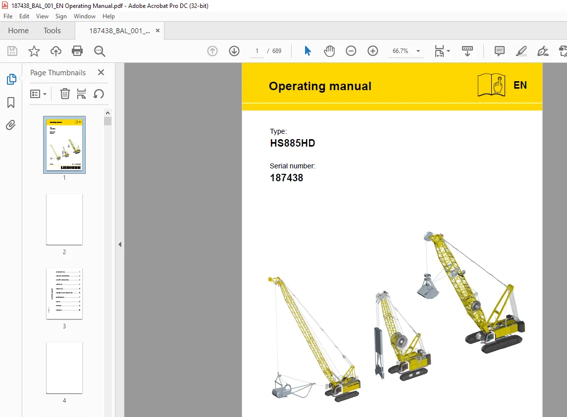
Liebherr Crawler Crane HS885HD Operating Manual SN187438 – PDF DOWNLOAD
$31.95
Liebherr Crawler Crane HS885HD Operating Manual SN187438 – PDF DOWNLOAD
Description
Liebherr Crawler Crane HS885HD Operating Manual SN187438 – PDF DOWNLOAD
FILE DETAILS:
Liebherr Crawler Crane HS885HD Operating Manual SN187438 – PDF DOWNLOAD
Language : English
Pages : 689
Downloadable : Yes
File Type : PDF
DESCRIPTION:
Liebherr Crawler Crane HS885HD Operating Manual SN187438 – PDF DOWNLOAD
INTRODUCTION
1.1 Foreword
The Liebherr name not only stands for products and services. It has become well known for ideas and innovations. For progress, which has proven itself in the market. We continuously expand and improve our wide variety of product and service offering with great intensity. To do so, the constant cooperation and the experience exchange with our customers and business partners all over the world is a prerequisite. For that reason we are thankfull for every suggestion and recommendation for improvement.
SAFETY PRECAUTIONS
3.1 General
Your safety – as machine operator or maintenance technician – is of the utmost priority. Many
situations, problems or malfunctions occurring on the machine can pose a serious risk to safety if
you are not fully familiar with the actions to be taken to prevent and avert possible dangers.
This chapter
– contains information on intended uses,
– contains generally valid information on safety and safety guidelines,
– explains the meaning of symbols and pictograms used in this operating manual and
in the signs on the machine
– provides information about the necessary protective equipment and which requirements apply
to the operating and maintenance personnel,
– shows the location of the safety and monitoring devices on the machine,
– gives information concerning dangers and other risks which can also occur even when the
machine is being operated properly.
Special handling and situation-specific notes on safety are specified where relevant in the following
chapters of this operating manual and in further sections of the documentation included on delive
IMAGES PREVIEW OF THE MANUAL:
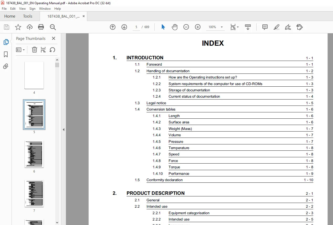
TABLE OF CONTENTS:
Liebherr Crawler Crane HS885HD Operating Manual SN187438 – PDF DOWNLOAD
1 INTRODUCTION 19
1 1 Foreword 19
1 2 Handling of documentation 20
1 2 1 How are the Operating instructions set up? 21
1 2 2 System requirements of the computer for use of CD-ROMs 21
1 2 3 Storage of documentation 21
1 2 4 Current status of documentation 22
1 3 Legal notice 23
1 4 Conversion tables 24
1 4 1 Length 24
1 4 2 Surface area 24
1 4 3 Weight (Mass) 25
1 4 4 Volume 25
1 4 5 Pressure 25
1 4 6 Temperature 26
1 4 7 Speed 26
1 4 8 Force 26
1 4 9 Torque 26
1 4 10 Performance 27
1 5 Conformity declaration 28
2 PRODUCT DESCRIPTION 33
2 1 General 33
2 2 Intended use 34
2 2 1 Equipment categorisation 35
2 2 2 Intended use 37
2 2 3 Improper use 38
2 3 Machine overview 39
2 4 Boom 40
2 4 1 Boom designations 40
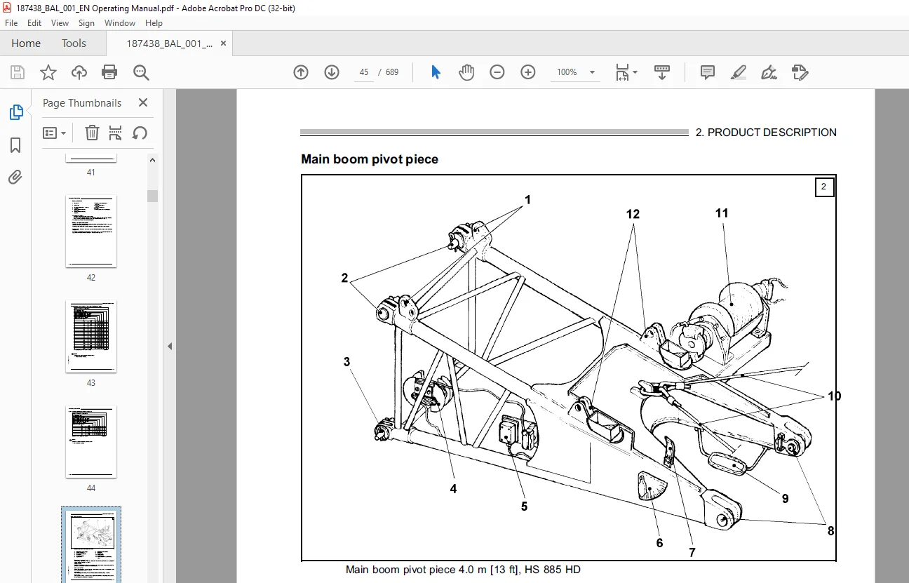
2 4 2 Main boom 41
2 5 Superstructure 56
2 6 Central power unit 58
2 7 Undercarriage 61
2 8 Ballast 63
2 8 1 Rear counterweight 63
2 9 Technical data 64
2 9 1 Dimensions and weights 64
2 9 2 Operating conditions 71
2 9 3 Emissions 71
2 9 4 Engine aggregate 72
2 9 5 Hydraulic system 73
2 9 6 Winches 74
2 9 7 Slewing gear 75
2 9 8 Travel gear 75
2 9 9 Control 76
3 SAFETY PRECAUTIONS 81
3 1 General 81
3 1 1 Danger symbols 82
3 1 2 Appropriate use 83
3 2 Areas of responsibility 83
3 3 Personal attributes required of the machine operator 84
3 4 Personal protective gear 85
3 5 Work area 86
3 6 Safety and monitoring devices 87
3 6 1 Safety devices 87
3 6 2 Monitoring devices 89
3 7 Safety signs on the machine 90
3 7 1 Meaning of the safety signs 93
3 8 Machine-specific dangers 96
3 8 1 Injuries resulting from operating machinery 96
3 8 2 Injuries due to hydraulic energy 98
3 8 3 Risk of burns 99
3 8 4 Risk of chemical burns 100
3 8 5 Fire and explosion hazards 101
3 8 6 Risk of poisoning and asphyxiation 104
3 8 7 Safety Precaution for using refrigerants 105
3 8 8 Electromagnetic influences 107
3 8 9 Endangering the environment 108
3 9 Additional dangers 109
3 9 1 Influence of winds and storms 109
3 9 2 Ground composition at the site 114
3 9 3 Danger zone 115
3 9 4 Snow and ice loads 116
3 9 5 Lightning strikes 117
3 9 6 Overhead power lines 118
3 9 7 Underground pipes and cables 127
3 10 Safety precautions for the machine operator 132
3 11 Safety precautions for maintenance and repair personnel 132
3 12 Safety precautions for construction site personnel 133
3 12 1 Signalman 133
3 12 2 Rigger 135
3 12 3 Hand signals 135
4 CONTROL AND OPERATING ELE- MENTS 147
4 1 General 147
4 2 Operational controls on the undercarriage 148
4 3 Operational controls on the superstructure 149
4 4 Cab 150
4 4 1 Cab overview 150
4 4 2 Overview of the control stand 152
4 4 3 Overhead view of control stand 154
4 4 4 Joysticks, pedals, handwheels 157
4 5 Left-hand control panel (X11) 158
4 6 Left-hand control panel (X12) 160
4 7 Right-hand control panel (X23) 162
4 7 1 Emergency shut-down switch 168
4 8 Operating elements in switch cabinet (X1) 169
4 9 LCD screen 170
4 10 Overview of the LCD screen 172
4 10 1 Main areas of the screen 172
4 10 2 Description of the screen’s main areas 172
4 10 3 Screen sequence 174
4 11 Set-up screens 176
4 11 1 Main boom set-up screen 177
4 11 2 Set-up screen 3 for main boom with fixed fly jib 181
4 12 “Mode screen” screen 183
4 13 “Operating modes” screen 191
4 14 “Power unit monitoring” page 193
4 15 Motor error message 197
4 15 1 Serious motor error message 197
4 15 2 General motor error message 198
4 16 “Fault monitor” page 199
4 17 “Load capacity chart ” page 201
4 18 Litronic service panel on the LCD screen 203
4 18 1 Menu bar 203
4 18 2 Keyboard menu 204
5 OPERATION 209
5 1 General 209
5 1 1 Safe working with the machine 209
5 2 Checks before daily operation 210
5 2 1 Tour of inspection 210
5 2 2 Checks 210
5 3 Daily start up 212
5 3 1 Battery main switch 212
5 3 2 Switching on the ignition 212
5 3 3 Confirming the existing set-up 212
5 3 4 Checking the fuel level 215
5 3 5 Refueling the machine 215
5 3 6 Select operating mode 216
5 3 7 Select operating mode on the left hand con- trol desk (X12 217
5 3 8 Select an operating mode in the “Operating modes” screen 221
5 4 Starting the diesel engine 225
5 4 1 Prerequisites 225
5 4 2 Adjusting the engine speed 227
5 4 3 Lower safety lever (access lever) 229
5 5 Machine operation – main functions 231
5 5 1 Checks/activities on start-up 231
5 5 2 Adjusting the main boom 233
5 5 3 Using the electronic load moment limiter (LML) 235
5 5 4 Load pick-up equipment 237
5 5 5 Resetting the load capacity display to zero (taring) 237
5 6 Operating the hoisting winches 239
5 7 Fast winches 243
5 7 1 General 243
5 7 2 Preselection 243
5 7 3 Activating the slewing gear 245
5 7 4 Slewing gear free-wheel 248
5 7 5 Travelling with the machine 250
5 7 6 Travel gear overdrive 253
5 7 7 Free-fall operation 255
5 7 8 Working in free-fall operation 261
5 7 9 Shutting down free-fall operation 262
5 7 10 Winch standstill monitoring 262
5 7 11 Lowering control (SWG control unit) 263
5 7 12 Interlock control 265
5 7 13 Winch synchronization (optional) 267
5 7 14 Ramming control/chisel control 268
5 7 15 Casing oscillator 275
5 8 Litronic ® test system 279
5 8 1 Properties 279
5 8 2 General 279
5 8 3 Starting the Litronic ® test system 280
5 8 4 The menus 281
5 8 5 Main menu 281
5 8 6 INPUT/OUTPUT menu 282
5 8 7 MEMORY menu 282
5 8 8 SELECT menu 283
5 8 9 CORRECTION menu 286
5 8 10 MESSAGES menu 287
5 8 11 SPECIAL FUNCTIONS menu 288
5 9 Operating the machine – auxiliary func- tions 293
5 9 1 Adjusting the driver’s seat 293
5 9 2 LCD screen adjustments 293
5 9 3 Windshield wiper 294
5 9 4 Lighting 295
5 9 5 Radio 296
5 9 6 Hooter 296
5 9 7 Ashtray 297
5 9 8 Cigarette lighter and socket in the cab 297
5 10 Shutting down the machine 298
5 10 1 Laying down the boom 299
5 10 2 Shutting down the diesel engine 300
5 10 3 Park position of the ignition starter switch 300
5 10 4 Checks before leaving the machine 301
5 11 Emergency control system 302
5 11 1 General 302
5 11 2 Safety instructions 302
5 11 3 Functions of the control desk 303
5 11 4 Connecting the control desk to the emer- gency control sy 304
5 11 5 Instructions for emergency operation 304
6 ASSEMBLY AND DISMANTLING 309
6 1 General 309
6 2 Operational planning 310
6 2 1 Defining the working range 310
6 2 2 Defining the set-up 320
6 2 3 Assembling and preparing the transport equipment 320
6 2 4 Required hoisting rope length 321
6 3 Safety precautions for assembly, dismantling and reconfiguri 323
6 3 1 Requirements for the erecting team 323
6 3 2 Requirements for the site 323
6 3 3 Rules for executing the work 324
6 4 Information on set-up mode 325
6 4 1 Operation in set-up mode 325
6 5 Unloading the basic machine 326
6 5 1 Prerequisites 326
6 5 2 Overview 327
6 5 3 Preparing for assembly mode 329
6 5 4 Platform on the cab 330
6 5 5 Starting assembly mode 331
6 5 6 Prepare assembly crane 334
6 5 7 Erecting the A-frame 335
6 5 8 Drive the machine off the low-loader 337
6 5 9 Removing the superstructure locking 339
6 5 10 Adjust crawler carrier on work track 341
6 5 11 Attaching steps and ladders 345
6 5 12 Platforms on the superstructure 345
6 5 13 Unloading the rear counterweight 347
6 5 14 Location of the rope pulleys on the rear counterweight 348
6 5 15 General 349
6 5 16 Mounting the rear counterweight (Figure 33) 350
6 6 Assembling the main boom 354
6 6 1 Prerequisites 354
6 6 2 Overview of assembly stages 354
6 6 3 Unloading and positioning the boom head 355
6 6 4 Assembling the main boom 355
6 6 5 Assembling the main boom 356
6 6 6 Attaching the main boom to the pivot piece 361
6 6 7 Luffing the hoisting rope 365
6 6 8 Rope reeving plans 366
6 6 9 Connecting the electrics 368
6 7 Hoisting limit switch 371
6 7 1 Snap hook on hoisting limit switch weight (wedge) 373
6 7 2 Erecting the main boom 375
6 7 3 Erecting procedure 377
6 7 4 Cancelling mounting mode 378
6 8 Dismantling the main boom 379
6 8 1 Prerequisites 379
6 8 2 Overview of dismantling stages 379
6 8 3 Preparations in lifting operation 380
6 8 4 Select assembly mode 380
6 8 5 Lay down the main boom 381
6 8 6 Laying down procedure 383
6 8 7 Disconnecting the electrics 384
6 8 8 Pulling out the hoisting ropes 386
6 8 9 Detaching the main boom from the pivot piece 387
6 8 10 Dismantling the main boom 391
6 9 Dismantling the basic machine 392
6 9 1 Prerequisites 392
6 9 2 Overview of dismantling stages 393
6 9 3 Set down the rear counterweight 394
6 9 4 Loading the rear counterweight 397
6 9 5 Fitting the superstructure locking 398
6 9 6 Platforms on the superstructure 399
6 9 7 Remove steps and ladders 399
6 9 8 Adjusting crawler carrier on transport track 401
6 9 9 Drive the machine onto the low-loader 405
6 9 10 Setting down the A-frame 406
6 9 11 Taking the basic machine out of operation 407
6 10 Transport 408
6 10 1 Safety precautions for loading and unloading 408
6 10 2 Transporting the basic machine with a low-loader 409
6 10 3 Transporting fittings 411
6 10 4 Loading the basic machine with an auxiliary crane 413
6 10 5 Transporting overseas 415
7 MAINTENANCE 419
7 1 General 419
7 1 1 Lubricants 420
7 1 2 Welding work 420
7 1 3 Cylinder 420
7 2 Maintenance chart 421
7 2 1 Work to be carried out 421
7 3 Diesel engine 435
7 3 1 Engine; check oil level and oil pressure 435
7 4 Fuel system (MAN engine) 437
7 4 1 Check the water separator on the fuel prefilter, drain off 438
7 4 2 Draining condensate from the fuel filter 440
7 4 3 Draining condensate from the fuel tank 442
7 4 4 Cleaning the fuel prefilter 444
7 4 5 Replacing the fuel filter 446
7 4 6 Bleeding the fuel system 448
7 5 Cooling system 450
7 5 1 Check coolant level, top up if necessary 450
7 6 The dry air filter 451
7 6 1 Arrangement on the central power unit 451
7 6 2 Emptying the dust collection container 451
7 7 Power divider 452
7 7 1 General 452
7 7 2 Checking the gearbox oil level 452
7 7 3 Draining the gearbox oil 453
7 7 4 Refilling the gearbox oil 453
7 7 5 Recommendation for servicing 453
7 7 6 Gearbox oil cooler 453
7 8 Travel gear 454
7 8 1 Cleaning the travel gear 454
7 8 2 Check the chain tension, retighten if neces- sary 454
7 8 3 Slackening the chain 455
7 8 4 Floor plates 455
7 9 Hydraulic system 456
7 9 1 General 457
7 9 2 Checking the oil level 457
7 9 3 Filling with hydraulic oil 457
7 9 4 Cleaning the magnet plug 458
7 9 5 Suction pipe shut-off valve on hydraulic tank 459
7 9 6 Checking the hydraulic system 461
7 9 7 Special maintenance activities 461
7 10 Slewing gear transmission/Rotary connection 462
7 10 1 Slewing gear transmission, checking the oil level 462
7 10 2 Lubricating the crown gear/pinion 462
7 10 3 Lubricating the slew ring bearing races 462
7 11 Winches 463
7 11 1 Checking oil level of winches 1 and 2 and main boom adjus 463
7 11 2 Lubrication points on the main boom adjusting winch 464
7 11 3 Needle bearing 464
7 11 4 Counter bearing 464
7 11 5 Torque support 464
7 11 6 Balancing rocker 464
7 11 7 Main boom adjusting winch and A-frame; Rope deflection pu 464
7 12 Ropes and pulleys 465
7 12 1 Checking the rope against end of service life criteria 465
7 12 2 Check the rope for diameter shrinkage 466
7 12 3 Check for rope deformations 467
7 12 4 Check ropes for corrosion 468
7 12 5 Check ropes for abrasion 469
7 12 6 Check ropes for the effects of heat 469
7 12 7 Check the rope for number of permitted wire breaks 471
7 12 8 Selecting a rope 472
7 12 9 Storing ropes 476
7 12 10 Transporting ropes 477
7 12 11 Checking the rope drive 477
7 12 12 Winding ropes 481
7 12 13 Luffing ropes 483
7 12 14 Lubricating ropes 485
7 12 15 Check rope suspensions and fastenings 485
7 12 16 Checking the pocket locks 486
7 12 17 Check the rope fixation and rope thimble 487
7 13 Load hook 489
7 13 1 Load hooks with one or more pulleys 489
7 13 2 Single hook 489
7 14 Maintaining the CFK pendant straps 491
7 14 1 Arrangement of pendant straps 492
7 14 2 Checking the pendant straps 492
7 14 3 Checks 492
7 14 4 Wear to the protective sheath 493
7 14 5 Checking the pendant strap bushes 493
7 14 6 Parallel flanges 493
7 14 7 Checking the connecting pins 494
7 14 8 Inspecting the coupling links 494
7 14 9 Replacing the pendant straps 494
7 14 10 Transporting the pendant straps 494
7 15 Boom maintenance 496
7 15 1 Boom pivot piece 496
7 15 2 Boom intermediate pieces 496
7 15 3 Main boom head 496
7 15 4 Checking the boom bolting and main boom guy ropes / ancho 497
7 16 Electrical system 499
7 16 1 Checking displays, lighting etc 499
7 16 2 Boom limit switch 500
7 16 3 Hoisting limit switch 500
7 16 4 Slip ring carrier * 501
7 16 5 Battery main switch 501
7 17 Cab 503
7 17 1 Windshields 503
7 17 2 Cab door and door lock 503
7 17 3 Inside and outside mirrors 503
7 17 4 Hydraulic height adjustment of the cab (optional) 504
7 17 5 Hydraulic cab adjustment 504
7 18 Personal protective gear 505
7 19 Lubricant requirements 506
7 19 1 Rapidly biodegradable hydraulic oils 507
7 20 Hydraulic oil (initial filling) 508
7 21 Diesel fuels 508
7 22 Diesel engine lubricating oils 509
7 23 Coolant 511
7 23 1 Fresh water guidelines: 511
7 24 Diesel engine coolant 512
7 25 Capacities 515
7 26 Lubrication chart 516
7 27 Repair-welding 519
8 REPAIR 523
8 1 General 523
8 2 Fire extinguishers 525
8 2 1 General 525
8 3 Personal protective gear 525
8 3 1 General 525
8 4 Conservation regulations 525
8 4 1 General 525
8 5 Resale – Decommissioning 525
8 5 1 General 525
9 OPTIONS 531
9 1 General 531
9 2 Boom walkways 532
9 3 Diagonal protection set 533
9 3 1 General 533
9 4 Rope brackets 534
9 5 Heating and air conditioning system 535
9 5 1 General 535
9 5 2 Air conditioning system units 535
9 5 3 Operation 536
9 5 4 Information on the use of the heating and air conditioning 537
9 6 Rope pull limitation, hoisting winch 1 + 2 539
9 7 GSM Service Modem 541
9 8 3-windings limit switch 542
9 8 1 General 542
9 8 2 Setting the 3-windings limit switch 542
9 9 Central lubrication of the slewing ring bearings 543
9 9 1 General 543
9 9 2 Filling the grease container 544
9 9 3 Time interval programming 544
9 9 4 Function 545
9 9 5 Maintenance of the central lubricating system 545
9 10 Central lubrication of the tooth flanks of the slewing ring 546
9 10 1 General 546
9 10 2 Filling the grease container 547
9 10 3 Time interval programming 547
9 10 4 Function 548
9 10 5 Maintenance of the central lubricating system 548
9 11 Refuelling pump 549
9 11 1 General 550
9 11 2 Refuelling 550
9 12 Pay out metering 553
9 12 1 General 553
9 12 2 Displays in the mode screen 553
9 12 3 Programming rope length 553
9 13 Process data acquisition (PDE) 555
9 13 1 General 555
9 13 2 Data evaluation 556
9 13 3 PDE monitor 557
9 13 4 Operation 567
9 13 5 Data organization 570
9 13 6 Printer 571
9 14 Winch synchronization 573
9 14 1 General 573
9 14 2 Switching on winch synchronization 573
9 14 3 Switching off winch synchronization 573
9 15 Hydraulic cab elevation 575
9 15 1 Product description 575
9 15 2 Safety devices 576
9 15 3 Operation 580
9 15 4 Maintenance 582
9 16 Bypass filter 585
9 16 1 General 585
9 16 2 Functioning 585
9 16 3 Maintenance 585
9 17 Pressure filter refuelling system 587
9 17 1 General 587
9 18 Falling rock protection 589
9 18 1 General 589
9 18 2 Arrangement 589
9 19 Falling rock protection 591
9 19 1 General 591
9 19 2 Arrangement 591
9 20 Additional floodlight at the uppercarriage 593
9 20 1 Arrangement 593
9 20 2 Operating Elements 593
9 21 Additional winch 595
9 21 1 Preselecting the additional winch 596
9 21 2 Deselecting the additional winch 597
9 21 3 Transporting personnel 598
9 21 4 Instructions for using the additional winch for carrying 598
9 21 5 Additional winch emergency lowering 598
9 22 Names of measuring points 601
9 22 1 General 601
9 23 Pump wear indication 603
9 23 1 General 603
9 23 2 Checking the contamination monitor 604
9 24 Orthopedic driver’s seat 605
9 24 1 General 605
9 25 Auxiliary winch 607
9 25 1 General 607
9 25 2 Technical data 607
9 26 Rope run 608
9 26 1 Checks before start up 609
9 26 2 Operating the auxiliary winch 609
9 26 3 Maintenance of the auxiliary winch 611
9 27 Cold weather kit 613
9 27 1 General 613
9 27 2 Off-duty heating General 614
9 27 3 Heating the hydraulic oil 615
9 28 Roof railing 617
9 28 1 General 617
9 28 2 Location 617
9 28 3 Fastening 618
9 28 4 Chopper bar 618
9 29 Additional indicator unit 619
9 29 1 General 619
9 29 2 Arrangement 619
9 29 3 Signal column 620
9 30 Warning light and horn 621
9 30 1 General 621
9 30 2 Function 621
9 31 Video monitoring system 623
9 32 Vibrator 627
9 32 1 General 627
9 32 2 Operational controls 628
9 32 3 Connecting the hydraulic system 630
9 32 4 Select vibrator operation 632
9 32 5 “Vibrator operation” screen 635
9 32 6 Settings 636
9 32 7 Operating the vibrator 638
9 32 8 Deselecting “Vibrator operation” 641
9 32 9 Maintenance of the attached vibrator 641
9 33 Hammer 643
9 33 1 General 643
9 33 2 Operational controls 644
9 33 3 Connecting the hydraulic system 646
9 33 4 Select hammer operation 647
9 33 5 “Hammer operation” screen 651
9 33 6 Settings 652
9 33 7 Operating the hammer 654
9 33 8 Deselecting “Hammer operation” 655
9 33 9 Maintenance of the attached hammer 655
9 34 Diaphragm wall grab 657
9 34 1 General 657
9 34 2 Connecting the grab 661
9 34 3 Operational controls 662
9 34 4 Right-hand control panel (X23) 664
9 34 5 Select grab operation 667
9 34 6 “Grab” screen 670
9 34 7 Operating the grab 672
9 34 8 Deselecting the grab 681
9 34 9 Detaching the grab 681
9 34 10 Grab maintenance 682
10 APPENDIX 687
10 1 General 687
Questions? Email us: [email protected]
PLEASE NOTE:
- This is the SAME exact manual used by your dealers to fix your vehicle.
- The same can be yours in the next 2-3 mins as you will be directed to the download page immediately after paying for the manual.
- Any queries / doubts regarding your purchase, please feel free to contact [email protected]
S.M