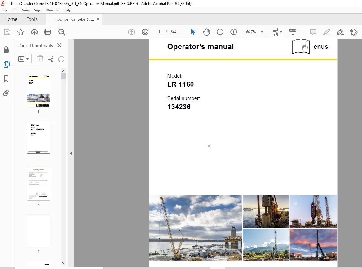
Liebherr Crawler Crane LR 1160 Operators Manual SN 134236 – PDF DOWNLOAD
$25.95
Liebherr Crawler Crane LR 1160 Operators Manual SN 134236 – PDF DOWNLOAD
Description
Liebherr Crawler Crane LR 1160 Operators Manual SN 134236 – PDF DOWNLOAD
FILE DETAILS:
Liebherr Crawler Crane LR 1160 Operators Manual SN 134236 – PDF DOWNLOAD
Language : English
Pages :1644
Downloadable : Yes
File Type : PDF
DESCRIPTION:
Liebherr Crawler Crane LR 1160 Operators Manual SN 134236 – PDF DOWNLOAD
Foreword
- The name Liebherr doesn’t just stand for products and services. It has become a byword for ideas and innovations. For progress which has proved its worth in the marketplace.
- We constantly strive to extend and improve our diverse range of products and services.
- This requires ongoing cooperation and sharing of experience with our customers and business partners throughout the world.
- We are therefore grateful for any ideas and suggestions for improvements. Inform Liebherr customer service if the machine is sold or bought by a previous owner
IMAGES PREVIEW OF THE MANUAL:
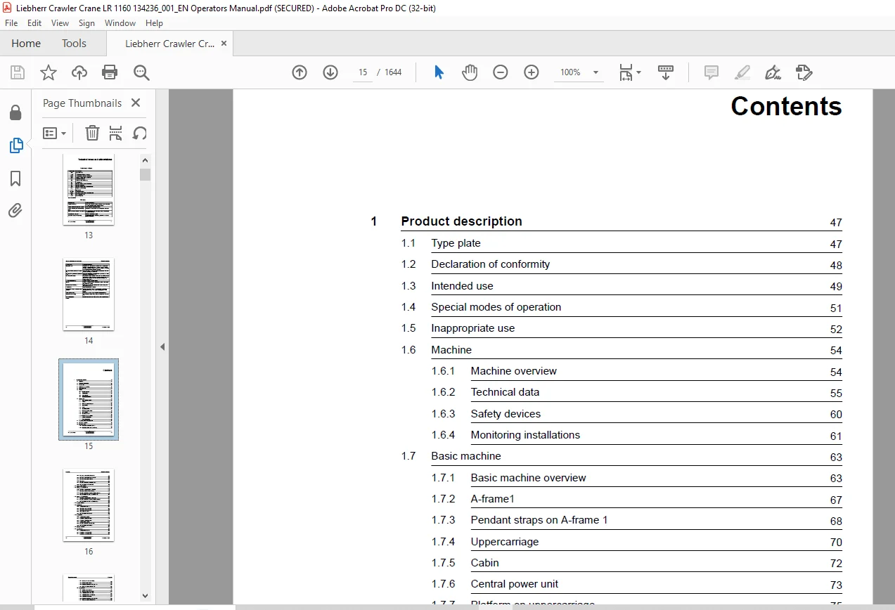
TABLE OF CONTENTS:
Liebherr Crawler Crane LR 1160 Operators Manual SN 134236 – PDF DOWNLOAD
Operator’s manual 1
Foreword 5
Notes regarding the documentation 7
Technical terms and abbreviations 13
Contents 15
1 Product description 49
1 1 Type plate 49
1 2 Declaration of conformity 50
1 3 Intended use 51
1 4 Special modes of operation 53
1 5 Inappropriate use 54
1 6 Machine 56
1 6 1 Machine overview 56
1 6 2 Technical data 57
1 6 3 Safety devices 62
1 6 4 Monitoring installations 63
1 7 Basic machine 65
1 7 1 Basic machine overview 65
1 7 2 A-frame1 69
1 7 3 Pendant straps on A-frame 1 70
1 7 4 Uppercarriage 72
1 7 5 Cabin 74
1 7 6 Central power unit 75
1 7 7 Platform on uppercarriage 77
1 7 8 Undercarriage 78
1 7 9 Crawler side frame 80
1 7 10 Platforms on undercarriage 82
1 7 11 Carbody counterweight 90
1 7 12 Rear counterweight 92
1 8 Information about boom designation 96
1 9 Main boom – overview 98
1 10 Main boom 2018 99
1 10 1 Main boom base section 2018 23 99
1 10 2 Main boom section 2018 20 3 m (10 ft) 101
1 10 3 Main boom section 2018 20 6 m (20 ft) 102
1 10 4 Main boom section 2018 20 11 7 m (38 ft) 104
1 10 5 Main boom head section 2018 20 106
1 10 6 Rope guide 108
1 10 7 Mid-point suspension on main boom 2018 111
1 10 8 Pendant straps on main boom 2018 117
1 11 Reducing piece overview 125
1 12 Reducing adapter 2018/1713 126
1 12 1 2018/1713 20 reducing piece 12 m (40 ft) 126
1 12 2 Main boom section 1713 22 1 m (3 ft) 128
1 12 3 Mid-point suspension on reducing adapter 2018/1713 130
1 12 4 Pendant straps on reducing adapter 2018/1713 142
1 13 Reducing adapter 2018/1309 145
1 13 1 2018/1309 20 reducing piece 7 2 m (23 ft) 145
1 13 2 Mid-point suspension on reducing adapter 2018/1309 147
1 13 3 Pendant straps on reducing adapter 2018/1309 160
1 14 Fixed jib – overview 162
1 15 1008 fixed jib 163
1 15 1 Jib base section 1008 20 163
1 15 2 1008 17 jib section 3 m (10 ft) 165
1 15 3 1008 17 jib section 6 m (20 ft) 166
1 15 4 1008 20 jib head section 167
1 15 5 Pendant straps on fixed jib 1008 168
1 16 Fixed jib 0806 175
1 16 1 Jib base section 0806 16 175
1 16 2 Jib section 0806 15 3 m (10 ft) 176
1 16 3 Jib section 0806 15 6 m (20 ft) 178
1 16 4 Jib head section 0806 16 179
1 16 5 Mid-point suspension on fixed jib 0806 180
1 16 6 Pendant straps on fixed jib 0806 184
1 17 Luffing jib – overview 191
1 18 1713 luffing jib 192
1 18 1 Jib base section 1713 22 192
1 18 2 Jib section 1713 18 3 m (10 ft) 194
1 18 3 Jib section 1713 18 6 m (20 ft) 195
1 18 4 Jib section 1713 18 12 m (40 ft) 197
1 18 5 Jib head section 1713 21 198
1 18 6 Mid-point suspension on luffing jib 1713 200
1 18 7 Pendant straps on luffing jib 1713 206
1 19 1309 luffing jib 213
1 19 1 Jib base section 1309 22 213
1 19 2 Jib section 1309 20 3 m (10 ft) 215
1 19 3 1309 20 jib section 6 m (20 ft) 216
1 19 4 1309 20 jib section 11 7 m (38 ft) 218
1 19 5 1309 22 jib head section 219
1 19 6 Mid-point suspension on luffing jib 1309 221
1 19 7 Pendant straps on luffing jib 1309 227
1 20 Midfall overview 235
1 21 1713 31 Midfall 236
1 21 1 Midfall 1713 31 236
1 21 2 Mid-point suspension on midfall 1713 31 238
1 21 3 Pendant straps on midfall 1713 31 238
1 22 1309 32 Midfall 240
1 22 1 Midfall 1309 32 240
1 22 2 Mid-point suspension on midfall 1309 32 242
1 22 3 Pendant straps on midfall 1309 32 242
1 23 Auxiliary jib* (36 t (79 300 lb)) 244
1 24 Auxiliary jib* (15 t (33 000 lb)) 247
1 25 Rope fixing point 249
1 25 1 Main boom head 249
1 25 2 Fixed jib head section 250
1 25 3 Luffing jib head section 251
1 25 4 Auxiliary jib (36 t (79 300 lb)) on main boom head 252
1 25 5 Auxiliary jib (15 t (33 000 lb)) on jib head section 252
1 25 6 Midfall 253
1 25 7 Pocket lock 253
1 25 8 Cross link 255
1 25 9 Pin for rope fixing point 256
1 26 Pulley block/hook* 257
1 26 1 Pulley block (160 t (352,734 lb)) 257
1 26 2 Pulley block (100 t (220,459 lb)) 259
1 26 3 Pulley block (80 t (176,367 lb)) 261
1 26 4 Pulley block (40 t (88,184 lb)) 263
1 26 5 Hook (12 5 t (27,557 lb)) 265
1 27 Abseil rescue equipment* 267
1 28 Safety barrier* 268
1 29 Suction flap* 269
1 30 Armrests* for operator’s seat 270
1 31 Vertical Line Finder* assistance system 271
1 32 Outside mirror* 273
1 33 Tagline winch* 274
1 34 Refueling pump* 276
1 35 Cab roof protection guard* 277
1 36 Lightning rods* 278
1 37 External power supply* 279
1 37 1 External power supply aircraft warning light 279
1 37 2 External supply low temperature package 281
1 38 Radio remote control* 284
1 39 Foot pedal adjuster* 287
1 40 GSM/GPRS/GPS modem 288
1 41 Virtual Private Network (VPN)* 289
1 41 1 Cisco 3G VPN router 289
1 41 2 SIM card 290
1 41 3 Power unit 290
1 41 4 Cisco 3G antenna 290
1 42 Hook fixing point * 291
1 43 Handrail* / wide steps* 293
1 44 Ventilation, heating and air-conditioning 294
1 44 1 Cooling circuit 295
1 44 2 Heating circuit 300
1 44 3 Auxiliary air heating* 303
1 44 4 Electric components 305
1 44 5 Mechanic components 309
1 45 Aircraft warning light* 310
1 46 Third hoist limit switch* 311
1 47 Hoist limit switch clamp* for auxiliary jib (36 t (79 300 lb)) 312
1 48 Cabin handrail* 313
1 48 1 Cabin handrail variant 1 with undercarriage with carbody counterweight 314
1 48 2 Cabin handrail variant 1 with undercarriage without carbody counterweight 315
1 48 3 Cabin handrail variant 2 with undercarriage with carbody counterweight 317
1 48 4 Cabin handrail variant 2 with undercarriage without carbody counterweight 319
1 49 Cable remote control 322
1 50 Catwalks* for boom 324
1 51 Leak oil return* 326
1 52 Ladder* for boom 327
1 53 Ladder* for uppercarriage 329
1 54 Reading light* for cabin 331
1 55 Litronic control system 332
1 56 Retrofit kits* for operation with two ropes over the jib head section 333
1 56 1 Retrofit kit for luffing jibs 1008 / 1309 / 1713 / 1916 / 2316 333
1 56 2 Retrofit kit for 1008 fixed jib 334
1 56 3 Retrofit kit for 0806 fixed jib 335
1 57 Luffing jib luffing winch as auxiliary winch* 336
1 58 By-pass flow filter system* 337
1 59 Emergency operation control* 338
1 60 Visual motion warning device* 339
1 61 Process data recording (PDE)* 341
1 62 Process data report (PDR)* 342
1 63 Pump wear indicator* 343
1 64 Quick latch couplings* on jib luffing winch 345
1 65 Socket* in cabin 347
1 66 Falling object protection* for cabin 348
1 66 1 Foldable falling object protection* 348
1 66 2 Fixed falling object protection 350
1 67 Vandalism protection* 352
1 67 1 Top cover 353
1 67 2 Rear cover 354
1 67 3 Front cover 355
1 67 4 Right front cover 356
1 67 5 Right rear cover 358
1 67 6 Left front cover 359
1 67 7 Left rear cover 360
1 67 8 Brackets for front cover 361
1 67 9 Barrier rod 361
1 68 Video monitoring system* 363
1 68 1 Cabin overview 363
1 68 2 Machine overview 364
1 68 3 Video surveillance – basic device 365
1 68 4 Video surveillance – boom 367
1 68 5 Quad monitor 368
1 68 6 Camera 370
1 68 7 Control panel zoom camera 371
1 68 8 Zoom camera 372
1 68 9 Mounts 373
1 68 10 Camera cable in main boom base section 379
1 68 11 Zoom camera in main boom head 380
1 68 12 Zoom camera in fixed jib head 381
1 68 13 Zoom camera in luffing jib head 383
1 68 14 Zoom camera in auxiliary jib 36 t (79300 lb) 384
1 68 15 Zoom camera in auxiliary jib 15 t (33000 lb) 384
1 68 16 Foot pedal* for zoom camera 386
1 69 Central lubrication system 387
1 70 Additional floodlights* 388
1 70 1 Floodlights on uppercarriage 388
1 70 2 Floodlight on cabin 390
1 70 3 Adjustable floodlights on main boom base section 391
1 70 4 Floodlights on main boom 392
1 70 5 Floodlight with LED om main boom head* 397
1 70 6 Floodlight with high-pressure sodium vapor lamp on jib head section 398
2 Safety instructions 403
2 1 Safe operation of the machine 403
2 1 1 Personnel selection 403
2 1 2 Safe system of work 403
2 1 3 Preventive maintenance 404
2 2 Areas of responsibility 405
2 2 1 Manufacturer 405
2 2 2 Owner 405
2 2 3 Machine operator 406
2 2 4 Slinger 406
2 2 5 Signaller 407
2 2 6 Maintenance personnel 407
2 2 7 Installation personnel and disassembly personnel 407
2 2 8 Helper 408
2 2 9 Liebherr service personnel 408
2 2 10 Certified and institutionally authorized persons 408
2 3 Requirements to personnel 409
2 3 1 Machine operator 409
2 3 2 Slinger 409
2 3 3 Signaller 410
2 3 4 Maintenance personnel 410
2 3 5 Installation personnel and disassembly personnel 410
2 3 6 Helper 411
2 3 7 Liebherr service personnel 411
2 3 8 Certified and institutionally authorized persons 411
2 4 Personal protective equipment 412
2 5 Workplace 412
2 6 Danger zone 413
2 7 Safety signs on the machine 415
2 8 Safety signs on the machine (US market) 419
2 9 Meaning of the safety signs 424
2 9 1 Mandatory signs 425
2 9 2 Prohibition signs 426
2 9 3 Warning signs 427
2 9 4 Rescue signs 429
2 9 5 Fire protection signs 429
2 10 Meaning of machine-specific signs 429
2 10 1 Safety signs 429
2 10 2 Notice signs 431
2 11 Hazards 434
2 11 1 Mechanical action 434
2 11 2 Electrical energy 435
2 11 3 Hydraulic energy 436
2 11 4 Burns 436
2 11 5 Chemical burns 437
2 11 6 Fire and explosion 438
2 11 7 Poisoning and suffocation 439
2 11 8 Electromagnetic influence 440
2 11 9 Exposure to wind 440
2 11 10 Snow load and ice load 446
2 11 11 Ground bearing strength 447
2 11 12 Lightning strike 448
2 11 13 Overhead lines 449
2 11 14 Environment 451
2 12 What to do in dangerous situations 452
2 12 1 Procedure in event of current transfer 452
2 12 2 How to respond in the event of a fire 453
2 12 3 Firefighting 454
2 13 Working at heights 456
2 14 Application on floating devices 456
2 14 1 Operation of the machine on floating devices 457
2 14 2 Transport of the machine on floating devices 457
2 14 3 Higher risk of machine corrosion on floating devices 458
2 15 Use at low temperatures 458
2 15 1 Operation of the machine down to -20 °C (-4 °F) (standard) 459
2 15 2 Operation of the machine down to -25 °C (-13 °F)* 459
2 15 3 Operation of the machine down to -40 °C (-40 °F)* 460
2 16 Hand signals 460
2 16 1 General hand signals in accordance with BGV A8 461
2 16 2 Special hand signals for sling gear application 463
2 16 3 Hand signals for lifting gear application in accordance with ASME/ANSI B30 5 466
3 Control and operating elements 473
3 1 Operating elements on the undercarriage 474
3 2 Operating elements on the uppercarriage 475
3 3 Cabin 476
3 4 Left control lever 477
3 4 1 Left multi-directional control lever 477
3 4 2 Left multi-directional control lever 482
3 5 Right control lever 488
3 5 1 Right multi-directional control lever 488
3 5 2 Right double T-lever 495
3 6 Foot pedals and hand levers 503
3 7 Circular bubble 505
3 8 Operating hours counter 506
3 8 2 Additional operating hours counter* 506
3 9 Control panel X11 507
3 10 Control panel X12 509
3 11 Control panel X23 511
3 12 Monitor 514
3 12 1 Status bar 514
3 12 2 Display section 522
3 12 3 Menu bar 522
3 12 4 Submenu bar 524
3 13 Screen Start 525
3 14 Operation screen 526
3 15 Power unit screen 535
3 16 Operating hours screen 542
3 17 Setup screen 545
3 17 1 Setup – boom configuration screen 547
3 17 2 Setup – boom configuration 1 screen 548
3 17 3 Setup – boom configuration 2 screen 551
3 17 4 Setup – boom configuration 3 screen 554
3 17 5 Setup – boom configuration 4 screen 559
3 17 6 Setup – boom configuration 5 screen 563
3 17 7 Setup – load chart screen 568
3 18 Screen Working range limitation 570
3 18 1 Screen Working range limitation – working range limitation 570
3 18 2 Screen Working range limitation – lifting height limitation 577
3 19 Screen Access control 580
3 19 1 Without retrofit kit access control (black ignition keys) 580
3 19 2 Without retrofit kit access control (blue ignition keys) 581
3 19 3 With retrofit kit access control (red and blue ignition keys)* 582
3 20 Mode screen 585
3 21 Settings screen 587
3 21 1 Screen Settings – components 587
3 21 2 Settings – units screen 590
3 21 3 Screen Settings – Litronic testing system 593
3 22 Error messages screen 598
3 23 Cable remote control 600
3 23 1 Cable remote control on uppercarriage 600
3 23 2 Cable remote control on undercarriage 600
3 24 Radio remote control* 602
3 24 1 Operating elements 602
3 24 2 Monitor 611
3 25 Emergency operation control* 620
3 26 Control unit external air conditioning system* 622
3 27 Auxiliary heating* control unit 624
3 28 Video monitoring system* 625
3 28 1 Quad monitor 625
3 28 2 Control panel zoom camera 626
3 29 Central lubrication* 628
3 30 Additional floodlights* 629
3 30 1 Cabin 629
4 Operation 633
4 1 Checks before start up 633
4 1 1 Inspecting the machine 634
4 1 2 Checking position of main battery switch 634
4 2 Startup 635
4 2 1 Adjusting the operator’s seat 635
4 2 2 Switching on the ignition 635
4 2 3 Confirming the existing setup 635
4 2 4 Checking the fuel fill level 636
4 2 5 Checking the urea solution fill level 636
4 2 6 Checking the hydraulic oil tank gate valve 636
4 2 7 Starting the diesel engine 637
4 2 8 Adjusting the diesel engine RPM 638
4 2 9 Setting the constant engine RPM 640
4 2 10 Lowering the safety lever 642
4 2 11 Checking the tilting-back support cylinder 642
4 3 Control panels 643
4 3 1 Setting control panel X25* or control panel X26* 643
4 4 Operator’s seat 645
4 4 1 Adjusting the control stand horizontally 646
4 4 2 Adjusting the operator’s seat 646
4 4 3 Adjusting the dampening 650
4 4 4 Adjusting the ergonomics* 651
4 4 5 Safety belt* 653
4 5 Lighting 654
4 5 1 Operating the floodlights on the uppercarriage 654
4 5 2 Operating additional floodlights 654
4 5 3 Operating cabin lighting 655
4 5 4 Operating the engine compartment lighting 655
4 6 Windscreen wiper system 656
4 6 1 Operating the windscreen wipers 656
4 6 2 Operating the windscreen washer system 657
4 7 Ventilation, heating and air-conditioning 658
4 7 1 Setting the air vent 660
4 7 2 Adjusting the lamella vents 661
4 7 3 Setting recirculated air or fresh air 661
4 7 4 Operating the ventilation 661
4 7 5 Using the heater 662
4 7 6 Turning the air conditioning system on or off 662
4 7 7 Operating the external air conditioning system* 663
4 7 8 Auxiliary heating* 670
4 8 Additional cab equipment 674
4 8 1 Using the horn 674
4 8 2 Operating the safety lever 674
4 8 3 Operating the radio 675
4 8 4 Using the ashtray 676
4 8 5 Using the cigarette lighter 677
4 9 Cab tilting device* 678
4 9 1 Tilting the cabin 678
4 10 Central lubrication* 679
4 10 1 Set lubrication time 679
4 10 2 Set pause time 679
4 10 3 Interim lubrication 679
4 11 Mode 680
4 11 1 Turning the assembly functions on or off 680
4 11 2 Selecting mode 680
4 12 Programming the setup 682
4 12 1 Call up the Setup screen 682
4 12 2 Selecting and changing settings 683
4 12 3 Calculating the revised set-up 683
4 12 4 Checking the programed setup 684
4 13 Load moment limitation (LML) 685
4 13 1 General 685
4 13 2 Load moment limitation self-lock 688
4 13 3 Load moment limitation shut-off (CE load chart) 690
4 13 4 Load moment limitation shut-off (ANSI load chart) 691
4 14 Calculating load charts online 693
4 14 1 Calculating load charts 693
4 14 2 Boom configuration 4 – load position 1 694
4 14 3 Boom configuration 4 – load position 2 695
4 14 4 Boom configuration 5 – load position 1 696
4 14 5 Boom configuration 5 – load position 3 697
4 14 6 Boom configuration 6 – load position 2 698
4 14 7 Boom configuration 8 – load position 1 699
4 14 8 Boom configuration 8 – load position 2 700
4 14 9 Boom configuration 9 – load position 1 701
4 14 10 Boom configuration 9 – load position 2 702
4 15 Set the load capacity display to zero (taring) 703
4 15 1 Setting the load display of winch1 or winch2 to zero 703
4 16 Single hook operation/two-hook operation 704
4 16 1 Single-hook mode with one winch on one hook 706
4 16 2 Single-hook mode with two winches on one hook 708
4 16 3 Single-hook mode with two winches on two hooks 709
4 16 4 Twin-hook mode with two hooks on two loads 715
4 16 5 Twin-hook mode with two hooks on one load 717
4 17 Crawlers 722
4 17 1 Setting the crawler speed 722
4 17 2 Operating the travel gear 722
4 17 3 Locking or unlocking the crawler 726
4 18 Swing gear 728
4 18 1 Setting the swing speed 728
4 18 2 Turning the swing gear free-wheel on or off 729
4 18 3 Operating the swing gear 730
4 18 4 Locking or unlocking the swing gear 734
4 19 Main boom 735
4 19 1 Operating the main boom 735
4 19 2 Locking or unlocking the main boom 739
4 20 Jib 740
4 20 1 Selecting the jib 740
4 20 2 Operating the jib 741
4 21 Winch 1/Winch 2 746
4 21 1 Operating winch 1 746
4 21 2 Operating winch 2 750
4 21 3 Locking or unlocking winch1/winch2 754
4 22 Free-fall mode* 756
4 22 1 Activating free-fall mode 756
4 22 2 Selecting free-fall mode 757
4 22 3 Operating free-fall mode 757
4 22 4 Deactivating free-fall mode 760
4 23 Winch synchronization* 762
4 23 1 Activating winch synchronization 762
4 23 2 Operating the winch synchronization 763
4 23 3 Deactivating winch synchronization 765
4 24 Blocked crawlers* 766
4 24 1 Driving onto the support plates 767
4 24 2 Working with Blocked Crawlers 768
4 25 Assembly cylinder * 770
4 25 1 Select assembly cylinder 770
4 25 2 Operating the assembly cylinder 770
4 26 Filling the machine with fuel 773
4 26 1 Filling the fuel tank 773
4 26 2 Filling up with urea solution* 774
4 27 Radio remote control* 775
4 27 1 Battery 775
4 27 2 Battery charger 775
4 27 3 Starting the machine with the radio remote control 777
4 28 Rope measuring system* 783
4 28 1 Setting the rope length to zero 783
4 28 2 Calibrating the rope measuring system 783
4 29 Ground pressure display* 785
4 29 1 Operating the ground pressure display 785
4 30 Inclination display* 786
4 30 1 Operating the inclinometer 786
4 31 Load recorder* 787
4 31 1 Setting trigger points 787
4 31 2 Operating the load recorder 787
4 32 Working range limitation* 790
4 32 1 Operating the edge limitation 790
4 32 2 Operating the sector limitation 792
4 32 3 Operating the radius limitation 794
4 32 4 Operating the slewing range limitation 797
4 32 5 Operating the lifting height limitation 798
4 32 6 Cancelling the stop after crawler operation 800
4 32 7 Resetting limitations 800
4 33 Assistance system horizontal load path* 801
4 33 1 Activating horizontal load path 801
4 33 2 Activating horizontal load path 802
4 33 3 Deactivating horizontal load path 804
4 34 Assistance system Vertical Line Finder* 805
4 34 1 Setting offsets of the Vertical Line Finder to zero 805
4 34 2 Activating the positioning of boom head above load’s center of gravity 805
4 34 3 Positioning boom head above load’s center of gravity 805
4 34 4 Deactivating positioning of boom head above load’s center of gravity 806
4 35 Rope reeving winch 807
4 35 1 Setting the rope reeving winch to free-wheel 807
4 35 2 Deactivating rope reeving winch free-fall 808
4 35 3 Reeving the rope of the rope reeving winch 808
4 36 Tagline winch* 809
4 36 1 Putting the tagline winch into operation 809
4 36 2 Turn the tagline winch on or off 810
4 36 3 Set the constant tension of the tagline winch 810
4 36 4 Setting the pull force of the tagline winch 811
4 36 5 Select maximum pull force of the tagline winch 812
4 36 6 Turning tagline winch free-wheel on or off 812
4 37 Luffing jib luffing winch as auxiliary winch* 814
4 37 1 Use as jib luffing winch 814
4 37 2 Use as leader height adjusting winch 815
4 37 3 Use as auxiliary winch 815
4 38 Diesel engine automatic stop system* 816
4 38 1 Switching the diesel engine automatic stop system on or off 816
4 39 ECO mode* 817
4 39 1 ECO mode operation 817
4 40 Sensitive hoisting* 818
4 40 1 Turning the function sensitive lift on or off 818
4 40 2 Operating sensitive hoisting 818
4 41 Abseil rescue equipment* 819
4 41 1 Using abseil rescue equipment 819
4 42 Emergency stop 821
4 42 1 Using emergency stop 821
4 43 Shutdown 822
4 43 1 Short work interruption 822
4 43 2 Long work interruption 823
4 43 3 Switching off battery main switch 824
4 44 Hydraulic emergency mode* 825
4 44 1 Winch 2 emergency mode 825
4 44 2 Main boom adjusting winch emergency mode 827
4 44 3 Swing emergency mode 828
4 45 Emergency operation control* 831
4 45 1 Operating the emergency control 831
5 Operational faults, diagnosis 835
5 1 Malfunctions 835
5 1 1 Identifying faults 835
5 1 2 Error displays on monitor 835
5 1 3 Troubleshooting 840
5 2 Litronic testing system 841
5 2 1 Litronic testing system overview 841
5 2 2 Screen pages 842
5 2 3 Starting the Litronic testing system 849
5 3 Fuses 850
5 3 1 List of fuses 850
5 3 2 Checking fuses 852
5 3 3 Changing fuses 854
6 Operational planning 857
6 1 Assembly site 857
6 2 Tools required 859
6 2 1 Machine with self-assembly system 859
6 2 2 Machine without self-assembly system 859
6 3 Required length of winch1/winch2 rope 860
6 3 1 Calculating the length of winch1/winch2 rope 860
6 4 Choosing the correct hook or pulley block 862
6 5 Positioning the hook or pulley block 865
6 6 Restrictions from exposure to wind 866
6 6 1 Erecting the boom 866
6 6 2 Reducing the lifting capacity 866
6 6 3 Parking positions for boom configurations 876
6 6 4 Laying down the boom 880
6 7 Traveling on gradients 881
6 8 Rigging material 900
6 8 1 4-strand round sling gear with chain shortening devices 901
6 8 2 Round slings 901
6 8 3 Shackle 902
6 8 4 Other lifting devices 902
7 Assembly and dismantling 907
7 1 Explanation of symbols used 907
7 2 Work instructions for assembly/disassembly 909
7 3 Locking elements – overview 910
7 3 1 Splint pin 910
7 3 2 Linchpin 911
7 3 3 Spring cotter pin 912
7 3 4 Locking spring 913
7 3 5 Locking washers 915
7 4 Assembling the basic machine 916
7 4 1 Notes 916
7 4 2 Moving cabin platforms* into working position 916
7 4 3 Swivel the cab to the working position 920
7 4 4 Mounting the cabin handrail* 922
7 4 5 Ladder for cabin 938
7 4 6 Putting the load moment limiter lamp and flashing light into working position 941
7 4 7 Mounting the boom walkway on the uppercarriage 941
7 4 8 Mounting the ladder on the uppercarriage 942
7 4 9 Mounting the uppercarriage railing 943
7 4 10 Fitting the exhaust pipe 948
7 4 11 Checking the position of the bypass plug 950
7 4 12 Putting the machine into operation 951
7 4 13 Switching on assembly mode functions 952
7 4 14 Switching on cylinder adjustment functions 952
7 4 15 Extend the tilting back support cylinders 952
7 4 16 Erecting A-frame 1 953
7 4 17 Unloading the machine 955
7 4 18 Removing the uppercarriage locking device 965
7 4 19 Stow away uppercarriage locking device 966
7 4 20 Rigging and lifting the main boom base section 966
7 4 21 Attaching the main boom base section to the uppercarriage 969
7 4 22 Connecting hydraulic lines to the uppercarriage 973
7 4 23 Connecting electric cables to the uppercarriage 977
7 4 24 Bolting the equalizer on A-frame1 to the main boom boom base section 979
7 4 25 Loosen the assembly cylinder from the main boom base section 980
7 4 26 Installing the crawler side frame 984
7 4 27 Connecting the hydraulic lines of the crawler 996
7 4 28 Unfolding steps from transport position 999
7 4 29 Move the jack into the transport position 999
7 4 30 Using the machine as assembly crane 1003
7 4 31 Attaching the carbody counterweight 1005
7 4 32 Installing platform on undercarriage 1010
7 4 33 Fitting the rear counterweight 1016
7 5 Main boom 2018 1029
7 5 1 Configuration of main boom 1029
7 5 2 Lengths of mid-point suspensions 1030
7 5 3 Overview of main boom 2018 pendant straps 1031
7 5 4 Reeving diagrams for one rope across main boom head 2018 (load position 1) 1033
7 5 5 Reeving diagrams for two ropes across main boom head 2018 (load position1) 1036
7 5 6 Reeving diagrams for one rope across auxiliary jib (36 t (79300 lb)) on main boom head 2018 (load position1) 1039
7 5 7 Reeving diagrams for two ropes across auxiliary jib (36 t (79300 lb)) and main boom head 2018 (load position 1) 1041
7 5 8 Reeving diagram – jib luffing winch as auxiliary winch 1042
7 6 Assembling the main boom 1044
7 6 1 Notes 1044
7 6 2 Programming the setup 1044
7 6 3 Unloading and positioning the main boom section 1044
7 6 4 Mounting ladder* for boom 1045
7 6 5 Pinning the main boom head to the main boom sections 1047
7 6 6 Connecting catwalks* for booms 1049
7 6 7 Connecting and checking boom fall arrest* 1051
7 6 8 Installing the rope guide 1051
7 6 9 Pinning pendant straps 1053
7 6 10 Installing jib backstay straps 1054
7 6 11 Installing the mid-point suspension 1055
7 6 12 Bolting the main boom base section to the main boom 1058
7 6 13 Bolting the equalizer on A-frame1 to the main boom pendant straps 1060
7 6 14 Installing auxiliary jib (36 t (79300 lb)) on main boom head 1060
7 6 15 Installing hoist limit switch on auxiliary jib (36 t (79300 lb)) 1064
7 6 16 Installing second rope pulley* for triple reeving of auxiliary jib (36 t (79300 lb)) 1064
7 6 17 Connect the electric cables 1065
7 6 18 Installing the aircraft warning light 1066
7 6 19 Installing anemometer 1067
7 6 20 Moving the lightning rods* into working position 1069
7 6 21 Rope reeving 1071
7 6 22 Installing the rope fixing point 1079
7 6 23 Installing the hoist limit switch 1085
7 6 24 Installing hoist limit switch bracket* variant 2 on main boom 1088
7 6 25 Installing hoist limit switch bracket* on auxiliary jib (36 t (79300 lb)) 1091
7 6 26 Bypassing unused hoist limit switches 1097
7 6 27 Erecting the main boom 1098
7 6 28 Switching off assembly mode functions 1101
7 6 29 Checking the main boom limit switch plate for proper adjustment 1102
7 7 Main boom 2018 + Reducing adapter 2018/1713 1104
7 7 1 Configuration of main boom 1104
7 7 2 Lengths of mid-point suspensions 1105
7 7 3 Overview of main boom 2018 pendant straps + reducing adapter 2018/1713 1108
7 7 4 Reeving diagrams for one rope across main boom head 1713 (load position1) 1110
7 7 5 Reeving diagrams for two ropes across main boom head 1713 (load position1) 1111
7 8 Main boom 2018 + Reducing adapter 2018/1309 1113
7 8 1 Configuration of main boom 1113
7 8 2 Lengths of mid-point suspensions 1116
7 8 3 Overview of main boom 2018 pendant straps + reducing adapter 2018/1309 1120
7 8 4 Reeving diagrams for one rope across main boom head 1309 (load position 1) 1123
7 8 5 Reeving diagrams for two ropes across main boom head 1309 (load position 1) 1124
7 9 Assembling the main boom + reducing piece 1126
7 9 1 Notes 1126
7 9 2 Installing reducing adapter 1126
7 9 3 Installing mid-point suspension 1127
7 9 4 Moving the lightning rods* into working position 1132
7 9 5 Reeving the rope 1134
7 10 Fixed jib 1008 1143
7 10 1 Configuration of jib 1143
7 10 2 Configuration of main boom 1143
7 10 3 Overview of pendant straps on fixed jib 1008 1144
7 10 4 Reeving diagrams for one rope across jib head 1008 (load position1) 1146
7 10 5 Reeving diagrams for two ropes across jib head 1008 (load position1) 1147
7 10 6 Reeving diagrams for one rope across main boom head 2018 (load position 2) 1148
7 11 Fixed jib 0806 1152
7 11 1 Configuration of jib 1152
7 11 2 Lengths of jib mid-point suspensions 1152
7 11 3 Configuration of main boom 1153
7 11 4 Overview of pendant straps on fixed jib 0806 1153
7 11 5 Reeving diagrams for one rope across jib head 0806 (load position1) 1155
7 11 6 Reeving diagrams for two ropes across jib head 0806 (load position1) 1156
7 11 7 Reeving diagrams for one rope across main boom head 2018 (load position 2) 1157
7 12 Assembling the fixed jib 1161
7 12 1 Notes 1161
7 12 2 Programming the setup 1161
7 12 3 Unloading and positioning the jib components 1161
7 12 4 Bolting the jib head section to the jib sections 1162
7 12 5 Installing the jib base section 1163
7 12 6 Pinning the jib to the jib base section 1166
7 12 7 Installing the mid-point suspensions (jib 0806) 1166
7 12 8 Pinning the pendant straps 1169
7 12 9 Attaching connecting links to the boom head section 1169
7 12 10 Attaching the main boom (self-assembly system) 1171
7 12 11 Pinning A-frame2 equalizer with main boom 1171
7 12 12 Connect the electric cables 1172
7 12 13 Installing the aircraft warning light 1173
7 12 14 Installing anemometer 1175
7 12 15 Moving the lightning rods* into working position 1177
7 12 16 Reeving the rope 1180
7 12 17 Attaching the rope fixing point 1188
7 12 18 Installing the hoist limit switch 1192
7 12 19 Bypassing unused hoist limit switches 1199
7 12 20 Erecting a main boom + fixed jib 1200
7 12 21 Turning off assembly functions 1203
7 12 22 Checking the main boom limit switch plate for proper adjustment 1204
7 13 Luffing jib 1713 1206
7 13 1 Configuration of jib 1206
7 13 2 Lengths of jib mid-point suspensions 1207
7 13 3 Configuration of main boom 1209
7 13 4 Overview of pendant straps on luffing jib 1713 1209
7 13 5 Reeving diagram A-frame2/A-frame3 1212
7 13 6 Reeving diagrams for one rope across jib head section 1713 (load position 1) 1213
7 13 7 Reeving diagrams for two ropes across jib head section 2316, 1916, 1713, 1309, 1008 (load position1) 1214
7 13 8 Reeving diagrams for one rope across main boom head 2018 (load position 2) 1216
7 13 9 Reeving diagrams for one rope across auxiliary jib (15 t (33 000 lb)) on jib head section 1916, 1713, 1309, 1008 (load position1) 1220
7 14 1309 luffing jib 1221
7 14 1 Configuration of jib 1221
7 14 2 Lengths of jib mid-point suspensions 1222
7 14 3 Configuration of main boom 1224
7 14 4 Overview of pendant straps on 1309 luffing jib 1224
7 14 5 Rope reeving system for A-frame 2/A-frame 3 1227
7 14 6 Reeving diagrams for one rope across jib head section 1309 (load position 1) 1228
7 14 7 Reeving diagrams for two ropes across jib head section 2316, 1916, 1713, 1309, 1008 (load position1) 1229
7 14 8 Reeving diagrams for one rope across main boom head 2018 (load position 2) 1231
7 14 9 Reeving diagrams for one rope across auxiliary jib (15 t (33 000 lb)) to jib head section 1916, 1713, 1309, 1008 (load position 1) 1235
7 15 Assemble the luffing jib 1236
7 15 1 Notes 1236
7 15 2 Programming the setup 1236
7 15 3 Unloading and positioning the jib components 1236
7 15 4 Installing auxiliary jib (15 t (33 000 lb)) on jib head section 1237
7 15 5 Pinning jib head section and jib section 1239
7 15 6 Attaching the jib base section 1240
7 15 7 Checking the pressure in the accumulator of the hydraulic tilting-back supports 1243
7 15 8 Installing main boom (self-assembly system) 1243
7 15 9 Connect A-frame2 with the rope of winch1/winch2 1244
7 15 10 Reeving A-frame 2/A-frame 3 1244
7 15 11 Erecting A-frame2/A-frame3 with rope of winch1/winch2 and pinning hydraulic tilting-back supports 1245
7 15 12 Bolting the equaliser on A-frame 2 to the jib backstay straps 1248
7 15 13 Connecting the equaliser on A-frame 3 to the jib base section 1249
7 15 14 Bolting the jib base section to the jib 1251
7 15 15 Bolting the equaliser on A-frame 3 to the jib pendant straps 1252
7 15 16 Installing mid-point suspension 1252
7 15 17 Pinning pendant straps 1256
7 15 18 Connect the electric cables 1257
7 15 19 Installing the aircraft warning light 1258
7 15 20 Installing anemometer 1259
7 15 21 Moving the lightning rods* into working position 1261
7 15 22 Reeving the rope 1264
7 15 23 Installing the rope fixing point 1273
7 15 24 Installing the hoist limit switch 1279
7 15 25 Bypassing unused hoist limit switches 1287
7 15 26 Erecting the main boom + luffing jib 1288
7 15 27 Turning off assembly functions 1293
7 15 28 Checking the top jib limit switch for function 1294
7 15 29 Checking the jib limit switch plate for proper adjustment 1296
7 16 1713 luffing jib + 1713 midfall 1298
7 16 1 Configuration of jib 1298
7 16 2 Lengths of jib mid-point suspensions 1299
7 16 3 Configuration of main boom 1300
7 16 4 Pendant straps of luffing jib 1713 + midfall 1713 – overview 1301
7 16 5 Reeving diagrams for one rope across jib head section 1713 (load position 1) 1303
7 16 6 Reeving diagrams for one rope across midfall 1713 (load position3) 1305
7 17 1309 luffing jib + 1309 Midfall 1307
7 17 1 Configuration of jib 1307
7 17 2 Lengths of jib mid-point suspensions 1308
7 17 3 Configuration of main boom 1309
7 17 4 Pendant straps of 1309 luffing jib + 1309 Midfall overview 1310
7 17 5 Reeving diagrams for one rope across jib head section 1309 (load position 1) 1312
7 17 6 Reeving diagrams for one rope across midfall 1309 (load position3) 1314
7 18 Assembling the luffing jib + Midfall 1316
7 18 1 Notes 1316
7 18 2 Installing the midfall 1316
7 19 Adjusting the track 1322
7 19 1 Converting from wide track to narrow track 1322
7 19 2 Converting from narrow track to wide track 1335
7 20 Vandalism protection* 1336
7 20 1 Installing the vandalism protection 1336
7 21 Jib luffing winch* 1338
7 21 1 Fixing rope end 1338
7 21 2 Lashing the jib luffing winch 1338
7 21 3 Installation of jib luffing winch 1339
7 21 4 Connect hydraulic lines 1340
7 21 5 Connect the electric cables 1341
7 22 Time-saving reconfiguring of the main boom 1342
7 22 1 Reconfiguring the main boom 1342
7 23 Lashing the machine on a floating device 1345
7 23 1 Rigging equipment and limit values 1345
7 23 2 Securing the machine against sliding 1347
7 24 Disassembling the luffing jib + Midfall 1352
7 24 1 Brief summary 1352
7 25 Deinstalling the luffing jib 1353
7 25 1 Preparing the machine 1353
7 25 2 Lowering the jib up to load moment limiter stop 1355
7 25 3 Lowering the jib until wheels touch the ground or bottom jib limit switch is triggered 1356
7 25 4 Lowering the main boom and jib all the way to the ground 1358
7 26 Dismantling the fixed jib 1363
7 26 1 Brief summary 1363
7 27 Disassembling main boom + reducing adapter 1365
7 27 1 Brief summary 1365
7 28 Disassembling the main boom 1366
7 28 1 Brief summary 1366
7 29 Disassembling the basic machine 1369
7 29 1 Brief summary 1369
8 Transport 1373
8 1 Loading the basic machine with an assist crane 1373
8 1 1 Loading the basic machine without crawler side frame, carbody counterweight and rear counterweight 1373
8 1 2 Loading the basic machine with crawler side frame 1376
8 2 Transporting the basic machine with a transport vehicle 1380
8 3 Transporting the basic machine by ship 1384
8 4 Transporting the boom sections 1389
8 4 1 Adjusting and mounting the transport brackets for steel pendant straps 1389
8 4 2 Installing transport brackets for CF pendant straps 1389
8 4 3 Insert pendant straps in transport bracket and secure 1391
8 4 4 Securing the pendant straps with transport bracket 1392
8 4 5 Preparing boom components for transport 1393
8 4 6 Transporting the pendant straps 1395
9 Maintenance 1399
9 1 Maintenance and inspection schedule 1399
9 2 Lubricants and consumables 1413
9 2 1 Lubrication diagram 1414
9 2 2 Filling capacity table 1416
9 2 3 Lubrication chart 1417
9 2 4 Diesel engine lubricating oil 1420
9 2 5 Fuel 1421
9 2 6 Urea solution 1421
9 2 7 Diesel engine coolant 1421
9 2 8 Hydraulic oil 1421
9 2 9 Preservation medium (anti-corrosion coating) 1422
9 2 10 Liebherr oil diagnosis system 1424
9 3 Work instructions for preventive maintenance 1427
9 4 Air filter system 1429
9 4 1 Checking the negative pressure indicator 1429
9 4 2 Cleaning the air filter dust ejector 1430
9 4 3 Replacing the dry air filter main element and dry air filter safety element 1430
9 5 Exhaust aftertreatment system* (see operating manual of the engine manufacturer on CD) 1432
9 5 1 Draining condensate from air tank 1432
9 5 2 Replacing cartridge of air dryer 1432
9 6 Swing 1435
9 6 1 Checking the gearbox oil level 1435
9 6 2 Topping up the gearbox oil 1435
9 7 Swing connection 1437
9 7 1 Lubricating external teeth 1437
9 7 2 Lubricating the bearing races via the central lubrication point 1437
9 8 Winch1/winch2 1439
9 8 1 Checking the gearbox oil level 1439
9 8 2 Topping up gearbox oil 1440
9 8 3 Checking oil level of holding brake 1440
9 8 4 Changing hydraulic oil of the holding brake 1441
9 8 5 Lubricating counter bearings 1444
9 8 6 Checking the rope end fastening for tight fit 1444
9 9 Boom luffing winches 1445
9 9 1 Checking the gearbox oil level 1445
9 9 2 Topping up gearbox oil 1446
9 9 3 Lubricating counter bearings 1446
9 9 4 Checking the rope end fastening for tight fit 1447
9 10 Rope reeving winch 1448
9 10 1 Lubricating the counter bearing 1448
9 10 2 Checking rope end attachment for tight fit when starting up rope reeving winch 1448
9 11 Tagline winch 1449
9 11 1 Checking the gearbox oil level 1449
9 11 2 Topping up the gearbox oil 1450
9 11 3 Lubricating the rope bracket on the boom base section and checking pulleys for damage 1450
9 11 4 Checking the rope end fastening for tight fit 1451
9 12 Crawler 1452
9 12 1 Checking the gearbox oil level 1452
9 12 2 Check gearbox and hydraulic screw connections for leaks 1453
9 12 3 Cleaning the crawler 1453
9 12 4 Checking locking screws on undercarriage for tight fit 1454
9 12 5 Checking the chain tension 1454
9 12 6 Retightening chain 1457
9 12 7 Relaxing the chain 1459
9 12 8 Tightening the base plate screws 1460
9 13 Lifting device 1461
9 13 1 Check transport lashing and round slings for wear (according to EN 1492-2) 1461
9 13 2 Check the round steel chains for wear and damage 1461
9 14 Hook/pulley block 1462
9 14 1 Checking all hooks/pulley blocks for damage, wear, corrosion and widening of the hook aperture 1462
9 14 2 Lubricating bearings and axels 1462
9 14 3 Check that the safety catch is present and working properly 1463
9 15 Hydraulic system 1464
9 15 1 Check the hydraulic system for leaks 1464
9 15 2 Checking the oil cooler for contamination 1464
9 15 3 Changing the compressed air filter 1465
9 16 Hydraulic oil tank 1467
9 16 1 Carrying out a hydraulic oil analysis 1467
9 16 2 Filling with hydraulic oil 1467
9 16 3 Draining the hydraulic oil 1468
9 16 4 Cleaning the magnetic rod in the return filter 1468
9 16 5 Exchanging return filter 1471
9 17 Hydraulic cylinders 1473
9 17 1 Check that the hydraulic cylinder fits properly and does not leak 1473
9 17 2 Protecting the piston rods of the hydraulic cylinders from corrosion 1473
9 17 3 Preserving the piston rods of the hydraulic cylinders in case of longer periods of non-use 1473
9 18 Hydraulic leads 1474
9 18 1 Visual inspection of hydraulic leads (hydraulic hoses, hydraulic pipes) 1474
9 19 Bypass filter system 1475
9 19 1 Checking the bypass filter system 1475
9 19 2 Changing the filter elements 1475
9 20 Electrical system 1478
9 20 1 Checking cable ducts and cable connections for chafing 1478
9 21 Batteries 1479
9 21 1 Checking the fluid level in the cells 1479
9 21 2 Checking the battery fluid 1479
9 21 3 Exchanging the fuses on the battery 1480
9 22 Lighting 1481
9 22 1 Checking the function of cabin lighting, floodlights and additional floodlight 1481
9 22 2 Changing the cabin illuminant 1481
9 22 3 Changing the bulbs of floodlight on the cabin and on the uppercarriage 1481
9 22 4 Changing the bulbs of floodlight on main boom base section 1484
9 22 5 Exchanging the bulbs of floodlights on main boom or jib head section 1487
9 23 Rope measuring system 1490
9 23 1 Checking the rope measuring system and height adjustment of all winches (if available) for correct function 1490
9 23 2 Readjusting layer change when changing ropes 1490
9 24 Limit switches 1491
9 24 1 Checking hoist limit switches, boom limit switches and, if necessary, limit switches of the piling and drilling rig to ensure they are working correctly 1491
9 25 Mechanical inclinometer 1492
9 25 1 Checking that the mechanical inclinometer is working properly 1492
9 26 Emergency stop 1493
9 26 1 Checking the emergency stop 1493
9 27 Obstacle warning light* 1494
9 27 1 Check obstacle warning light for function and damage, check mains cable and plug (if available) for damage 1494
9 28 Fire extinguishers 1495
9 28 1 Checking the seals and inspection dates on the fire extinguishers 1495
9 29 Personal protective equipment 1496
9 29 1 Checking personal protective gear 1496
9 30 Safety signs 1497
9 30 1 Checking that all required safety labels are mounted on the machine and are legible 1497
9 31 Access systems and railings 1498
9 31 1 Checking ladders, steps, platforms, and ascents for wear, damage and anti-slip surfaces 1498
9 31 2 Checking latches and hand rails for wear and damage 1498
9 31 3 Checking the spring tension of railing doors 1498
9 31 4 Setting the spring tension of railing doors 1499
9 31 5 Checking the function of the railing stabilization 1501
9 32 Steel structure 1503
9 32 1 Checking the machine steel structure for damage, cracks 1503
9 32 2 Repairs on the steel structure 1504
9 33 Main boom 1506
9 33 1 Check main boom base section, main boom head and main boom sections for damage and wear (cracks, notches, corrosion, plastic deformation, wear) 1506
9 33 2 Main boom base section: Check knuckle pins and locking elements for tight fit 1507
9 33 3 Main boom base section: Lubricating knuckle pins 1507
9 33 4 Main boom base section or A-frame1: Checking the function of the mechanical boom angle indicator 1508
9 33 5 Checking the main boom head for function and damage 1509
9 33 6 Checking the anemometer for tight fit and function 1509
9 33 7 Checking the auxiliary jib for function and damage 1510
9 34 Jib 1511
9 34 1 Checking the jib base section, jib head section and jib sections for damage and wear 1511
9 34 2 Filling the accumulators for the tilting-back supports on the jib 1511
9 34 3 Checking locking flaps for ease of movement 1517
9 34 4 Jib head section: Checking wheels for ease of movement 1518
9 34 5 Checking the anemometer for tight fit and function 1519
9 34 6 Jib base section: Checking screw connections and pin connections for tight fit, checking that rope protection and locking springs are in place and undamaged 1519
9 35 A-frame1 1520
9 35 1 Checking A-frame 1 1520
9 35 2 Lubricating the bearings on A-frame 1 1520
9 35 3 Lubricating the bearings on the A-frame1 cylinder 1521
9 36 Tilting-back supports 1522
9 36 1 Checking the pressure in the tilting-back support piston area 1522
9 37 Steel pendant straps 1524
9 37 1 Checking steel pendant straps and pins for damage and wear and check that locking springs and split pins are present 1524
9 37 2 Checking the ease of movement of pin connections in the entire pendant strap strand 1525
9 37 3 Protecting steel pendant straps, connecting links and pins from corrosion 1525
9 37 4 Checking connecting links for damage and wear 1525
9 37 5 Checking tension load cells for damage and wear, checking electricity connections for tight fit 1525
9 38 Carbon-fibre pendant straps 1527
9 38 1 Checking CF pendant straps and pins for damage and wear and check that locking springs and split pins are present 1528
9 38 2 Checking the ease of movement of pin connections in the entire pendant strap strand 1530
9 38 3 Protecting CF pendant strap bushes, connecting links and pins from corrosion 1530
9 38 4 Checking connecting links for damage and wear 1531
9 38 5 Checking tension load cells for damage and wear, checking electricity connections for tight fit 1531
9 39 Pendant ropes 1532
9 39 1 Check pendant ropes and pins for damage and wear and check that locking springs and cotter pins are present (cracks, notches, corrosion, plastic deformation, wear, lubrication, etc ) 1532
9 39 2 Protecting pendant ropes, connecting links and pins from corrosion 1532
9 39 3 Checking connecting links for damage and wear 1533
9 40 Counterweight 1534
9 40 1 Checking the screws of the rear counterweight tie-down for tight fit (with exception of LR 1001 xx xx) 1534
9 40 2 Checking the rear counterweight, fixing lugs and round steel chains for damage, wear and secure fit 1534
9 40 3 Checking locking elements for availability, damage, wear and tight fit 1535
9 40 4 Checking counterweight supports (pins, shackles) for damage and wear 1535
9 41 Lubrication system 1536
9 41 1 Checking the function of the central lubrication system 1536
9 41 2 Check fill level of the lubrication pump 1536
9 41 3 Checking the time intervals of the lubrication pump 1537
9 41 4 Checking the lubrication points 1537
9 42 Ropes 1538
9 42 1 Assembly of a rope 1538
9 42 2 Visual inspection of the ropes for deterioration or mechanical damage 1538
9 42 3 Checking ropes for lubrication 1538
9 42 4 Rope lubrication 1539
9 42 5 Checking ropes for end of service life 1539
9 42 6 Storing ropes 1552
9 42 7 Transporting the ropes 1552
9 42 8 Selecting a rope 1553
9 42 9 Unwind rope from rope reel 1555
9 42 10 Laying on the rope 1557
9 43 Drum 1568
9 43 1 Checking rope tensioning pulleys* of drum for wear 1568
9 43 2 Checking the groove diameter of the drum 1568
9 43 3 Checking drum for loose rope layers 1569
9 44 Rope pulleys 1570
9 44 1 Assembly of a pulley 1570
9 44 2 Checking the groove diameter of the pulley 1570
9 44 3 Checking the bottom of groove diameter of the pulley 1571
9 44 4 Checking the gap width of the pulley 1572
9 44 5 Checking bottom of pulley groove for sharp edges 1573
9 44 6 Checking pulleys for damage 1573
9 44 7 Checking the pulley bearings 1574
9 44 8 Lubricating the pulley bearings 1574
9 44 9 Checking the position of bearing and locking ring 1574
9 44 10 Cleaning plastic pulleys 1575
9 45 Rope suspension and rope fixation 1576
9 45 1 Checking rope suspensions (rope clamps, rope thimbles) for wire breaks, absence of corrosion and tight fit of screw fittings 1576
9 45 2 Checking the pocket locks 1577
9 45 3 Checking the rope end fittings for cracks 1578
9 45 4 Checking the rope fixing point 1579
9 46 Cab 1580
9 46 1 Removing the cabin roof protection guard or fixed falling object protection* 1580
9 46 2 Opening foldable falling object protection* 1581
9 46 3 Check the windows of the cab for damage 1581
9 46 4 Checking that the cab door and the door lock work properly 1582
9 46 5 Checking cabin roof protection guard or falling object protection* for damage and locking in case of foldable falling object protection 1582
9 46 6 Lubricating the falling object protection* 1583
9 46 7 Replacing the windscreen wiper 1583
9 46 8 Filling the windscreen cleaning system 1584
9 46 9 Checking outside mirrors and inside mirrors for damage 1585
9 46 10 Checking the operation of the hydraulic cab tilting device and for damage 1585
9 46 11 Checking hydraulic cabin elevation for function and damage 1586
9 46 12 Cleaning or replacing the filter insert in the cabin 1587
9 47 Ventilation, heating and air-conditioning 1589
9 47 1 Checking the recirculated air filter for contamination 1589
9 47 2 Replacing the recirculated air filter 1593
9 47 3 Checking fresh air filter for contamination 1598
9 47 4 Replacing the fresh air filter 1599
9 47 5 Checking the coolant level in the sight glass 1603
9 47 6 Checking the condenser for contamination 1604
9 47 7 Checking the condenser for loose leads, loos screws and corrosion 1605
9 47 8 Checking the fan on condenser for function, tight fit and damage 1605
9 47 9 Checking the climate box for contamination 1606
9 47 10 Checking the dryer for damage and corrosion 1607
9 47 11 Starting the ventilation, heating, air conditioning, external air conditioning system* and auxiliary heating system* and ensuring that sufficient antifreeze has been added to the water circuit 1607
9 47 12 Replacing the fuel filter of auxiliary water heating 1610
9 48 HATZ diesel engine* (see operation manual of the engine manufacturer on CD) 1612
9 48 1 Checking the belt drive 1612
9 48 2 Replacing the belt drive including vibration damper, deflection pulley and springs 1612
9 49 Machine care 1613
9 49 1 Cleaning the machine 1613
9 49 2 Preserving the machine 1614
Index 1627
Contact us: [email protected]
PLEASE NOTE:
- This is the same manual used by the dealers to diagnose and troubleshoot your vehicle
- You will be directed to the download page as soon as the purchase is completed. The whole payment and downloading process will take anywhere between 2-5 minutes
- Need any other service / repair / parts manual, please feel free to contact [email protected] . We still have 50,000 manuals unlisted
S.M