Trusted Business
Verified & Licensed
Virus Free Files
100% Safe Downloads
Secure Payment
SSL Protected
Instant Delivery
Available Immediately
Liebherr Crawler Crane LR 1250 Operating Manual – PDF DOWNLOAD
$29.95
Liebherr Crawler Crane LR 1250 Operating Manual – PDF DOWNLOAD
Instant PDF Download
Available immediately
Save to Your Device
Download & keep forever
Antivirus Scanned
100% virus-free
Trusted Worldwide
175,000+ customers
Description
Liebherr Crawler Crane LR 1250 Operating Manual – PDF DOWNLOAD
FILE DETAILS:
Liebherr Crawler Crane LR 1250 Operating Manual – PDF DOWNLOAD
Language : English
Pages : 464
Downloadable : Yes
File Type : PDF
DESCRIPTION:
Liebherr Crawler Crane LR 1250 Operating Manual – PDF DOWNLOAD
NOTICE:
The Crane documentation shall put you into a position to operate the machine safely with trained
personnel, to carry out maintenance and to make use of the permissible applications this crane
offers.
THE CRANE DOCUMENTATION CONSISTS OF
• VOLUME 1 • OPERATING MANUAL
• VOLUME 2 • LOAD CHART • CHART BOOK
• VOLUME 3 • SPARE PARTS LIST
• VOLUME 4 • TECHNICAL INFORMATION
- The Operating Manual and all pertinent conditions and directives (e.g. accident prevention) must be
complied with. This crane must only be operated and serviced by trained personnel.
NON• COMPLIANCE WITH THESE PRINCIPLES CAN CAUSE DAMAGE. - All safety systems incorporated in this machine require due attention. They must be continuously
checked. In case of malfunctioning or non-functioning of the built-in safety systems, the crane must
not be put into operation. - Your slogan must be: “SAFETY ABOVE ALL”
- The Technical Information and the Spare Parts List will explain the function of the various
systems. They contain information regarding the carrying out of specific maintenance and repair
work and serve to procure eventually necessary spare parts. This type of work must only be
performed by authorized personnel of LIEBHERR WERK NENZING GMBH - Additional information from us regarding this machine (e.g. in the form of technical information
letters) must be be followed and the letters added to the Operations Manual.
IMAGES PREVIEW OF THE MANUAL:
TABLE OF CONTENTS:
Liebherr Crawler Crane LR 1250 Operating Manual – PDF DOWNLOAD
INDEX
1. TECHNICAL DATA
1.1 GENERAL INFORMATION 1-1
1.2 SUMMARY OF MAIN COMPONENTS 1-2
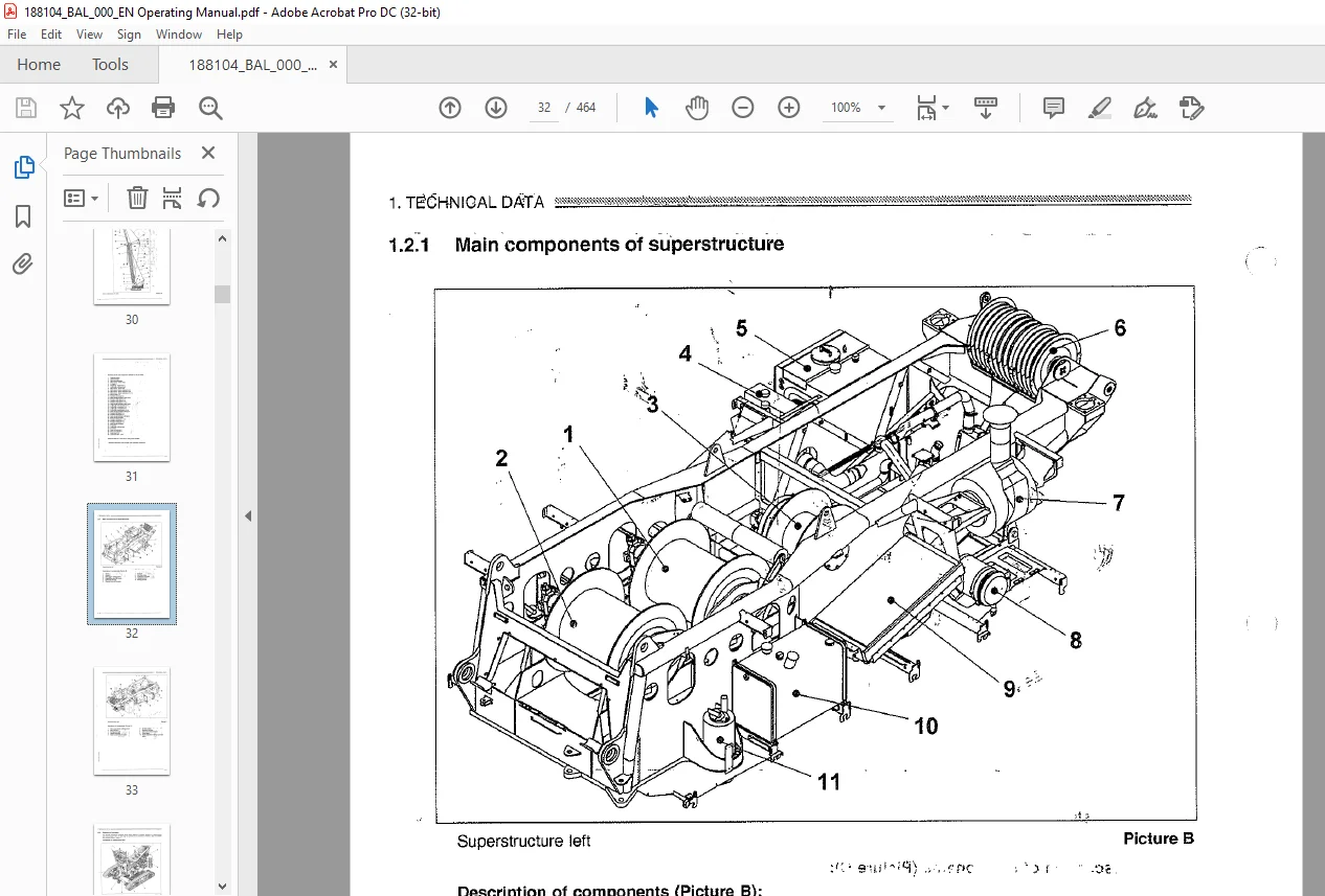
1.2.1 Main components of superstructure 1-4
12.2 Summary of cylinders 1-6
123 Main components undercarriage 1-9
1.3 OVERVIEW OF MAIN COMPONENTS OF THE POWER PACK 1-10
1.3.1 Power pack 1-10
1.3.2 Pump Components 1-11
1.4 TECHNICAL DATA 1-12
1.5 LOAD CHARTS 1-15
1.6 CONVERSION TABLE 1-16
1.7 TECHNICAL DATA FOR LR 1250 Litronic i-17
2. SAFETY DIRECTIVES 2-1
2.1 GENERAL INFORMATION -1
2.2 SAFETY DIRECTIVES FOR CRAWLER CRANES –
2.2 SAFETY DIRECTIVES FOR CRAWLER CRANES –
2.241 Appropriate application 2-2
2.22 Crane classification 2-2
2.2.3 Planning of operations 2-4
2.2.4 Demands on the crane operator 2-5
225 During operation 2-6
2.2.6 Travelling mode 2-7
22.7 Assembly 2-7
22.8 Maintenance 2-8
229 Crane out of function 2-9
2.3 MOST IMPORTANT SAFETY DECALS ON THE CRANE 2-10
2.341 Safety markers and their meaning 2-12
2.4 AVOIDING BRUISES AND BURNS 2-14
2.5 AVOIDING FIRE AND DANGER OF EXPLOSION 2-14
2.6 SAFETY INDICATIONS FOR START-UP 2-14
2.7 SAFETY INDICATIONS FOR ENGINE START-UP 2-15
2.8 INDICATIONS FOR SAFE OPERATION 2-15
2.9 SAFE TRANSPORTATION OF THE MACHINE 2-18
2.10 SAFE PARKING OF THE MACHINE 2-16
2.11 PROCEDURES FOR SAFE MAINTENANCE 2-16
2.12 HYDRAULIC HOSES AND BUCTS 2-17
2.13 SAFETY INDICATIONS FOR WORK ON THE EQUIPMENT 2-18
2.14 SAFETY INDICATIONS FOR PENDANTS 2-18
2.15 HAND SIGNALS 2-21
2.15.1 Area of application 2-21
2152 Purpose 2-21
INDEX mas
: 2.15.3 Handsignalssforcrane duty” – U : 2.21
A 2.15.4 Hand signals for working motions EE 2-22
2.16 SAFETY INDICATION FOR OPERATION cor – 2-25
2.16.1 Choice of position Tu – 2-25
2.16 SAFETY INDICATION FOR OPERATION cor – 2-25
2.16.1 Choice of position Tu – 2-25
i. 2.16.2 Slopes and diiches B oe 2-25
– 217 GROUND PRESSURE = Lo ’ 2-26
+8 . 2.17.1 Permissible ground pressures . 2-28
2.18 WIND FORCE. . : ’ 2-27
+8 . 2.17.1 Permissible ground pressures . 2-28
2.18 WIND FORCE. . : ’ 2-27
3. * CONTROLS AND INSTRUMENTATION – 3-1
£7 _ 31 GENERAL CL vy 3-1
N 3.1.1 Operation elements _ E 3-1
I. 3.2 OVERVIEW OF OPERATOR’S CAB . 3-2
” 33 LEFT CONTROL PANEL 3-4
34 RIGHT CONTROL PANEL 3-6
£7 _ 31 GENERAL CL vy 3-1
N 3.1.1 Operation elements _ E 3-1
I. 3.2 OVERVIEW OF OPERATOR’S CAB . 3-2
” 33 LEFT CONTROL PANEL 3-4
34 RIGHT CONTROL PANEL 3-6
35 OVERVIEW OF LCD- MONITOR . 3-10
3.5.1 indications } : co i 3-10
3.5.2 Description of main sections CL 3-11
3.53 Sequence of LCD- pages ) 3-11
38 __LOAD MOMENT LIMITATION ) – 3-12
3.861 _ General 3-12
3.6.2 __ Symbols and Indications ) 3-13
37 PAGE 1 “Crane operation mode” N ) : 3-14
3.7.1 _ Indications for Limit Switches B 3-18
38 PAGE 2 “Aggregate observations” 3-20
38 PAGE 2 “Aggregate observations” 3-20
3.8.1 Symbols for function buttons * Boyan : 3-22
. 3.8.2 Status indications » ot CART ge 3-23
3.9 PAGE 3 “Filter observations” ~ Jet 3-24
3.9.1 Symbols for function buttons 3-27
3.10 PAGE 4 “Error indications” Es 3-28
3.11 OPERATION MODES FOR THE LOAD MOMENT LIMITER 3-30
3.11.1 General ) { 3-30
3.11.2 Main operation modes of the Load Moment Limitation: ) 3-30
3.11.2 Main operation modes of the Load Moment Limitation: ) 3-30
3.11.3 Description of operation modes: : 3-30
3.11.4 Programming via function buttons: E 3-3
3.12 Main boom configuration page ] 3-34
3.4121 Adjusting and Programming of actual indications – 3-35
a 3.12.2 Description of function buttons ” 3-36
.3.13 PAGE 5 “Configuration page” : 3-38
3.14 LITRONIC SERVICE PANEL } – 3-41
3.15 FREEFALL SELECTION 3-43
3.15.1 General i a 3-43
3.15.2 Selection Freefall unsecured Sv 3-43
3.16 ROPE LENGTH MEASURMENT SYSTEM = 3-45
3.16.1 General ~ iB ‘ 3-45
8.100 (on) LWN – TD16/4/99
31 6.2 Programming the rope length measurment-system
3.17 ) WINDSHIELD WIPER 3-47
817.1 _Adusting infemmitanttime 3.47
817.1 _Adusting infemmitanttime 3.47
317.2 Windshield washer system a BB | 3-47
3.18 CABDOOR FIXATION EE 3-48
3.19 HEATER ) oo 3-49
319.1 Operation CL 3-49
3.19 HEATER ) oo 3-49
319.1 Operation CL 3-49
3182 } Heating operation oo Co 3-50
3.18.3 Cab ventilation 3-50
3.20 OPERATOR’S SEAT 3-51
3.20.1 Backrest diustment © 3-51
3.20.1 Backrest diustment © 3-51
N 3202 High and Inclination adjustment 3-51
3.20.3 Weight adjustment 3-51
3.20.3 Weight adjustment 3-51
3.20.4 Adjustment of compleie seat 3-51
OPERATION Bh B 4-1
41 PRE- STARTING INSPECTIONS 4-1
i 4.1.1 Engine oil level [a 4-1
OPERATION Bh B 4-1
41 PRE- STARTING INSPECTIONS 4-1
i 4.1.1 Engine oil level [a 4-1
© 412 Coolant level NB 4-1
4.1.3 Fuel system ) ) 4-2
) 414 Fuel Tank Level y 4-2
} 415 N Check gear oil level of splitter gearbox. ) 4-2
416 Checkolil level of hydraulic tank. ] 4-3
} 415 N Check gear oil level of splitter gearbox. ) 4-2
416 Checkolil level of hydraulic tank. ] 4-3
417 Sidevave es . ” 4-3
Co 41.8 Electrical system – 4-3
© 42 SAFETY INDICATIONS FOR START-UP 4-4
43 SAFETY INDICATIONS FOR ENGINE START-UP 4-4
43 SAFETY INDICATIONS FOR ENGINE START-UP 4-4
44 STARTING THE DIESELENGINE 4-5
4.4.4 Switch positions of starter key switch: 4-5
4.4.4 Switch positions of starter key switch: 4-5
) 442 Switching on electrical system 4-5
443 Starting procedure at outside temperatures below 0° 4-6
443 Starting procedure at outside temperatures below 0° 4-6
45 SAFE PARKING OF THE MACHINE 4-8
46 SHUTTING OFF THE CRANE 4-7
46.1 Shutting off diesel engine 4-7
46 SHUTTING OFF THE CRANE 4-7
46.1 Shutting off diesel engine 4-7
N 482 Emergency- Stop- Button 4-7
47 RPMADJUSTMENT 4-8
471 Ajust actual rpm of diesel engine 4-8
471 Ajust actual rpm of diesel engine 4-8
47.2 Constant rpm Adjustment 4-8
) 47.3 Minimum pm adjustment 4-8
474 i Working pm. adjustment 4-8
” 475 Rpm. setting via foot pedal 4-8
) 47.6 Electronic power regulation 4-8
474 i Working pm. adjustment 4-8
” 475 Rpm. setting via foot pedal 4-8
) 47.6 Electronic power regulation 4-8
48 INDICATIONS FOR SAFE OPERATION 4-9
49 OPERATIONS ) 4-10
49. Requirements 4-10
49. Requirements 4-10
4.9.2 Working position ) To iad 4-10
4.9.3 _ Llitronic control system 4-10
4.9.4 Operation mode 4-10
4.9.5 Recommendation for stability 4-11
4.8.6 Parallel operations 4-11
4.9.7 Load capacity table 4-11
4.9.8 Safety lever for control system 4-11
TRAVEL OPERATION 4-12
410.1 General 4-12
4.10.2 Crawler drive activation 4-12
4.10.3 Straight travel 4-12
4.10.4 Rotating on the spot 4-12
4.10.5 Rotating with one crawler 4-13
4.10.6 Hand control of the crawler 4-13
4.10.7 Fast speed function 4-13
OPERATION OF THE SWING GEAR 4-15
4.11.1 General use 4-15
4.11.2 Swing speed 4-15
4.11.3 Activation of the swing 4-15
4.11.4 Swing speed 4-16
FREE SWING SYSTEM 4-147
4.12.1 Free Swing System ON 4-17
4.12.2 Temporary activation of the free swing system 4-17
4.12.3 Function of Free Swing 4-19
4.12.4 Shut off Free Swing System 4-19
OPERATION QF THE MAIN BOOM WINCH 4-21
413.1 Adjustment of the main boom 4-21
413.2 Shut off functions for the main boom winch 4-21
4.13.3 Operation of the main boom winch with mounted luffing jib 4-23
OPERATION QF THE LUFFING JIB 4-25
4.14.1 Adjustment of the luffing jib 4-25
4.14.2 Selection of luffing jib winch during assembly operation mode 4-25
414.3 Adjusting the luffing jib during assemly 4-25
4.14.4 Adjustment during crane operation 4-25
4.14.5 Switch off functions 4-26
HOOK OPERATION 4-29
© 4151 Geneal 4-29
4.15.2 Reeving of the hoisting rope 4-29
4,15.3 Counterweight 4-29
4.15.4 Operation of the winch 4-29
4.15.5 Hoisting limit switch 4-31
4.15.6 Lower Limit switch 4-31
4.15.7 Load Moment Limiter 4-31
© 416 HOOK OPERATION WITH BOTH WINCHES 4-33
~ 416.2 Reeving of the hoisting rope 4-33
4.16.3 Counterweight 4-33
; B ) 4.16.4 Activation of winches 4-33
CoE ~ 4.16.5 Hoisting limit switch ily 4-34
’ 4.16.6 Lower Limit switch 4-34
_ 4.16.7 Load Moment Limitation 3 4-34
ro 4.17 FAST SPEED OPERATION FOR WINCH 1 OR WINCH 2 4-35
wl 3 417.1 General 4-35
K B 417.2 Function 4-35
T+ 418 FREEFALL OPERATION WINCH 1 +2* 4-36
4181 General 4-36
2 N 4.18.2 Freefall operation “secured” 4-37
ot 4.18.3 Freefall operation “unsecured” 4-37
LE 4.18.4 Activation of freefall function 4-38
ree 4.18.5 Operation during freefall 4-39
’ 4.18.6 Freefall operation “OFF” 4-39
_ B 418.7 Winch standstill monitoring 4-38
-+ 419 WINCH CONFIGURATION 4-41
R 4.19.1 Operations with main boom 4-41
4.19.2 Operation with luffing jib 4-41
4.18.3 Operation with Boom head runner 30 t 4-41
5. _._ LUBRICANTS AND SERVICE FLUIDS 5-1
¢ 5.1 GENERAL INFORMATION 5-1
52 LUBRICANTS AND SERVICE FLUIDS 5-2
5.3 CAPACITY CHART 5-12
54 FILTER AND V- BELTS 5-13
5.4.1 Engine – D 9408 TI-E A4 400 kW 5-13
54.2 Hydraulic system 5-13
5.4.3 V – belts 5-13
_ 5.5 GREASING CHART 5-15
_56 TABLE OF LUBRICANTS 5-17
6. MAINTENANCE 6-1
6.1 MAINTENANCE OVERVIEW 6-1
— – . 611 Welding work 6-
FR 6.2 DIESEL ENGINE
6.2.1 Check engine oil level
8.2.2 Changing engine oil
. .. 8.23 Changing the oil! filter cartridges
—.— 63 FUEL SYSTEM
IN 6.3.1 Arrangement of fuel system
ee 6.3.2 . ..Fueltank water separator
eo —.. 6.33… Draining water and sediments
6.3.4 Drain fuel tank en
8.3.5 Cleaning fuel tank 6-5
6.3.6 Fuel tank filling 6-5
__COOCLING SYSTEM 6-7
6.4.1 Check coolant level 6-7
6.4.2 Changing the coolant 6-7
6.4.3 Water filter coolant system 6-9
6.44 Adjusting V- belt tension 6-10
6.45 _ Changing V- belt 6-10
MEASURING DEVICE FOR V- BELT TENSION 6-11
DRY AIR FILTER 6-12
6.6.1 Arrangement 6-12
6.6.2 General 6-13
6.6.3 Cleaning the dry air filter 6-13
6.6.4 Dry cleaning 6-13
DISTRIBUTOR GEAR BOX 6-14
6.7.1 Checking gear oil level 6-14
6.7.2 Changing gear oil 6-15
6.7.3 Filling gear oil 6-15
B74 Recommendation for service 6-15
WINCH 1 +2 6-17
6.8.1 General 6-17
6.8.2 Gear oil change 6-17
6.8.3 Recommendation for service 6-17
.. B84 Cooling for Freefall lamella disc brake * 6-17
6.8.5 Wear control tooth profile shaft 6-17
6.8.6 Standstill monitoring 6-17
6.8.7 Guide pulley at Winch 1 6-17
MAIN BOOM WINCH 6-18
_ 6.9.1 General 6-19
6.9.2 Checking oil level 6-19
6.9.3 Change gear oil 6-19
6.9.4 Recommendation for service 6-19
6.8.5 Wear control tooth profile shaft 6-17
6.8.6 Standstill monitoring 6-17
6.8.7 Guide pulley at Winch 1 6-17
MAIN BOOM WINCH 6-18
_ 6.9.1 General 6-19
6.9.2 Checking oil level 6-19
6.9.3 Change gear oil 6-19
6.9.4 Recommendation for service 6-19
_ SWING GEAR 6-21
6.10.1 Checking oil level 6-21
6.10.2 Drain gear oil 6-21
6.10.3 Recommendation for service 6-21
6.10.4 Assembly of swing gear 6-22
CRAWLER GEAR 6-23
6.11.1 Gear 6-23
6.11.2 Check gear oil level 6-23
6.11.3 Changing the gear ail 6-23
6.11.4 Check crawler drive components 6-24
6.11.5 Recommendation for service 6-24
CRAWLER COMPONENTS 6-25
6.12.1 Tension of track shoes 6-25
8.100 {bn) LWN – TD16/4/99
6.12.2 Reduction track shoe tension 4 6-26
6.12.3 Idler wheels } 6-26
6.12.4 Fixation bofts – 6-26
) 6.12.5 Cleaning the crawlers N So 6-26
6.13 ROLLER BEARING SWING CONNECTION 6-27
643.1 Toothing . 6-27
6.13 ROLLER BEARING SWING CONNECTION 6-27
643.1 Toothing . 6-27
6.132 Fastening screws 6-27
6.13.3 Lubrication of bearing path of swing connection 6-27
6.13.4 Lubrication procedure – Es 6-27
6.13.5 Checking the hydraulical swing connection (Figure 22) 6-27
MAINTENANCE OF THE HYDRAULIC SYSTEM 6-29
6.14.1 Checking the hydraulic oil level 6-29
MAINTENANCE OF THE HYDRAULIC SYSTEM 6-29
6.14.1 Checking the hydraulic oil level 6-29
6.14.2 Maintenance intervals 6-29
6.14.3 Hydraulic tank drain unit 6-29
6.14.4 Complete filling of the hydraulic system i 6-30
6.14.5 Hydraulic suction pipe 6-30
3 6.14.6 Ventilation filter on the hydraulic tank 6-31
6.14.7 Repair works at the hydraulic system 6-31
6.14.7 Repair works at the hydraulic system 6-31
64 4.8 Special maintenance points 6-31
~ 6.149 Pressure fitter 6-32
] BN 6.14.10 Changing the return flow filter 6-34
8.15 WIRE ROPES 6-35
oo 6.15.1 Condition before installation 6-35
6.15.2 Installation 6-35
8.15 WIRE ROPES 6-35
oo 6.15.1 Condition before installation 6-35
6.15.2 Installation 6-35
6.153 Maintenance 6-35
6.15.4 Control of wire ropes 6-36
6155 Control works 6-36
6155 Control works 6-36
6.1 5.6 Life time 6-37
6.15.7 Kind and number of wire breaks 6-37
6.458 Position of wire breaks 6-37
6.15.9 Chronological occurence of wire breaks 6-37
6.15.10 Reduction of rope diameter during operation 6-37
6.1 5.1 1 Corrosion 6-37
– 6.15.12 Replacement of wire ropes due to wire breaks 6-38
61513 Abrasion 6-39
6.15.14 Deformations of wire rope 6-39
61513 Abrasion 6-39
6.15.14 Deformations of wire rope 6-39
© 6.15.15 Basket like deformation 6-40
6.15.16 Loop-like deformation 6-40
6.15.17 Loosening of single wires or strands 6-40
6.15.16 Loop-like deformation 6-40
6.15.17 Loosening of single wires or strands 6-40
6.1518 Knots 6-40
6.15.19 Contractions 6-41
6.15.20 Flattenings 6-41
6.15.21 Curl-like deformations 6 – 41
6.15.22 Nooses 6-41
6.15.23 Bends 6 – 41
[gl]
8.15.24 Lifetime of cables 6-42
_ 6.15.25 Cable suspension and cable endfastenings 6-42
6.16 CHECKING OF PENDANTS 6-43
_6.16.1 Pendants at the main boom 6-43
_6.16.1 Pendants at the main boom 6-43
6.16.2 Checking of pendants 6-44
6.16.3 Checking procedures 6-44
6.17 BOOM SECTIONS AND ROPE PULLIES 6-45
6.17.1 _ Boom intermediate sections 6-45
6.17.1 _ Boom intermediate sections 6-45
6.17.2_ Boom intermediate sections 6-45
6.17.3 Checking of pendants connection 6-45
_ 6.17.4 Rope pullies at basic machine 6-46
6.17.5 rope pullies at A- frame 6-46
6.17.5 rope pullies at A- frame 6-46
6.17.6 Boom limit switch 6-47
6.17.7 Main boom head 6-47
6.17.8 Hoist Imi switch * 6-47
6.17.8 Hook block 6-48
__ 617.10 Hookblock 1510 6-48
6.18 MAIN COUNTERWEIGHT 6-49
6.19 MAINTENANCE OF ELECTRICAL SYSTEM 6-51
6.19.1 General 6-51
6.19 MAINTENANCE OF ELECTRICAL SYSTEM 6-51
6.19.1 General 6-51
6.19.2 Wet cleaning 6-51
6.19.3 Liccon monitor 6-51
6.19.4 Rotary connection electric * 6-51
oo 6.18.5 Batteries 6-52
6.20 HEATING AND COOLING SYSTEM 6-53
6.21 HEATING AND VENTILATION 6-53
6.22 TRANSPORTING SLINGS 6-55
6.22.1 General 6-55
6.20 HEATING AND COOLING SYSTEM 6-53
6.21 HEATING AND VENTILATION 6-53
6.22 TRANSPORTING SLINGS 6-55
6.22.1 General 6-55
6.22.2 Wire rope attachment device 6 – 56
6.28 MAINTENANCE AND INSPECTION CHART 6-57
7. © ASSEMBLY AND DISASSEMBLY 7-1
’ 71 GENERAL INDICATIONS 7-1
7.14 Conditions 7-1
7. © ASSEMBLY AND DISASSEMBLY 7-1
’ 71 GENERAL INDICATIONS 7-1
7.14 Conditions 7-1
7.1.2 Maximum possible assembly lengths. 7-2
7.2 SEQUENCE OF ASSEMBLY PROCEDURE 7-4
— 7.21 Sequence of assembly procedures: 7-4
7.3 ERECTION MODE 7-5
7.3.1 General guidelines 7-5
— 7.21 Sequence of assembly procedures: 7-4
7.3 ERECTION MODE 7-5
7.3.1 General guidelines 7-5
7.32 Selection erection mode 7-5
7.3.3 Displays for erection mode 7-5
7.3.4 Selection bypass load moment limitation 7-6
7.3.5 Erection operation mode off 7-6
7.4 CRANE HANDLING IN ERECTION DUTY 7-7
7.4.1 Operating the main functions 7-7
7.4.1 Operating the main functions 7-7
7.142 Assembly
7.4.2 Operating the cylinders gL 7-7
TRANSPORT OF THE BASIC MACHINE wy ] 7-8
7.5.1 Transport position of basic machine: ) & IE 7-8
UNLOADING WITH AUXILIARY CRANE de sa 7-9
7.6.1 General guidelines ) . 7-9
782 Unloading procedure vo 7-10
POSITIONING OF OPERATOR’S CAB +- ~L 7-13
771 Generalguidelnes – ” 7-13
TRANSPORT OF THE BASIC MACHINE wy ] 7-8
7.5.1 Transport position of basic machine: ) & IE 7-8
UNLOADING WITH AUXILIARY CRANE de sa 7-9
7.6.1 General guidelines ) . 7-9
782 Unloading procedure vo 7-10
POSITIONING OF OPERATOR’S CAB +- ~L 7-13
771 Generalguidelnes – ” 7-13
__ 7.7.2 Conditions 7-18
7.7.3 Swinging out of operator cab 2 7-13
7.7.4 Swinging in of operator’s cab 7-14
7.7.3 Swinging out of operator cab 2 7-13
7.7.4 Swinging in of operator’s cab 7-14
A- FRAME POSITIONING 7-15
7.8.1 General guidelines 7-15
7.82 A- Frame positioning in erection mode 7-15
7.83 Positioning in crane duty 7-15
7.84 Erect A-frame 1 7-17
7.85 Lower A- Frame o 7-18
7.8.1 General guidelines 7-15
7.82 A- Frame positioning in erection mode 7-15
7.83 Positioning in crane duty 7-15
7.84 Erect A-frame 1 7-17
7.85 Lower A- Frame o 7-18
~ UNLOADING BY USING THE CYLINDER JACKS . , 7-19
7.9.1 General guidelines 7-19
7.9.2 Preparations . B 7-19
7.93 Positioning of cylinder jacks 7-21
MOUNTING OF THE CRAWLERS 0 7-23
7.10.1 General guidelines 7-23
7.10.2 Conditions 7-23
7.10.3 Safety notes for crawler assembly ° 7-23
7.104 Assembly of the first crawler 7-25
7.10.5 Assembly of the second crawler CL, 7-27
MOUNTING THE CARBODY COUNTERWEIGHT ONTO THE UNDERCARRIAGE 7-29
7.11.1 General guidelines 7-29
7.1 1.2 Assembly of the carbody counterweight 7-29
7.11.3 Assembly of platforms and ladders 7-30
ASSEMBLY OF THE MAIN COUNTERWEIGHT 7-3
7.12.1 General guidelines 7-3
7.12.2 Conditions 7-31
7.12.3 Unloading of the counterweight components 7-H
7.124 Assembly of the main counterweight 7-33
7.125 Assembly on the basic machine 7-35
ASSEMBLY OF THE MAIN BOOM 7-37
© 7.431 General guidelines 7-87
7.132 Pinning of the boom extensions 7-38
7.133 Pendants on main hoom 7-38
7.134 Mounting of pendants 7-39
ASSEMBLY MAIN BOOM FOOT SECTION 7-45
7.141 General guidelines 7-45
STAY SUPPORT CYLINDERS ON MAIN BOOM 7-49
__ 7.51 General guidelines 7-49
7.15.2 Mounting of the stay support cylinders 7-51
7.15.3 _ Refract stay support cylinders 7-52
ASSEMBLY OF THE MAIN BOOM 7-53
7.16.1 General guidelines 7-53
7.16.2 Preparations for the assembly 7-53
7.16.3 Assembly of main boom to basic machine 7-55
ERECTING THE MAIN BOOM 7-59
7.17.1 General guidelines 7-59
7.17.2 Erecting the pre-assembled main boom 7-61
ASSEMBLY OF THE LUFFING JIB 7-63
7.18.1 General guidelines 7-63
7.18.2 Connecting pin on the jib extensions 7-64
7.18.3 Connecting pin on jib foot section 7-64
7.18.4 Pin connections of pendants 7-64
7.185 Assembly of the lufiing jib 7-65
___ 7.186 Pendants for the luffing jib 7-67
_ 7.187 Assembiy of the pendants 7-68
ASSEMBLY OF THE LUFFING J!B 7-73
7.19.1 – General guidelines 7-73
7.19.2 Preparations 7-73
7.19.3 Conditions for the assembly 7-75
7.19.4 Mounting of the luffing jib 7-75
7.18.5 Changing the position of the rope protectors 7-75
7.19.6 Assembling the coupler attachment device 7-76
ERECTING THE LUFFING JIB 7-79
7.20.1 General guidelines 7-79
7.20.2 _ Conditions for the erection: 7-79
7.20.3 Operation by use of control levers 7-79
7.20.4 Erecting the luffing jib 7-81
AUXILIARY JIB30 to” 7-83
7.21.1 General guidelines Z 7-83
7.212 Assembly © 7-83
7.21.3 Rope rn 7-84
ERECTING WITH AUXILIARY ERECTING DEVICE * 7-85
7.221 General guidelines 7-85
7.22.2 Mounting of erecting device 7-87
ERECTING WITH AUXILIARY CRANE 7-89
7.23.1 General guide lines 7-89
E 7.232 Erecting the main boom – 7-89
7.23.3 Required hoisting capacity and hoisting height for the main boom 7-90
7.23.4 Erection of main boom 7-91
7.23.5 Required capacity and hoisting heights for the luffing jib _ 7-81
DISASSEMBLY 7-95
7.23.3 Required hoisting capacity and hoisting height for the main boom 7-90
7.23.4 Erection of main boom 7-91
7.23.5 Required capacity and hoisting heights for the luffing jib _ 7-81
DISASSEMBLY 7-95
5.100 (bn) LWN – TD16/4/89
~ 7.241 General guidelines « “v od 7-85
el nN 7.24.2 Putting down the boom ) 7-96
7.25 SEQUENCE WHEN LAYING DOWN dae Cul 7-98
7.26 LAYING DOWN OF MAIN BOOM nr 7-99
> 3 7.261 General guidelines 7-99
i 7.26.2 Laying down main boom ot, 7-101
~ _ 7.27 LAYING DOWN THE LUFFING JIB 7-103
Se 7.27.1 General guidelines 3 7-103
N 7.27.2 Function assignment of control levers in erecting duty = – 7-103
N 7.27.3 Condition for laying down 7-105
Co oo 7.27.4 Laying down the luffing jib . 7-105
de 7.28 DISASSEMBLY OF LUFFING JIB aE Li 7-107
7.29 DISASSEMLY OF MAIN BOOM FOOT SECTION – 7-111
v _ 7.28.1 General guidelines 7-111
So 7.282 Disconnecting from basic maghing 7-113
7. 30 DISMOUNTING OF MAIN COUNTERWEIGHT 7-115
N ~ 7.80.1 General guidelines 7-115
i: 7.30.2 Condition for the dismounting 7-115
( 7.30.3 Dismounting of main counterweight from basic machine: 7-117
7.304 Disassemble the counterweight components ry 7-118
_ 7.31 DISASSEMBLY OF PLATFORMS AND OF THE CARBODY COUNTERWEIGHT 7-119
i. oo 7.31.1 Disassembly of platforms and access ladders 7-119
ut 7.31.2 Disassembly of carbody counterweight ou 7-119
‘ 7. a2 Dismounting the crawlers 7-121
7.32.1 General guidelines 7-121
7.322 Dismounting of the first crawler 7-123
7.33 LOADING WITH JACKUP CYLINDERS 7-125
3 7.3341 General guidelines 7-125
7.34 LOADING WITH AUXILIARY CRANE 7-129
__ 7.341 General guidelines 7-129
B 7.342 Loading with slings 7-130
8. INSTRUCTIONS ON CHANGING THE CABLES -1
8.0.1 Instructions for handling wire ropes –
. 8.02 Wire rope mounting –
_8.1 MAIN BOOM WINCH ROPE –
oo… 8141 Reeving diagram of main boom winch –
2 8.2 WIRE ROPE REPLACEMENT AT THE MAIN BOOM WINCH –
a 821 Preparations for replacing the wire rope –
822 Remooving the old wire rope –
8.2.3 Arrangement of main hoom winch –
. 8.02 Wire rope mounting –
_8.1 MAIN BOOM WINCH ROPE –
oo… 8141 Reeving diagram of main boom winch –
2 8.2 WIRE ROPE REPLACEMENT AT THE MAIN BOOM WINCH –
a 821 Preparations for replacing the wire rope –
822 Remooving the old wire rope –
8.2.3 Arrangement of main hoom winch –
: 8.3 Replacement of luffing jib wire rope
) 831 General
= 8.3.2 Reeving diagram for luffing jib wire rope –
8.3.3 _ Mounting luffing jib wire rope 8-9
8.3.3 _ Mounting luffing jib wire rope 8-9
INDEX som ns inns
SRA RRR
8.4 REPLACEMENT EQR WIRE.ROPES AT WINGH 1 ARD 2%. ¢ ERS 8-11
8.4.1 General . nn A 8-11
. 85. . Reeving diagrams for main boom operation . x a 8-12
. 8.5.1 Reeving diagram for hook operatiofy with Winch 1 ) 8-12
…86 Reeving diagram for luffing jip operation with Winch 1 = ol 8-16
9. TIGHTENING TORQUES 9-1
9.1 TIGHTENING TORQUES FOR SCREWS WITH STANDARD METRIC THREAD 9-2
9.1 TIGHTENING TORQUES FOR SCREWS WITH STANDARD METRIC THREAD 9-2
9.2 TIGHTENING TORQUES FOR SCREWS WITH FINE METRIC THREAD
10. SPECIAL ATTACHMENTS / OPTIONS 10-1
10.1 HOISTING LIMIT SWITCH 10-3
10.2 BACK UP CONTROL SYSTEM 10-5
10.1 HOISTING LIMIT SWITCH 10-3
10.2 BACK UP CONTROL SYSTEM 10-5
10.2.1 General 10-5
10.2.2 Function 10-5
10.2.3 Operation via control panel 10-6
10.3 REEVING WINCH 10-7
10.3.1 Arrangement of compontns 10-7
10.3.2 Description of components: 10-7
10.3.3 ROPE REEVING 10-8
10.3.4 Technical description 10-8
10.3.5 Technical data: 10-8
10.3.6 Operation 10-8
10.3.7 Switching off reeving winch 10-9
10.3.8 Maintenance of reeving winch 10-10
10.3.3 Gear oil change 10-10
10.4 ADDITIONAL GUY ROPES 10-11
104.1 General 10-11
10.4.2 Connection of guy ropes 10-11
10.4.3 Assembly of guy ropes 10-13
10.5 GUY ROPES FOR LUFFING JIB 10-15
10.5.1 General 10-15
10.5.2 Assembly of guy ropes 10-15
10.5.3 Assembly of guy ropes 10-17
10.6 AIR CONDITIONING SYSTEM 10-19
10.6.1 Technical Data 10-18
10.6.2 Reirigerant receiver 10-19
10.6.3 Major components 10-20
10.6.4 General safety information 10-21
10.6.5 Handling coolants 10-21
10.6.6 Cooling systems 10-21
10.6.7 Operation of the air conditioning system 10-23
10.6.8 Maintenance of the air conditioning system 10-25
10.7 ADDITIONAL PULLEY BLOCK 10-27
10.7.1 General 10-27
Assembly of pullgy block, «y+.
10.8 EXTERNAL HORN
10.9 GREASING SYSTEM UNDERCARRIAGE
General
Function d escription
Contact us: [email protected]
PLEASE NOTE:
- This is not a physical manual but a digital manual – meaning no physical copy will be couriered to you. The manual can be yours in the next 2 mins as once you make the payment, you will be directed to the download page IMMEDIATELY.
- This is the same manual used by the dealers inorder to diagnose your vehicle of its faults.
- Require some other service manual or have any queries: please WRITE to us at [email protected]
S.V