Trusted Business
Verified & Licensed
Virus Free Files
100% Safe Downloads
Secure Payment
SSL Protected
Instant Delivery
Available Immediately
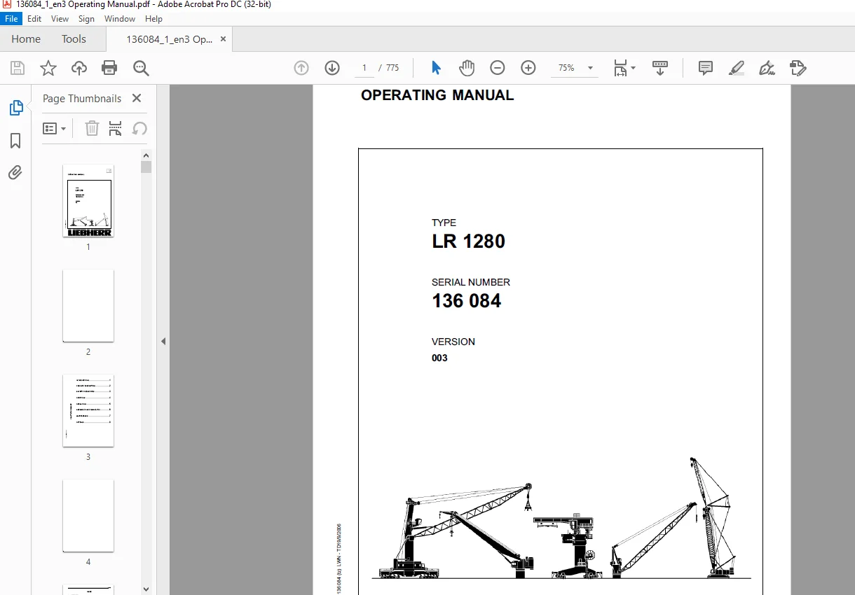
Liebherr Crawler Crane LR 1280 OPERATING MANUAL 136084 – PDF DOWNLOAD
$33.95
Liebherr Crawler Crane LR 1280 OPERATING MANUAL 136084 – PDF DOWNLOAD
Instant PDF Download
Available immediately
Save to Your Device
Download & keep forever
Antivirus Scanned
100% virus-free
Trusted Worldwide
175,000+ customers
Description
Liebherr Crawler Crane LR 1280 OPERATING MANUAL 136084 – PDF DOWNLOAD
FILE DETAILS:
Liebherr Crawler Crane LR 1280 OPERATING MANUAL 136084 – PDF DOWNLOAD
Language : English
Pages : 775
Downloadable : Yes
File Type : PDF
DESCRIPTION:
Liebherr Crawler Crane LR 1280 OPERATING MANUAL 136084 – PDF DOWNLOAD
INTRODUCTION
1.1 Foreword
We are pleased to present another top-flight model in our crawler crane series . As the result of the modularization of our crawler crane series, a wide range of boom configurations can be implemented around this basic machine. This provides you with optimal utilization of the machine across a wide variety of applications
About us
The name Liebherr doesn’t just stand for products and services. It has become a byword for ideas and innovations. For progress which has proved its worth in the marketplace. We constantly strive to extend and improve our diverse range of products and services. This requires ongoing cooperation and sharing of experience with our customers and business partners throughout the world. We are therefore grateful for any ideas and suggestions for improvements.
SAFETY PRECAUTIONS
3.1 General
3.1 General
Your safety – as machine operator or maintenance technician – is of the utmost priority. Many situations, problems or malfunctions occurring on the machine can pose a serious risk to safety if you are not fully familiar with the actions to be taken to prevent and avert possible dangers.
This chapter
– establishes what is meant by appropriate use of the machine,
– contains generally applicable information on safety and safety precautions,
– explains the meaning of the symbols and pictograms used in this operating manual and in the
signs on the machine,
– gives information about the necessary protective equipment and which requirements apply to
operating and maintenance personnel,
– shows the location of the safety and monitoring devices on the machine,
– gives information concerning dangers and other risks which can also occur even when the
machine is being operated properly
– establishes what is meant by appropriate use of the machine,
– contains generally applicable information on safety and safety precautions,
– explains the meaning of the symbols and pictograms used in this operating manual and in the
signs on the machine,
– gives information about the necessary protective equipment and which requirements apply to
operating and maintenance personnel,
– shows the location of the safety and monitoring devices on the machine,
– gives information concerning dangers and other risks which can also occur even when the
machine is being operated properly
Special handling and situation-specific notes on safety are specified where relevant in the following chapters of this operating manual and in further sections of the documentation included on delivery.
IMAGES PREVIEW OF THE MANUAL:
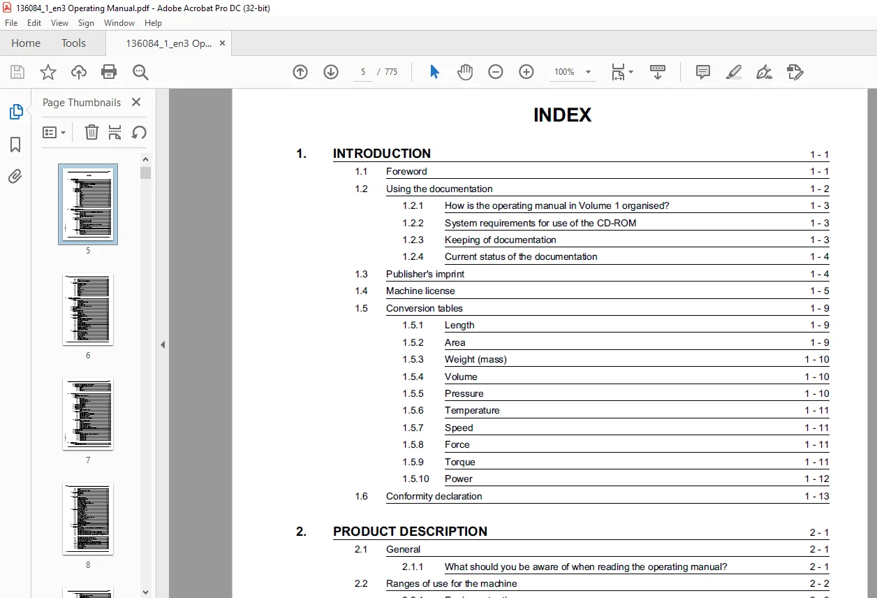
TABLE OF CONTENTS:
Liebherr Crawler Crane LR 1280 OPERATING MANUAL 136084 – PDF DOWNLOAD
1. INTRODUCTION............................................................. 19
	1.1 Foreword............................................................ 19
	1.2 Using the documentation............................................. 20
		1.2.1 How is the operating manual in Volume 1 organised?............ 21
		1.2.2 System requirements for use of the CD-ROM..................... 21
		1.2.3 Keeping of documentation...................................... 21
		1.2.4 Current status of the documentation........................... 22
	1.3 Publisher's imprint................................................. 22
	1.4 Machine license..................................................... 23
	1.5 Conversion tables................................................... 27
		1.5.1 Length........................................................ 27
		1.5.2 Area.......................................................... 27
		1.5.3 Weight (mass)................................................. 28
		1.5.4 Volume........................................................ 28
		1.5.5 Pressure...................................................... 28
		1.5.6 Temperature................................................... 29
		1.5.7 Speed......................................................... 29
		1.5.8 Force......................................................... 29
		1.5.9 Torque........................................................ 29
		1.5.10 Power........................................................ 30
	1.6 Conformity declaration.............................................. 31
2. PRODUCT DESCRIPTION...................................................... 35
	2.1 General............................................................. 35
		2.1.1 What should you be aware of when reading the operating man.... 35
	2.2 Ranges of use for the machine....................................... 36
		2.2.1 Equipment rating.............................................. 37
		2.2.2 Explanatory notes on the equipment rating..................... 38
	2.3 Machine overview.................................................... 39
	2.4 Boom................................................................ 40
		2.4.1 Information on boom designations.............................. 40
		2.4.2 Main boom with 2220-boom head................................. 42
		2.4.3 Tip boom*..................................................... 58
		2.4.4 Main boom with 2220/1916 reducing piece and 1916 boom head.... 62
		2.4.5 Fixed jib on 2220-boom head................................... 71
		2.4.6 1916- luffing jib on 2220-boom head........................... 81
		2.4.7 Tip boom * for jib head with system no. 1916.21............... 94
	2.5 Basic machine....................................................... 96
		2.5.1 Upper carriage................................................ 97
		2.5.2 Central power unit............................................100
		2.5.3 Lower carriage................................................101
		2.5.4 Hydraulic chain tensioner.....................................103
		2.5.5 Ballast.......................................................104
		2.5.6 Overview of the hydraulic cylinders...........................107
	2.6 Technical data......................................................108
		2.6.1 Dimensions and weights........................................108
		2.6.2 Operating conditions..........................................113
		2.6.3 Emissions.....................................................113
		2.6.4 Engine........................................................114
		2.6.5 Hydraulic system..............................................115
		2.6.6 Winches.......................................................115
		2.6.7 Slewing gear..................................................117
		2.6.8 Travel gear...................................................117
		2.6.9 Control.......................................................121
3. SAFETY PRECAUTIONS.......................................................125
	3.1 General.............................................................125
		3.1.1 Appropriate use...............................................126
		3.1.2 Examples of inappropriate use.................................127
		3.1.3 Danger symbols................................................128
		3.1.4 Areas of responsibility.......................................129
	3.2 Personal attributes required of the machine operator................130
	3.3 Personal protective wear............................................131
	3.4 Work area...........................................................132
	3.5 Safety and monitoring devices.......................................133
		3.5.1 Safety devices................................................133
		3.5.2 Monitoring devices............................................135
	3.6 Set of name plates on the machine...................................136
		3.6.1 Meaning of the safety signs...................................141
	3.7 Machine-specific dangers............................................144
		3.7.1 Injuries resulting from operating machinery...................144
		3.7.2 Injuries due to hydraulic energy..............................146
		3.7.3 Risk of burns.................................................147
		3.7.4 Risk of chemical burns........................................148
		3.7.5 Fire and explosion hazards....................................149
		3.7.6 Risk of poisoning and asphyxiation............................152
		3.7.7 Safety Precaution for using refrigerants......................153
		3.7.8 Electromagnetic influences....................................155
		3.7.9 Endangering the environment...................................156
	3.8 Additional dangers..................................................157
		3.8.1 Effect of winds and storms....................................157
		3.8.2 Ground conditions on the site.................................162
		3.8.3 Snow and ice loads............................................163
		3.8.4 Lightning strikes.............................................164
		3.8.5 Overhead power lines..........................................165
		3.8.6 Underground pipes and cables..................................174
	3.9 Safety precautions for the machine operator.........................179
	3.10 Safety precautions for maintenance and repair personnel............179
	3.11 Safety precautions for construction site personnel.................180
		3.11.1 Signalman....................................................180
		3.11.2 Rigger.......................................................182
		3.11.3 Hand signals.................................................182
4. CONTROLS.................................................................193
	4.1 General.............................................................193
	4.2 Control elements on the lower carriage..............................194
	4.3 Cab.................................................................195
		4.3.1 Cab overview..................................................195
		4.3.2 Control stand overview........................................197
		4.3.3 Overhead view of control stand................................199
		4.3.4 Joysticks and pedals..........................................202
	4.4 Left-hand control panel (X11).......................................203
	4.5 Left-hand control panel (X12).......................................206
	4.6 Right-hand control panel (X23)......................................208
	4.7 Litronic service panel..............................................211
		4.7.1 Emergency shut-down switch....................................213
	4.8 Overview of screens.................................................214
		4.8.1 Main areas of the screen......................................214
		4.8.2 Description of the main areas of the screen...................215
		4.8.3 Description of the LCD display:...............................216
		4.8.4 Overview of mode screens......................................217
		4.8.5 Function symbols and display fields...........................219
	4.9 Set-up screens......................................................221
		4.9.1 Explanations of set-up screens................................221
		4.9.2 Main boom.....................................................222
		4.9.3 Main boom with reducing piece.................................224
		4.9.4 Main boom with fixed fly jib..................................226
		4.9.5 Main boom with adjustable fly jib.............................228
		4.9.6 Main boom with adjustable fly jib head and Midfall............229
	4.10 Power operation....................................................231
	4.11 Power unit monitoring..............................................238
	4.12 Fault displays.....................................................241
	4.13 Load capacity chart................................................243
		4.13.1 Enter load capacity calculation in set-up modes 4 and 5......244
		4.13.2 Load capacity chart Set-up 4 - Load location 1...............244
		4.13.3 Load capacity chart Set-up 4 - Load location 2...............244
		4.13.4 Load capacity chart Set-up 5 - Load location 1...............245
		4.13.5 Load capacity chart Set-up 5 - Load location 3...............245
5. OPERATION................................................................249
	5.1 Safe working with the machine.......................................249
		5.1.1 Use of emergency shut-down switch.............................250
		5.1.2 Hooter........................................................250
		5.1.3 Actuate safety lever (access lever)...........................251
	5.2 Checks before daily operation.......................................252
		5.2.1 Tour of inspection............................................252
		5.2.2 Checks........................................................252
	5.3 Daily start up......................................................254
		5.3.1 Switching on the ignition.....................................254
		5.3.2 Confirming the existing set-up................................254
		5.3.3 Checking the fuel level.......................................255
		5.3.4 Refueling the machine with a tanker...........................255
		5.3.5 Refueling the machine from a refueling pump...................256
		5.3.6 Select operating modes........................................259
		5.3.7 Starting the diesel engine....................................259
		5.3.8 Adjusting the engine speed....................................260
	5.4 Machine operation - main functions..................................262
		5.4.1 Checks/activities on start-up.................................263
		5.4.2 Moving the machine............................................264
		5.4.3 Travel gear overdrive.........................................267
		5.4.4 Slewing the superstructure....................................268
		5.4.5 Adjusting the main boom.......................................271
		5.4.6 Adjusting the main boom or the adjustable fly jib.............272
		5.4.7 Operating the hoisting winches................................274
		5.4.8 Hoisting limit switch.........................................277
		5.4.9 Hydraulic cab inclination.....................................278
		5.4.10 Electronic load moment limiter (LML).........................279
	5.5 Power operation.....................................................282
		5.5.1 Load pick-up equipment........................................282
	5.6 load moment limiter (LML)...........................................283
		5.6.1 General information regarding boom head, load position and....283
		5.6.2 Programming LML...............................................285
		5.6.3 Load on tip jib* (set-up 1 with head 2).......................290
		5.6.4 Load on the main boom with the tip boom* fitted (Set-up 1 ....291
		5.6.5 Load on the main boom head with fixed fly jib fitted (Set-....293
		5.6.6 Load on the main boom head with adjustable fly jib fitted ....294
		5.6.7 Load on tip boom* attached to fly jib head (set-up 4).........295
		5.6.8 Load on fly jib head with tip boom* attached (set-up 4).......296
		5.6.9 Load on midfall (set-up 5, load position 3)...................297
		5.6.10 Load on fly jib head with midfall attached (set-up 5, loa....298
		5.6.11 Twin hook operation..........................................299
		5.6.12 Combined twin hook operation with main boom head and fly ....305
		5.6.13 Free-fall operation*.........................................308
		5.6.14 Winch synchronization*.......................................314
		5.6.15 Grapple control*.............................................315
	5.7 Rope length metering*...............................................317
		5.7.1 General.......................................................317
		5.7.2 Displays in the power operation screen........................317
		5.7.3 Programming rope length.......................................317
	5.8 Ground pressure gauge*..............................................319
	5.9 Outreach limitation*................................................320
		5.9.1 Adjusting the outreach limitation*............................321
		5.9.2 Check outreach limitation*....................................321
	5.10 Slewing gear limitation*...........................................322
		5.10.1 Setting slewing gear limitation*.............................323
		5.10.2 Check slewing gear limitation*...............................325
		5.10.3 Cancel slewing gear limitation*..............................326
	5.11 Blocked crawlers*..................................................327
		5.11.1 Leveling out the crawler position............................328
		5.11.2 Support plates required......................................328
		5.11.3 Positioning of the support plates............................329
		5.11.4 Driving onto the support plates..............................329
		5.11.5 Selecting "Blocked Crawlers*" mode...........................330
		5.11.6 Working in "Blocked Crawlers*" mode..........................330
		5.11.7 Resetting the load capacity display to zero (taring).........331
	5.12 Operating the machine - auxiliary func- tions......................332
		5.12.1 Driver's seat................................................332
		5.12.2 LCD screen adjustments.......................................333
		5.12.3 Windshield wiper.............................................334
		5.12.4 Heating and air-conditioning system*.........................336
		5.12.5 Lighting.....................................................338
		5.12.6 Radio........................................................339
		5.12.7 Ashtray......................................................340
		5.12.8 Cigarette lighter and socket in the cab......................340
	5.13 Shutting the machine down..........................................341
		5.13.1 Boom park position...........................................341
		5.13.2 Setting down the boom........................................342
		5.13.3 Shutting down the diesel engine..............................343
		5.13.4 Park position of the ignition starter switch.................344
		5.13.5 Checks before leaving the machine............................345
6. ASSEMBLY AND DISMANTLING.................................................349
	6.1 General.............................................................349
	6.2 Operational planning................................................350
		6.2.1 Defining the set-up...........................................351
		6.2.2 Assemble and prepare the transport equipment..................351
		6.2.3 Required hoisting rope length.................................352
	6.3 Safety precautions for assembly, dismantling and conversion.........353
		6.3.1 Requirements for the erecting team............................353
		6.3.2 Requirements for the site.....................................353
		6.3.3 Rules for executing the work..................................354
	6.4 Information on set-up mode..........................................355
		6.4.1 Operation in set-up mode......................................355
	6.5 Unloading and erecting the basic machine............................358
		6.5.1 Requirements..................................................358
		6.5.2 Summary of assembly stages....................................358
		6.5.3 Preparing for set-up mode.....................................362
		6.5.4 Swivelling the cab to the working position....................363
		6.5.5 Starting set-up mode..........................................365
		6.5.6 Lowering A-frame 1 to the unloading position..................367
		6.5.7 Unloading the basic machine...................................368
		6.5.8 Preparing the basic machine as a mounting crane...............377
		6.5.9 Attaching the crawler carrier.................................379
		6.5.10 Attaching the central counterweight..........................393
		6.5.11 Assembling the rear counterweight............................398
		6.5.12 Connecting the cable remote control for rear counterweigh....409
		6.5.13 Mounting and bolting the rear counterweight..................410
		6.5.14 Bolting the rear counterweight...............................414
	6.6 Assembly of main boom...............................................417
		6.6.1 Requirements..................................................417
		6.6.2 Overview of assembly stages...................................417
		6.6.3 Unload and position the main boom head........................418
		6.6.4 Unload and position the main boom intermediate pieces.........418
		6.6.5 Assembly of the main boom.....................................419
		6.6.6 Assemble main boom anchoring rods.............................420
		6.6.7 Intermediate tensioners on the main boom......................424
		6.6.8 Arrangement of rope guide*....................................428
		6.6.9 Position the load hook........................................430
	6.7 Attaching the main boom pivot piece.................................431
		6.7.1 General.......................................................431
		6.7.2 Attach main boom pivot piece to superstructure................432
		6.7.3 Connecting the multicoupling on the superstructure............435
	6.8 Attachment of main boom.............................................436
		6.8.1 General.......................................................436
		6.8.2 Preparations for attachment...................................436
		6.8.3 Attachment of main boom.......................................439
		6.8.4 Preparing connection of electrical plugs to the upper carr....442
		6.8.5 Connect the electrics to the upper carriage...................443
		6.8.6 Connect the electrics to the main boom head...................444
		6.8.7 Mounting and connecting the anemometer........................445
		6.8.8 Luffing the hoisting rope.....................................446
		6.8.9 Choosing the correct load hook................................451
		6.8.10 Rope reeving plans...........................................454
		6.8.11 Hoisting limit switch........................................465
		6.8.12 Erecting the main boom.......................................467
		6.8.13 Erecting procedure...........................................470
		6.8.14 Erectability of the 2220 main boom...........................471
		6.8.15 Canceling set-up mode........................................472
	6.9 Attachment of tip boom* to the 2220-boom head.......................473
		6.9.1 Requirements..................................................473
		6.9.2 Position the tip boom* in front of the 2220-boom head.........474
		6.9.3 Bolt the tip boom* to the 2220-boom head......................474
		6.9.4 Mount the hoisting limit switch on the tip boom*..............478
	6.10 Assembly of main boom with reducing piece..........................480
		6.10.1 Requirements.................................................480
		6.10.2 Overview of assembly stages..................................480
		6.10.3 Unloading and positioning the main boom with reducing pie....480
		6.10.4 Assemble main boom with reduction............................483
		6.10.5 Assembling the anchoring rods................................485
		6.10.6 Intermediate tensioners on main boom with 2220/1916 reduc....489
		6.10.7 Further procedure............................................492
		6.10.8 Rope reeving plans...........................................492
		6.10.9 Erectability of main boom with 2220/1916 reducing piece......495
		6.10.10 Ending set-up mode..........................................496
	6.11 Assembling the main boom with fixed jib............................497
		6.11.1 Requirements.................................................497
		6.11.2 Overview of assembly stages..................................499
		6.11.3 Unload and position the main boom head.......................500
		6.11.4 Attach the jib pivot piece...................................501
		6.11.5 Assemble the jib.............................................502
		6.11.6 Assembling the jib anchoring rods............................504
		6.11.7 Assembly of the main boom....................................505
		6.11.8 Completing assembly of the boom..............................505
		6.11.9 Attaching coupling links to the main boom....................506
		6.11.10 Attach the tensioning rods to the coupling links............507
		6.11.11 Erecting A-frame 2..........................................508
		6.11.12 Attaching the tensioning rods to the crossbar...............509
		6.11.13 Position the jib pivot piece................................510
		6.11.14 Connecting the electrics....................................511
		6.11.15 Reeving the load hook.......................................513
		6.11.16 Mount the hoisting limit switch weight......................515
		6.11.17 Erecting the main boom with fixed jib.......................517
		6.11.18 Erecting procedure..........................................517
		6.11.19 Erectability with fixed fly jib.............................521
	6.12 Assembly of main boom with adjustable jib..........................522
		6.12.1 Requirements.................................................522
		6.12.2 Mounting instructions........................................522
		6.12.3 Overview of assembly stages..................................523
		6.12.4 Unload and position the 2220-boom head.......................525
		6.12.5 Attaching the jib pivot piece................................526
		6.12.6 Assembling the jib...........................................528
		6.12.7 Assembling the jib anchoring rods............................529
		6.12.8 Intermediate tensioners on the jib...........................530
		6.12.9 Attaching the jib head.......................................533
		6.12.10 Attach the tip boom* to the jib head........................534
		6.12.11 Assembling the main boom....................................535
		6.12.12 Mount the main boom anchoring rods and jib tensioning ro....536
		6.12.13 Completing preparations on the boom.........................537
		6.12.14 Attach the main boom pivot piece to the basic machine.......537
		6.12.15 Attaching the main boom to the main boom pivot piece........538
		6.12.16 Preparing the hoisting rope as a mounting aid...............540
		6.12.17 Reeving the jib luffing rope................................541
		6.12.18 Erecting A-frames 2 and 3...................................544
		6.12.19 Connecting the jib pivot piece to A-frame 3.................546
		6.12.20 Bolting the jib tensioning rods to the basic rope of A-f....548
		6.12.21 Attaching the jib to the jib pivot piece....................550
		6.12.22 Bolting the jib anchoring rods of the jib and A-frame 3 ....552
		6.12.23 Luffing the hoisting rope(s) on the jib.....................554
		6.12.24 Reeving the load hook on the 2220-boom head.................554
		6.12.25 Connecting the electrics....................................555
		6.12.26 Mounting the hoisting limit switch on the 2220-boom head....556
		6.12.27 Raising the main boom with adjustable jib...................557
		6.12.28 Reeving the load hook on the jib head and tip boom*.........561
		6.12.29 Mounting the hoisting limit switch on the jib head and t....564
		6.12.30 Erecting the main boom and jib..............................565
		6.12.31 Erectability with adjustable fly jib........................567
	6.13 Time-saving conversion of the main boom............................568
	6.14 Dismantling the main boom with adjustable jib......................573
		6.14.1 Requirements.................................................573
		6.14.2 Overview of dismantling stages...............................574
		6.14.3 Preparations for dismantling in crane mode...................574
		6.14.4 Activate set-up mode.........................................574
		6.14.5 Setting down the load hook...................................575
		6.14.6 Lowering the jib.............................................575
		6.14.7 Unreeving the hoisting rope on the jib head..................577
		6.14.8 Lowering the jib and main boom...............................578
		6.14.9 Retracting the hoisting rope(s)..............................579
		6.14.10 Disconnecting the electrics.................................580
		6.14.11 Connect jib pivot piece to A-frame 3........................582
		6.14.12 Detaching the boom pivot piece from the jib.................583
		6.14.13 Move A-frames 2 and 3 towards the rear......................584
		6.14.14 Lower A-frames 2 and 3......................................585
		6.14.15 Pulling out the jib luffing rope............................588
		6.14.16 Retracting the tilting-back cylinders.......................588
		6.14.17 Separating the main boom anchoring rods from the basic r....589
		6.14.18 Detaching the mounting cylinder from the basic rope on A....589
		6.14.19 Unbolt the main boom pivot piece from the main boom.........589
		6.14.20 Detaching the main boom pivot piece from the upper carri....590
		6.14.21 Preparing the mounting crane................................590
		6.14.22 Dismantling the jib pivot piece.............................590
		6.14.23 Detaching the tip boom* from the jib head...................591
		6.14.24 Dismembering the main boom and jib..........................592
		6.14.25 Loading up the equipment....................................593
	6.15 Dismantling the main boom with fixed jib...........................594
		6.15.1 Requirements.................................................594
		6.15.2 Overview of dismantling stages...............................595
		6.15.3 Preparations for crane operation.............................596
		6.15.4 Activate set-up mode.........................................596
		6.15.5 Setting down the main boom with fixed jib....................597
		6.15.6 Lowering the main boom with fixed jib attached...............599
		6.15.7 Detaching the anemometer.....................................601
		6.15.8 Disconnecting the electrics..................................602
		6.15.9 Dismantling the jib pivot piece..............................604
		6.15.10 Dismantling the main boom and the main boom pivot piece.....606
		6.15.11 Dismembering the jib........................................606
		6.15.12 Dismantling the jib pivot piece.............................606
	6.16 Dismantling the main boom with reduction...........................608
	6.17 Dismantling the tip boom* on the main boom head....................608
	6.18 Dismantling the main boom..........................................608
		6.18.1 Requirements.................................................608
		6.18.2 Overview of dismantling stages...............................609
		6.18.3 Preparations for crane operation.............................610
		6.18.4 Activate set-up mode.........................................611
		6.18.5 Laying down the main boom....................................611
		6.18.6 Laying down procedure........................................613
		6.18.7 Laying down procedure with tip boom*.........................614
		6.18.8 Dismantling the tip boom*....................................615
		6.18.9 Pulling out the hoisting rope(s).............................616
		6.18.10 Disconnecting the electrics of the main boom head...........618
		6.18.11 Disconnecting the electrics from the upper carriage.........620
		6.18.12 Detaching the mounting cylinder from the basic rope.........622
		6.18.13 Detaching the main boom pivot piece from the main boom......623
	6.19 Dismantling the main boom pivot piece..............................626
		6.19.1 General......................................................626
		6.19.2 Detaching the multicoupling on the superstructure............627
	6.20 Dismembering the main boom.........................................634
		6.20.1 Unbolting the rear counterweight from the superstructure ....635
		6.20.2 Dismantling and loading up the rear counterweight............639
		6.20.3 Dismantling the central counterweight........................645
		6.20.4 Preparing to dismantle the crawler carriers..................648
		6.20.5 Supporting the basic machine.................................650
		6.20.6 Removing the crawler carriers from the basic machine and ....655
		6.20.7 Loading up the basic machine.................................661
		6.20.8 Swinging the cab to the transport position...................666
		6.20.9 Taking the basic machine out of operation....................668
	6.21 Transport..........................................................669
		6.21.1 Safety precautions for loading and unloading.................669
		6.21.2 Transporting the basic machine with a low-loader.............670
		6.21.3 Transporting attachments.....................................672
		6.21.4 Loading the basic machine with an auxiliary crane............675
		6.21.5 Transporting overseas........................................678
7. MAINTENANCE..............................................................683
	7.1 General.............................................................683
		7.1.1 Welding work..................................................683
	7.2 Maintenance chart...................................................684
		7.2.1 Work to be carried out........................................684
	7.3 Diesel engine.......................................................694
		7.3.1 Check oil level and oil pressure..............................694
	7.4 Fuel system.........................................................695
		7.4.1 Draining condensation from the fuel prefilter.................695
		7.4.2 Bleeding the fuel system......................................696
	7.5 Cooling system......................................................697
		7.5.1 Checking the coolant level....................................697
		7.5.2 Filling with coolant..........................................698
	7.6 The dry air filter..................................................699
		7.6.1 Emptying the dust collection container........................700
	7.7 Travel gear.........................................................701
		7.7.1 General.......................................................701
		7.7.2 Cleaning the travel gear......................................701
	7.8 Hydraulic system....................................................702
		7.8.1 General.......................................................702
		7.8.2 Check oil level...............................................702
		7.8.3 Topping up with hydraulic oil.................................703
		7.8.4 Cleaning the magnet plug......................................704
		7.8.5 Checking the hydraulic system.................................705
		7.8.6 Special maintenance activities................................705
	7.9 Pressure check in the piston area of the tilting-back suppor........706
		7.9.1 Overview of measurement points................................706
		7.9.2 Prerequisites for the pressure check..........................707
		7.9.3 Measuring procedure...........................................707
		7.9.4 The following values must be indicated:.......................708
	7.10 Slewing gear transmission/Rotary connection........................709
		7.10.1 Slewing gear transmission, checking the oil level............709
		7.10.2 Lubricating the crown gear/pinion............................709
	7.11 Winches............................................................710
		7.11.1 Checking oil level of winches 1 and 2 and main boom adjus....710
		7.11.2 Main boom adjusting winch and A-frame 1; rope deflection ....710
		7.11.3 Checking oil level of fly jib adjusting winch................711
	7.12 Ropes..............................................................712
		7.12.1 Rope guidance and rope winding...............................712
		7.12.2 Rope deflectors on winches 1 and 2...........................712
		7.12.3 Inspecting the pocket locks..................................713
		7.12.4 Check the wire clamps and/or cast sleeves....................714
		7.12.5 Rope thimbles................................................714
		7.12.6 Checking the ropes...........................................715
		7.12.7 Rope pulleys and balancers...................................722
	7.13 Pulley blocks and load hooks.......................................723
		7.13.1 Pulley block with one or more pulleys........................723
		7.13.2 Pulley blocks with counterweight, with one or more pulley....723
		7.13.3 Load hook....................................................724
	7.14 A-frame 1..........................................................725
		7.14.1 Angle indicator..............................................725
		7.14.2 A-frame erection cylinder....................................726
	7.15 Main boom..........................................................727
		7.15.1 Main boom pivot piece........................................727
		7.15.2 Main boom limit switch.......................................727
		7.15.3 Main boom head...............................................728
		7.15.4 Tip boom*....................................................728
		7.15.5 Hoisting limit switch........................................728
	7.16 Fixed fly jib......................................................729
		7.16.1 Fly jib head.................................................729
		7.16.2 Hoisting limit switch........................................729
	7.17 Adjustable fly jib.................................................730
		7.17.1 Locking flaps................................................730
		7.17.2 Fly jib pivot piece with A-frames 2 and 3....................730
		7.17.3 Piston type accumulator for the tilting-back supports on ....731
		7.17.4 Fly jib head.................................................732
		7.17.5 Hoisting limit switch........................................732
	7.18 Boom intermediate pieces...........................................733
		7.18.1 Checking the boom bolting and the anchor- ing rod connect....733
		7.18.2 Checking tensioning and anchoring rods WARNING! Do not re....734
	7.19 Electrical system..................................................737
		7.19.1 Checking displays, lights etc................................737
	7.20 Cab................................................................738
		7.20.1 Windshields..................................................738
		7.20.2 Cab door and door lock.......................................738
		7.20.3 Outside and inside mirrors...................................738
		7.20.4 Hydraulic cab adjustment.....................................738
	7.21 Personal protective gear...........................................739
	7.22 Fire extinguishers.................................................739
	7.23 Lubricant requirements.............................................740
		7.23.1 Lubricant table..............................................741
	7.24 Diesel fuels.......................................................745
		7.24.1 Diesel oils under cold conditions............................745
	7.25 Lubricants for diesel engines......................................747
	7.26 Coolant............................................................749
		7.26.1 Approved anti-corrosive and anti-freeze agents...............751
		7.26.2 Use of DCA 4 concentrate without anti-corrosive agent/ant....751
	7.27 Lubrication chart..................................................752
	7.28 Repair-welding.....................................................755
		7.28.1 General......................................................755
		7.28.2 Welding requirements.........................................755
	7.29 Conservation regulations...........................................756
		7.29.1 General......................................................756
	7.30 Resale - Decommissioning...........................................756
		7.30.1 General......................................................756
8. OPTIONS..................................................................761
	8.1 General.............................................................761
	8.2 Boom walkway........................................................762
	8.3 Air conditioning....................................................763
		8.3.1 General.......................................................763
		8.3.2 Air conditioning control elements.............................763
		8.3.3 Notes on operating the air conditioning system................764
		8.3.4 Maintenance of the air conditioning system....................765
	8.4 Ventilation.........................................................766
	8.5 Helicopter light....................................................767
	8.6 GSM Service Modem...................................................772
	8.7 Roof grill*.........................................................773
		8.7.1 General.......................................................773
		8.7.2 Location......................................................773
Questions? Email us: [email protected]
PLEASE NOTE:
- This is the same manual used by the dealers to diagnose and troubleshoot your vehicle
- You will be directed to the download page as soon as the purchase is completed. The whole payment and downloading process will take anywhere between 2-5 minutes
- Need any other service / repair / parts manual, please feel free to contact [email protected] . We still have 50,000 manuals unlisted
S.M