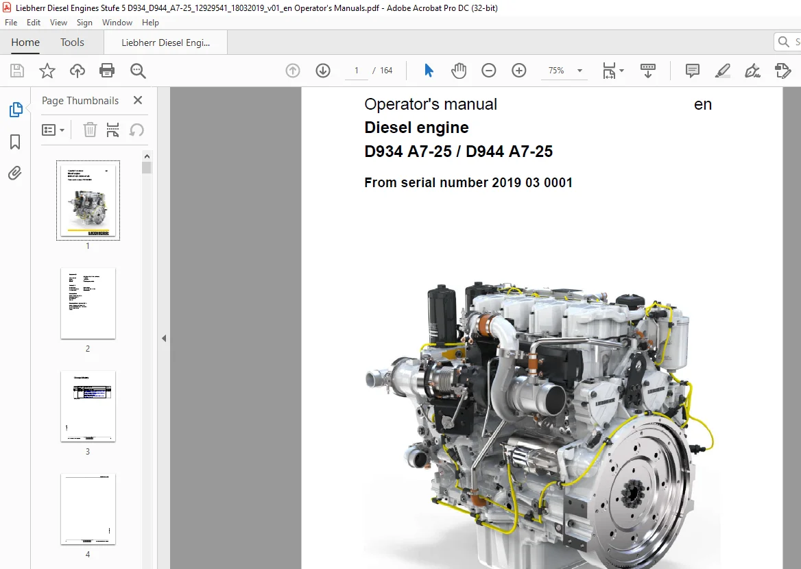
Liebherr Diesel engine D934 A7-25 D944 A7-25 Operating Manual – PDF DOWNLOAD
Original price was: $78.00.$25.95Current price is: $25.95.
Liebherr Diesel engine D934 A7-25 D944 A7-25 Operating Manual – PDF DOWNLOAD
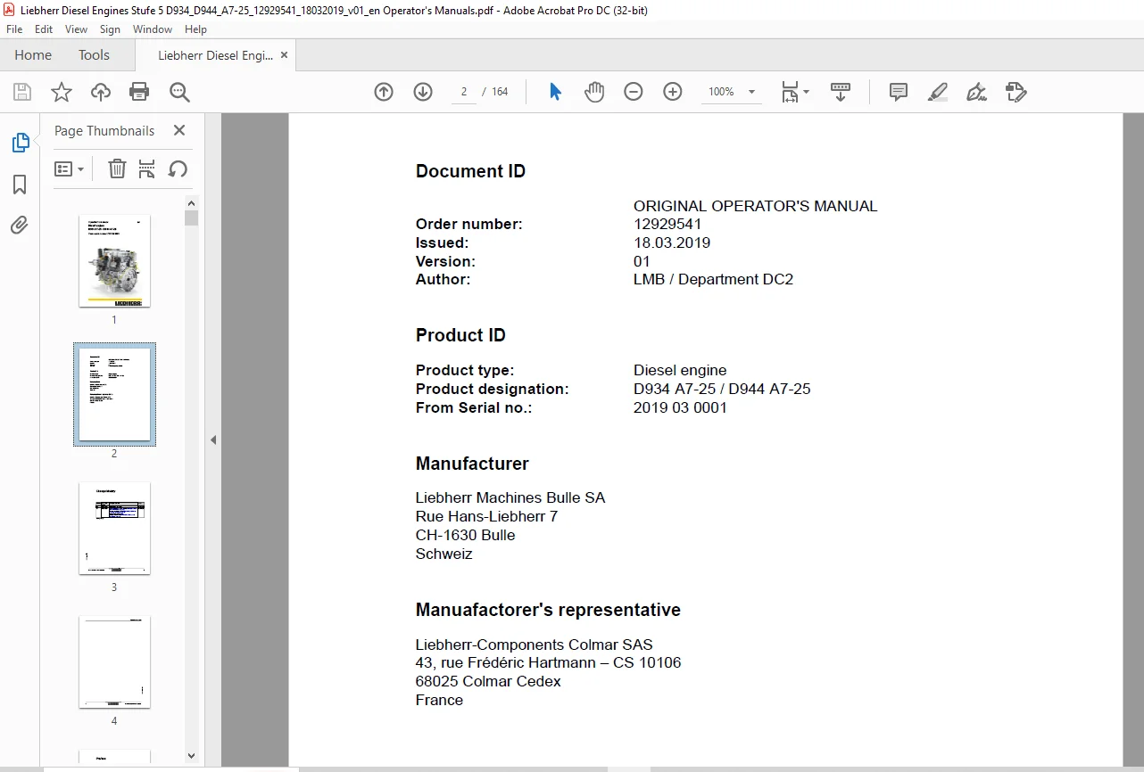
Product ID
Product type: Diesel engine
Product designation: D934 A7-25 / D944 A7-25
From Serial no.: 2019 03 0001
Description
Liebherr Diesel engine D934 A7-25 D944 A7-25 Operating Manual – PDF DOWNLOAD
FILE DETAILS:
Liebherr Diesel engine D934 A7-25 D944 A7-25 Operating Manual – PDF DOWNLOAD
Language : English
Pages :161
Downloadable : Yes
File Type : PDF
Size:5.71 MB
DESCRIPTION:
Liebherr Diesel engine D934 A7-25 D944 A7-25 Operating Manual – PDF DOWNLOAD
Product ID
Product type: Diesel engine
Product designation: D934 A7-25 / D944 A7-25
From Serial no.: 2019 03 0001
The descriptions for maintenance and care of the engine can be found in these operating instructions.
Work instructions
Spare parts
Lubricating and operating fluids
IMAGES PREVIEW OF THE MANUAL:
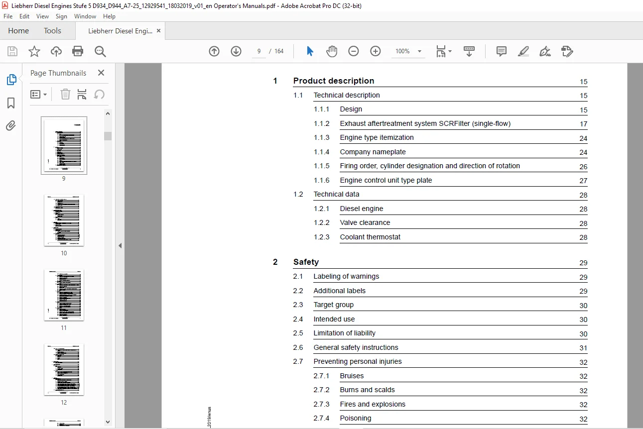
TABLE OF CONTENTS:
Liebherr Diesel engine D934 A7-25 D944 A7-25 Operating Manual – PDF DOWNLOAD
1 Product description 15
1.1 Technical description 15
1.1.1 Design 15
1.1.2 Exhaust aftertreatment system SCRFilter (single-flow) 17
1.1.3 Engine type itemization 24
1.1.4 Company nameplate 24
1.1.5 Firing order, cylinder designation and direction of rotation 26
1.1.6 Engine control unit type plate 27
1.2 Technical data 28
1.2.1 Diesel engine 28
1.2.2 Valve clearance 28
1.2.3 Coolant thermostat 28
2 Safety 29
2.1 Labeling of warnings 29
2.2 Additional labels 29
2.3 Target group 30
2.4 Intended use 30
2.5 Limitation of liability 30
2.6 General safety instructions 31
2.7 Preventing personal injuries 32
2.7.1 Bruises 32
2.7.2 Burns and scalds 32
2.7.3 Fires and explosions 32
2.7.4 Poisoning 32
2.7.5 High-pressure injection (liquids at high pressure can squirt out) 33
2.7.6 Electrical energy 33
2.7.7 Danger due to noise 33
2.8 Personal protective equipment 33
2.9 Operating areas and maintenance areas 34
2.9.1 Safety instructions 34
2.9.2 Operating areas 35
2.9.3 Maintenance areas 35
2.9.4 Secure and release the diesel engine against accidental starting 36
2.9.5 Emergency stop 37
2.10 Signage 37
2.11 Prevent material damages 38
3 Transport and storage 39
3.1 Dimensions and weights 39
3.2 Lifting the engine 40
3.3 Transport 42
3.3.1 Transport attachment 42
3.3.2 Transport device 43
3.4 Storage 45
3.4.1 Storage 45
3.4.2 Storage time 49
4 Operation 51
4.1 Preliminary work for the initial commissioning of the engine 51
4.2 Starting the engine 52
4.3 Turning off the engine 54
5 Maintenance 55
5.1 Maintenance schedule 55
5.2 Preliminary work 58
5.2.1 Bringing the engine into maintenance position 58
5.2.2 As needed 58
5.3 Diesel engine 61
5.3.1 Checking the V-ribbed belt 61
5.3.2 Checking the belt drive 62
5.3.3 Replacing the belt drive 63
5.3.4 Checking the engine mount 66
5.3.5 Checking the intake system for leaks and damage 67
5.3.6 Checking the exhaust system 68
5.4 Lubrication system 70
5.4.1 Checking the engine oil system for leaks and damage 70
5.4.2 Checking the engine oil level 73
5.4.3 Changing the engine oil 74
5.4.4 Replacing the oil separator filter insert 80
5.5 Cylinder head 83
5.5.1 Checking and setting the valve clearance 83
5.6 Cooling system 97
5.6.1 Checking the cooling system and heating system for leaks and damage 97
5.6.2 Checking the coolant level 98
5.6.3 Filling the coolant 98
5.6.4 Checking the concentration of the antifreeze agent in the coolant 99
5.6.5 Replacing the coolant 100
5.7 Fuel system 102
5.7.1 Checking the fuel system for leaks and damage 102
5.7.2 Checking the water separator on the fuel prefilter 103
5.7.3 Draining the water from the water separator in the fuel prefilter 103
5.7.4 Draining water and sediment from the fuel tank 103
5.7.5 Replacing the fuel prefilter 103
5.7.6 Reducing the pressure in the fuel system 104
5.7.7 Replacing the fuel fine filter 104
5.7.8 Ventilating the fuel system 107
5.8 Air filter 108
5.8.1 Checking the air filter low pressure indicator 108
5.8.2 Cleaning the air filter dust discharge valve 108
5.8.3 Replacing the dry air filter main element 108
5.8.4 Replacing the dry air filter safety element 108
5.9 Electrical system 109
5.9.1 Checking the batteries 109
5.9.2 Checking the cable connections 109
5.9.3 Checking the engine control unit bearings for damage 109
5.9.4 Checking sensors, actuators, cable holders and plugs 110
5.9.5 Checking the heating flange 112
5.9.6 Replacing the heating flange 116
5.10 Exhaust aftertreatment assembly 118
5.10.1 Checking the exhaust gas emission reduction assembly for leaks and
5.10.2 Checking components 120
5.10.3 Cleaning the SCR filter module 121
5.11 Lubricants and operating fluids 132
5.11.1 Fill quantities 132
5.11.2 Engine oil 132
5.11.3 Coolant 133
5.11.4 Fuel 133
6 Malfunctions 135
6.1 Faults – Cause – Remedy 135
7 Tools and devices 141
7.1 Tools 141
7.1.1 Special tool 141
7.1.2 Operating material 141
7.1.3 Diagnostic tools 142
7.2 Devices 143
7.2.1 Lifting traverse with three-point-raising (basic version) 143
7.2.2 Lifting traverse with two-point-raising 145
7.2.3 Engine assembly stand 146
7.2.4 Transport device 147
8 Appendix 149
8.1 Tightening torques 149
8.1.1 For hex bolts / cylinder screws / external hex bolts 149
8.1.2 For locking screws and banjo bolts 151
8.1.3 Standard torques for metric flange connections 152
8.1.4 Metric screw connection series L (light) (up to 500 bar/7252 Psi) 153
8.1.5 Metric screw connection series S (heavy) (up to 800 bar/11603 Psi) 154
8.1.6 Inch screw connection series L (light) (up to 500 bar/7252 Psi) 154
8.1.7 Inch screw connection series S (heavy) (up to 800 bar/11603 Psi) 155
8.1.8 Metric thread unit series L (light) (up to 500 bar/7252 Psi) for aluminum 156
8.2 Supplemental Information USA 160
8.2.1 Emission warranty 160
8.2.2 Warranted parts 160
8.2.3 RESPONSIBILITIES & LIMITATIONS 160
8.2.4 Exclusions 161
Customer Support: [email protected]
PLEASE NOTE:
- This is the SAME exact manual used by your dealers to fix your vehicle.
- The same can be yours in the next 2-3 mins as you will be directed to the download page immediately after paying for the manual.
- Any queries / doubts regarding your purchase, please feel free to contact [email protected]
S.M