Liebherr L 509 1581 Wheel Loader Service Manual – PDF DOWNLOAD
Original price was: $89.95.$31.95Current price is: $31.95.
Liebherr L 509 1581 Wheel Loader Service Manual – PDF DOWNLOAD
Description
Liebherr L 509 1581 Wheel Loader Service Manual – PDF DOWNLOAD
FILE DETAILS:
Liebherr L 509 1581 Wheel Loader Service Manual – PDF DOWNLOAD
Language : English
Pages : 692
Downloadable : Yes
File Type : PDF
Size: 137 MB
DESCRIPTION:
Liebherr L 509 1581 Wheel Loader Service Manual – PDF DOWNLOAD
- This service manual is designed for trained specialist staff of the Liebherr organisation and their dealers.
- This service manual contains specialist knowledge for repairing Liebherr construc- tion machines. Basic specialist knowledge on electronics, hydraulics, mechanics and engine technology is not contained in this service manual. Therefore special- ized training and qualifications are necessary. Liebherr recommends participating in the Liebherr training program for construction machines.
In this service manual you will find information on:
- You will find information on controls and operation in the operator’s manual. Information on spare parts are in the spare parts catalogue. Please observe the local accident prevention laws.
- You can find information on repairs of machine parts in the service documentation under “Wheel loader – repair instructions”.
Introduction:
To ensure safe operation:
- Consult with the worksite manager about safety regulations at the place of use.
- Adhere to safety regulations at the place of use.
- Follow traffic regulations.
- Adhere to valid guidelines provided by insurers (for example, employers’ professional liability insurance companies, accident insurance, etc.).
- Avoid working methods that can endanger safety.
- Adhere all intervals specified for recurrent checks and inspections as outlined in this operator’s manual.
1.2. Intended Use of Wheel Loader
The wheel loader is used to pick up, move, and dump the following materials:
- Soil
- Stones
- Broken rocks
- Bulk materials
This applies to a standard machine under normal operating conditions. Special applications are described in a separate options operator’s manual.
To ensure the intended use:
- Adhere to the operator’s manual.
- Follow maintenance intervals.
- Carry out inspection and maintenance tasks.
- Follow the specifications in the technical data.
- When using the machine on public roads, ensure it complies with applicable national regulations.
- Only lift loads with intended working attachments (fork prongs, crane boom), which must be properly fitted and functioning.
- Ensure that machines used underground (for mining and tunnel construction) are fitted with systems to reduce exhaust emissions (such as diesel particulate filters).
- Adhere to the requirements of each individual country for underground operation.
- For special uses, use special working attachments and, if necessary, special safety equipment.
- Exclusively mount and use special working attachments with approval and as per the stipulations of the manufacturer of the basic machine.
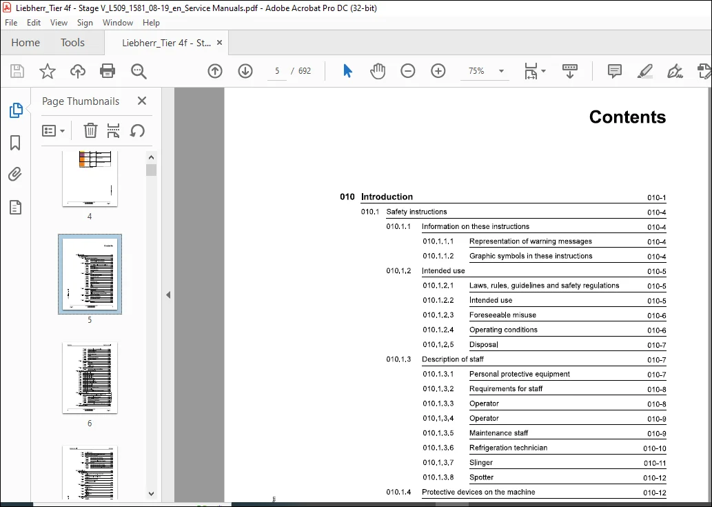
TABLE OF CONTENTS:
Liebherr L 509 1581 Wheel Loader Service Manual – PDF DOWNLOAD
010.1 Safety instructions 010-4
010.1.1 Information on these instructions 010-4
010.1.1.1 Representation of warning messages 010-4
010.1.1.2 Graphic symbols in these instructions 010-4
010.1.2 Intended use 010-5
010.1.2.1 Laws, rules, guidelines and safety regulations 010-5
010.1.2.2 Intended use 010-5
010.1.2.3 Foreseeable misuse 010-6
010.1.2.4 Operating conditions 010-6
010.1.2.5 Disposal 010-7
010.1.3 Description of staff 010-7
010.1.3.1 Personal protective equipment 010-7
010.1.3.2 Requirements for staff 010-8
010.1.3.3 Operator 010-8
010.1.3.4 Operator 010-9
010.1.3.5 Maintenance staff 010-9
010.1.3.6 Refrigeration technician 010-10
010.1.3.7 Slinger 010-11
010.1.3.8 Spotter 010-12
0101.4 Protective devices on the machine 010-12
010.1.4.1 Operator’s cab 010-12
010.1.4.2 Roll over protective structure (ROPS) 010-13
010.1.4.3 Falling object protective structures (FOPS) 010-13
0101.5 Emergency equipment on the machine 010-13
010.1.5.1 Emergency exit (standard) 010-13
010.1.5.2 Fire extinguisher (option) 010-14
010.1.6 Safe operation 010-14
010.1.6.1 Intoxicants 010-14
copyright ® Liebherr-Werk Bischofshofen GmbH 2019
L509-1681 LIEBHERR 5
Contents
010.3.1 Prestressing forces and tightening torques for bolts with metric
LBH/M2234435/06/211-20190801_070341/en
0104.2 Machine out of service for an unknown period of time 010-41
0104.3 Putting the machine out of service 010-42
010.4.3.1 Out of service for up to 2 months 010-42
010.4.3.2 Out of service for up to 12 months 010-43
010.4.3.3 Out of service for longer than 12 months 010-44
010.44 Putting back into service 010-44
010.441 After being out of service for 2 months 010-44
010.4.4.2 After being out of service for 12 months 010-45
020.1 Overall machine 020-4
020.1.1 Complete machine with bucket (z-bar kinematics)
L 509-1581; 020-4
020.1.2 Working attachment: light material bucket
L509-1581; 020-5
020.1.3 Working attachment: 4 in 1 bucket
L509-1581; 020-6
020.1.4 Working attachment: forklift
L509-1581; 020-8
020.2 Drive group 020-10
0202.1 Diesel engine
L509-1581/0-53994; 020-10
020.2.2 Diesel engine
L509-1581/53995-; 020-11
020.2.3 Fuel tank
L509-1581; 020-12
020.2.4 Fuel level sensor
L509-1581; 020-13
020.3 Cooling system 020-14
020.3.1 Fan pump
L509-1581; 020-14
020.3.2 Fan motor
L509-1581; 020-14
020.3.3 Hydraulic oil temperature sensor B8
L509-1581; 020-14
020.4 Working hydraulics 020-15
020.4.1 Working pump
L509-1581; 020-15
020.4.3 Pilot control unit
020.4.4 Pilot control hydro accumulator
020.4.5 Stabilisation module
020.4.6 Ride control hydro accumulator
020.4.7 Lift cylinder
020.4.8 Tilt cylinder
020.4.9 Working pump
Travel hydraulics 020-18
020.5.1 Travel pump
020.5.2 Travel pump high pressure sensor B45
020.5.3 Travel motor
Hydraulic components 020-20
020.6.1 Return suction filter
020.6.2 Breather filter with filler strainer
Steering system 020-21
020.7.1 Servostat
020.7.2 Steering cylinder
Brake system 020-22
020.8.1 Drum brake
020.8.2 Inch/brake unit
020.8.3 Brake light pressure switch B12
020.8.4 Spring accumulator cylinder for parking brake
Electrical system 020-24
LBH/M2234435/06/211-20190801_070341/en
0209.2 Compact module
L509-1581; 020-24
0209.3 Battery
L509-1581; 020-24
0209.4 Voltage transformer
L509-1581; 020-25
020.10 Gearbox 020-26
020.10.1 Transmission
L509-1581; 020-26
020.11 Axles and drive shafts 020-27
020.11.1 Front axle
L509-1581; 020-27
020.11.2 Rear axle
L509-1581; 020-27
020.11.3 Drive shaft
L509-1581; 020-27
020.11.4 Tyres
L509-1581; 020-27
020.11.4.2 Special tyres 020-28
020.12 Working attachment 020-30
020.12.1 Quick coupler locking hydraulic cylinder
L509-1581; 020-30
020.13 Operator’s cab, heating and air conditioning 020-31
020.13.1 Dryer
1509-1581; 020-31
020.13.2 Pressure switches
L509-1581; 020-31
020.14 Lubrication system 020-32
020.14.1 Central lubrication pump EP1
L509-1581; 020-32
020.14.2 Progressive distributor
L509-1581; 020-32
020.1421 MX-F 020-32
020.14.22 MX-F25 020-32
020.14.2.3 MX-F 45 020-32
020.14.24 MX-F75 020-33
020.14.25 MX-F105 020-33
Contents
030.1 Maintenance and inspection schedule 030-9
030.2 Filling quantities and lubrication chart 030-14
030.2.2 Recommended operating fluids
030.3.2 General information on changing lubricants and fuels 030-16
030.3.3 Converting hydraulic system from mineral oils to biodegradable
030.3.4 Diesel fuels
030.3.5 Engine oils
030.3.6 Refrigerant
030.3.7 Coolant
030.3.8 Hydraulic oil
LBH/M2234435/06/211-20190801_070341/en
030.3.9 Transmission
L509-1581; 030-21
030.3.9.1 Liebherr recommendation 030-21
030.3.9.2 Minimum quality requirement 030-21
030.3.10 Axle oil
L509-1581; 030-21
030.3.10.1 Liebherr recommendation 030-21
030.3.10.2 Minimum quality requirement 030-22
030.3.11 Brake oil
L509-1581; 030-22
030.3.11.1 Liebherr recommendation 030-22
030.3.12 Lubrication grease
L509-1581; 030-22
030.3.12.1 Liebherr recommendation 030-22
030.3.12.2 Minimum quality requirement 030-22
030.4 Maintenance tasks 030-24
0304.1 Safety precautions
L509-1581; 030-24
0304.2 Preparatory tasks for maintenance 030-24
030.421 Maintenance positions
L 509-1581; 030-25
030.4.2.2 Opening service hatches
L 509-1581; 030-26
030.4.2.3 Turning off battery main switch
L 509-1581; 030-27
030.4.3 Overall machine 030-28
030.4.3.1 Checking machine is in proper condition
L509-1581; 030-28
030.4.3.2 Removing loose parts, dirt, ice and snow from
machine
L 509-1581; 030-30
030.4.3.3 Cleaning machine
L509-1581; 030-30
030.4.3.4 Replacing VCI capsules
L 509-1581; 030-33
030.4.3.5 Qil analyses
L 509-1581; 030-36
030.44 Drive group 030-43
030.4.4.1 Checking diesel engine oil level
L509-1581; 030-43
030.4.4.2 Diesel engine: changing diesel engine oil
L 509-1581; 030-44
copyright ® Liebherr-Werk Bischofshofen GmbH 2019
L509-1581 LIEBHERR 1″
Contents Service manual
0304.43 Diesel engine: changing oil filter
L509-1581; 030-46
0304.4.4 Diesel engine: checking V-belt
1509-1581; 030-48
0304.4.5 Diesel engine: changing V-belt
L509-1581; 030-50
030.4.4.6 Checking diesel engine valve clearance
L509-1581; 030-51
030.447 Draining condensate and sediment from the fuel tank
L509-1581; 030-55
030.4.4.8 Draining off condensate from fuel pre-filter
L509-1581; 030-56
030.4.4.9 Changing fuel pre-filter element
L509-1581; 030-57
030.4.4.10 Changing fuel fine filter element
1509-1581; 030-58
030.4.4.11 Cleaning service cover and dust discharge valve of
air filter system
1509-1581; 030-60
030.4.4.12 Checking air filter vacuum switch function
L509-1581; 030-61
030.4.4.13 Cleaning or changing main element of air filter
system
1509-1581; 030-62
030.4.4.14 Changing safety element of air filter system
L509-1581; 030-65
030.4.4.15 Checking that diesel engine intake and exhaust
system is in good condition and not loose or leaking
L509-1581; 030-66
030.4.4.16 Cleaning or changing diesel particulate filter
L509-1581; 030-69
030.4.5 Cooling system 030-75
030.4.5.1 Checking coolant level in cooling system
1509-1581; 030-75
030.4.5.2 Checking coolant antifreeze and corrosion inhibitor
concentration
1509-1581; 030-77
0304.53 Cleaning cooling system
1509-1581; 030-84
0304.5.4 Changing coolant in cooling system
L509-1581; 030-85
030.46 Working hydraulics 030-88
030.4.6.1 Cleaning and lubricating the pilot control unit
1509-1581; 030-88
030.4.7 Hydraulic components 030-88
copyright ® Liebher-Werk Bischofshofen GmbH 2019
12 LIEBHERR 1509-1581
LBH/M2234435/06/211-20190801_070341/en
L509-1581; 030-88
030.4.7.2 Draining off condensate and sediment from hydraulic
tank
L 509-1581; 030-90
030.4.7.3 Changing the hydraulic tank return suction filter
cartridge
1509-1581; 030-91
030.4.7.4 Changing the hydraulic tank breather filter
L509-1581; 030-93
030.4.7.5 Hydraulic tank: analysing oil
L 509-1581; 030-93
030.4.7.6 Hydraulic tank: changing oil
L509-1581; 030-95
0304.8 Steering system 030-97
030.4.8.1 Steering: Checking the function
1509-1581; 030-97
030.4.8.2 Lubricating steering cylinder bearing
L 509-1581; 030-97
0304.9 Brake system 030-98
030.4.9.1 Testing service brake and parking brake
L509-1581; 030-98
030.4.9.2 Checking the oil level in the brake system
L509-1581; 030-100
030.4.9.3 Checking the gap and wear on the service brake
linings
L509-1581; 030-101
030.4.10 Electrical system 030-105
030.4.10.1 Checking function of lighting and horn
L509-1581; 030-105
030.4.10.2 Checking battery fluid levels and terminals
L509-1581; 030-106
030.4.10.3 Control lever: Change the travel direction switch
rocker and cap.
L509-1581; 030-108
030.4.11 Gearbox 030-111
030.4.11.1 Transmission: checking oil level
L509-1581; 030-111
030.4.11.2 Changing transmission oil
L509-1581; 030-111
030.4.12 Axles and drive shafts 030-113
030.4.12.1 Checking axle oil levels
L509-1581; 030-113
copyright © Liebherr-Werk Bischofshofen GmbH 2018
L509-1581 LIEBHERR 13
Contents Service manual
030.4.12.2 Changing axle oil
L509-1581; 030-115
0304.12.3 Lubricating rear axle kingpin bearings
1509-1581; 030-117
0304.12.4 Checking fitting of rear axle kingpin bearings and
steering rod taper connections
L509-1581; 030-118
0304.12.5 Checking tightening torque of front axle fastening
bolts
L509-1581; 030-119
0304.126 Checking and lubricating drive shaft
1509-1581; 030-120
030.4.12.7 Checking the tyre pressure
L509-1581; 030-121
030.4.12.8 Checking wheel tightness
1509-1581; 030-121
030.4.13 Steel parts of the basic machine 030-122
030.4.13.1 Lubricating articulated bearing
L509-1581; 030-122
0304.13.2 Lubricating articulation stops
L509-1581; 030-123
030.4.13.3 Lubricating the moving parts of the engine bonnet
with penetrating oil
1509-1581; 030-123
030.4.13.4 Cleaning and maintaining seals of service hatches
L509-1581; 030-124
030.4.14 Working attachment 030-124
030.4.14.1 Lubricating lift arms and working attachment
1509-1581; 030-124
030.4.14.2 Checking lift arm bucket bearing bushings
1509-1581; 030-125
030.4.14.3 Checking the lift arm bucket stops
L509-1581; 030-126
030.4.14.4 Testing quick coupler
L509-1581; 030-127
030.4.15 Operator’s cab, heating and air conditioning 030-128
030.4.15.1 Cleaning operator’s cab air filter
1509-1581; 030-128
0304.15.2 Changing operator’s cab air filter
L509-1581; 030-128
030.4.15.3 Safety belt: checking condition and function
1509-1581; 030-129
030.4.16.4 Testing the windscreen washer system
1509-1581; 030-130
copyright ® Liebher-Werk Bischofshofen GmbH 2019
14 LIEBHERR 1500-1581
LBH/M2234435/06/211-20190801_070341/en
1509-1581;
030.4.15.7 Cleaning and maintaining seals of operator’s cab
030.4.15.8 Air conditioning: checking V-belt
030.4.15.9 Air conditioning: changing V-belt
030.4.15.10 Checking the indicator bead in the air conditioning
030.4.15.11 Heating and air conditioning unit: Testing function
hoses and lubrication points for leaks and damage
1509-1581;
030.5 Testing and adjustment checklist
L509-1581; 030-141
030.6 Testing and adjustment tasks 030-145
0306.1 Safety precautions
L509-1581; 030-145
030.6.2 Overall machine 030-145
030.6.2.1 Preparing for adjustment procedures
1509-1581; 030-145
030.6.2.2 Hydraulic oil and coolant: operating temperature
1509-1581; 030-147
030.6.3 Drive group 030-148
030.6.3.1 Pedals: calibration
1509-1581; 030-148
030.6.3.2 Diesel engine speed
L509-1581; 030-149
030.6.3.3 Reading the diesel engine service files
1509-1581; 030-150
030.6.3.5 Diesel engine: changing engine control unit (ECU)
Cooling system 030-163
030.6.4.1 Fan motor: fan speed proportional solenoid
Working hydraulics 030-166
030.6.5.1 Control valve block: secondary pressure relief valves
030.6.5.2 Control valve block: primary pressure relief valve
0306.5.3 Control block: reduction of tilt-out speed (option)
030.6.5.4 Stabilisation module (option), safety valve
030.6.5.5 Ride control hydro accumulator (option): nitrogen
Hydraulic components 030-175
030.6.6.1 Checking the hydraulic lines for damage
Travel hydraulics 030-180
030.6.7.1 Travel pump high pressure sensor B102: Deviation
030.6.7.2 Travel pump replenishing pressure relief valve
030.6.7.3 Travel pump: high pressure relief valves
030.6.7.4 Travel pump: pressure cut-off
030.6.7.5 Travel pump: manual block curve calibration (up to
030.6.7.6 Travel pump: manual block curve calibration (from
030.6.7.7 Travel pump: automatic block curve calibration (from
0306.7.8 Travel motor: manual calibration (maximum swivel
L509-1581; 030-194
030.6.8.2 Angle sensor for inching function: checking basic
setting
1509-1581; 030-196
0306.9 Electrical system 030-197
030.6.9.1 Central control unit (Master4) Creating a Servicefile
L509-1581; 030-197
030.6.9.2 Updating the central controller software
1509-1581; 030-200
030.6.9.3 Setting the IP addresses of the central control unit
(Master4)
L509-1581; 030-202
030.6.9.4 Resetting the central control unit (Master4)
1509-1581; 030-205
030.6.9.5 Addressing CAN module and checking system infor-
mation
1509-1581; 030-206
030.6.10 Axles and drive shafts 030-208
030.6.10.1 Tyres: setting radius
L509-1581; 030-208
040 Drive group 040-1
040.1 Engine 040-2
040.1.1 Diesel engine overview
L509-1581; 040-2
040.1.2 Electrical components of diesel engine
L509-1581; 040-10
040.1.3 Fuel system 040-11
040.1.3.1 Overview of fuel system
L509-1581; 040-12
040.1.3.2 Fuel level sensor
L509-1581; 040-14
040.1.3.3 Fuel pre-filter
1509-1581; 040-15
040.1.3.4 Fuel fine filter
L509-1581; 040-16
040.14 Air filter system 040-17
040.1.4.1 Air filter
1509-1581; 040-17
040.1.4.2 Vacuum switch for air filter
1509-1581; 040-18
0401.5 Exhaust system 040-18
copyright ® Liebherr-Werk Bischofshofen GmbH 2019
1509-1581 LIEBHERR 17
Contents Service manual
050 Cooling system 050-1
050.1 Overview of cooling system
L509-1581; 050-2
050.2 Cooling system hydraulics 050-3
050.2.1 Overview of cooling system hydraulics
L509-1581; 050-3
050.22 Fan pump
1509-1581; 050-6
050.2.3 Fan motor
L509-1581; 050-7
050.3 Cooling system electronics 050-9
050.3.1 General overview of electronic control system
1509-1581; 050-9
050.3.2 Hydraulic oil temperature sensor
L509-1581; 050-12
050.4 Cooler 050-14
050.4.1 Cooler unit
1509-1581; 050-14
050.5 Reversible fan drive 050-15
050.5.1 Overview of reversible fan drive
L509-1581; 050-15
050.5.2 Fan reversal valve block
L509-1581; 050-18
060 Working hydraulics 060-1
060.1 Overview of working hydraulics
L509-1581; 060-3
060.2 Working pump
L509-1581; 060-9
0680.3 Control block
L509-1581; 060-12
060.4 Pilot control 060-20
060.4.1 Overview of pilot control unit
L509-1581; 060-20
060.4.2 Pilot control unit
L509-1581; 060-24
060.4.3 Pilot pressure for solenoid valve
1509-1581; 060-26
060.5 Ride control 060-28
LBH/M2234435/06/211-20190801_070341/en
060.5.2 Stabilisation module
L509-1581; 060-32
060.6 Regulated flow rate 060-37
0606.1 Regulated flow rate: total overview
L509-1581; 060-37
0606.2 Valve block for regulated flow rate
L509-1581; 060-39
060.7 Pipe break protection 060-41
060.7.1 Pipe break protection: overview
L509-1581; 060-41
060.7.2 Valve block for pipe break protection
L509-1581; 060-43
060.7.3 Solenoid valve for release of the ride control
L509-1581; 060-44
060.8 High flow 060-46
060.8.1 High Flow: total overview
L509-1581; 060-46
060.8.2 High Flow pump
L509-1581; 060-49
060.8.3 Solenoid valve for High Flow
L509-1581; 060-50
070 Travel hydraulics 070-1
070.1 Overview of travel hydraulics
L509-1581; 070-2
070.2 Travel pump
1509-1581; 070-8
070.3 Travel motors 070-24
070.3.1 Travel motor
L509-1581; 070-24
080 Hydraulic components 080-1
080.1 Hydraulic system: overview
1509-1581; 080-2
080.2 Hydraulic tank 080-4
080.2.1 Overview of the hydraulic tank
L509-1581; 080-4
0802.2 Return suction filter
L509-1581; 080-6
080.2.3 Breather filter
L509-1581; 080-12
copyright ® Liebherr-Werk Bischofshofen GmbH 2019
L509-1581 LIEBHERR 19
Contents Service manual
090.1 Steering system overview
L509-1581; 090-2
090.2 Servostat
L509-1581; 090-6
100 Brake system 100-1
100.1 Overview of brake system
L509-1581; 100-2
100.2 Service brake and parking brake 100-6
100.2.1 Drum brake
L509-1581; 100-6
100.3 Service brake 100-11
100.3.1 Inch/brake unit
L509-1581; 100-11
100.3.2 Inching function angle sensor
1509-1581; 100-12
100.3.3 Brake light pressure switch
L509-1581; 100-14
100.4 Parking brake 100-16
100.4.1 Parking brake solenoid valve
1509-1581; 100-16
100.4.2 Spring accumulator cylinder for parking brake
L509-1581; 100-17
110 Electrical system 110-1
110.1 Overview of electrical system
L509-1581; 110-2
110.2 Lighting
L509-1581; 110-5
110.3 Circuit diagrams
L509-1581; 110-7
110.4 Electronic control unit 110-9
110.4.1 General overview of electronic control system
1509-1581; 110-9
110.4.2 Central control unit (Master4)
L509-1581; 110-10
1104.3 Modules 110-15
110.4.3.1 Compact module: overview
L509-1581; 110-15
110.4.3.2 Compact module
1509-1581; 110-16
LBH/M2234435/06/211-20190801_070341/en
110.5.1 Fuse boards
L509-1581; 110-22
110.5.2 Door contact switch
L509-1581; 110-24
110.6 Electrical components in the rear section 110-25
110.6.1 Battery installation
L509-1581; 110-25
120 Gearbox 120-1
120.1 Overview of transmission
1509-1581; 120-2
120.2 Transmission electronics 120-3
120.2.1 Output speed sensor
L509-1581; 120-3
130 Axles and drive shafts 130-1
130.1 Axles 130-2
130.1.1 Front axle
L509-1581; 130-2
130.1.2 Rear axle
L509-1581; 130-4
130.2 Cardan shafts 130-6
130.2.1 Drive shaft
L509-1581; 130-6
140 Steel parts of the basic machine 140-1
140.1 Vehicle frame 140-2
140.1.1 Articulation bearing
L509-1581; 140-2
140.1.2 Articulation lock
L509-1581; 140-3
150 Working attachment 150-1
150.1 Lift arms for Z kinematics 150-2
160.1.1 Lift arms for Z kinematics
L509-1581; 150-2
150.2 Quick coupler 150-4
160.2.1 Quick coupler
L509-1581; 150-4
160.2.2 Quick coupler hydraulics 150-5
copyright ® Liebherr-Werk Bischofshofen GmbH 2019
509-1581 LIEBHERR 21
Contents Service manual
150.2.2.2 Open solenoid valve for quick coupler
1509-1581; 150-8
160 Operator’s cab, heating and air conditioning 160-1
160.1 Overview of operator’s cab, heating and air conditioning unit
L509-1581; 160-2
160.2 Display and control elements 160-4
160.2.1 Display
1509-1581; 160-4
160.2.2 Control lever
L 509-1581; 160-4
160.2.3 Accelerator pedal
1509-1581; 160-6
160.3 Heating, ventilation, air conditioning 160-8
160.3.1 Overview of heating, ventilation and air conditioning system
L509-1581; 160-8
160.3.2 Heating and air conditioning unit 160-14
160.3.2.1 Heating and air conditioning unit
1509-1581; 160-14
160.3.2.2 Blower
L509-1581; 160-17
160.4 Air conditioning 160-18
160.4.1 Air conditioning (optional)
1509-1581; 160-18
160.4.2 Compressor magnetic coupling
1509-1581; 160-19
160.4.3 Air conditioning condenser
L509-1581; 160-21
160.4.4 Dryer-collector unit
L 509-1581; 160-21
160.4.5 Air conditioning pressure switch
1509-1581; 160-23
170 Lubrication system 170-1
170.1 Liebherr automatic central lubrication system 170-2
170.1.1 Automatic central lubrication system: overview
L509-1581; 170-2
170.1.2 Central lubrication pump EP-1
1509-1581; 170-6
170.1.3 Progressive distributor MX-F
L 509-1581; 170-9
LBH/M2234435/06/211-20190801_070341/en
190.1 LiDAT 190-2
190.1.1 Overview of LiDAT
L509-1581; 190-2
190.1.2 LiDAT on machine
509-1581; 190-4
200 Diagnosis 200-1
200.1 Malfunctions 200-2
200.1.1 Warning symbols 200-2
200.1.2 Warning symbols 200-2
200.1.3 Service code indicator in display 200-3
200.2 Troubleshooting 200-6
200.2.1 Replacing fuses 200-6
200.2.1.1 Fuses on the fuse board in the cab 200-6
200.2.1.2 Fuses in right of engine compartment 200-9
Questions? Email us: [email protected]
IMAGES PREVIEW OF THE MANUAL:
PLEASE NOTE:
- This is the SAME exact manual used by your dealers to fix your vehicle.
- The same can be yours in the next 2-3 mins as you will be directed to the download page immediately after paying for the manual.
- Any queries / doubts regarding your purchase, please feel free to contact [email protected]
S.V