Liebherr L 524 1585 Wheel Loader Service Manual – PDF DOWNLOAD
Original price was: $89.95.$31.95Current price is: $31.95.
Liebherr L 524 1585 Wheel Loader Service Manual – PDF DOWNLOAD
Description
Liebherr L 524 1585 Wheel Loader Service Manual – PDF DOWNLOAD
FILE DETAILS:
Liebherr L 524 1585 Wheel Loader Service Manual – PDF DOWNLOAD
Language : English
Pages : 634
Downloadable : Yes
File Type : PDF
Size: 140 MB
DESCRIPTION:
Liebherr L 524 1585 Wheel Loader Service Manual – PDF DOWNLOAD
- This service manual is designed for trained specialist staff of the Liebherr organisation and their dealers.
- This service manual contains specialist knowledge for repairing Liebherr construc- tion machines. Basic specialist knowledge on electronics, hydraulics, mechanics and engine technology is not contained in this service manual. Therefore special- ized training and qualifications are necessary. Liebherr recommends participating in the Liebherr training program for construction machines.
In this service manual you will find information on:
- You will find information on controls and operation in the operator’s manual. Information on spare parts are in the spare parts catalogue. Please observe the local accident prevention laws.
- You can find information on repairs of machine parts in the service documentation under “Wheel loader – repair instructions”.
Safety instructions
General safety instructions
1. Familiarise yourself with the operator’s manual before starting up the
machine.
Make sure that you are in possession of additional instructions for any special
equipment installed on your machine, and that you have read and understood
them.
2. Only expressly authorised personnel may operate, service or repair the
machine.
Observe the legal minimum ages.
3. Only trained or instructed personnel may operate the machine. Clearly assign
responsibility for operation, rigging, maintenance and repair work.
4. The operator of the machine must ensure that no persons are in the operating
area of the machine on the basis of a risk assessment conducted in respect of
the operating site.
5. Clearly establish the driver’s responsibilities (also with respect to traffic regulations)
and authorise him to refuse to carry out unsafe instructions from third
parties.
6. Personnel undergoing training and instruction, or who are not yet fully qualified,
may only be allowed to work on the machine under constant supervision
by an experienced person.
7. Now and again, check that your personnel are working safely and are aware of
possible dangers in observance of the operator’s manual.
8. Wear safe working clothes when working on the machine.
Do not wear rings, wristwatches, ties, scarves, unbuttoned jackets, loose
clothing or similar garments, as they can become caught in the machinery and
cause injury.
Certain tasks require: safety glasses, safety boots, hard hats, protective
gloves, reflective vests, ear protection etc.
9. Ask the site manager about any special safety regulations in force on the
construction site.
10. Do not hold onto the steering column, the control panel or the control levers
when getting on or off the machine.
You might inadvertently trigger movements which could lead to accidents.
11. Never jump down from the machine. Use the steps, ladders and platforms
provided for getting on and off.
12. Keep all handles, steps, rails, gangways, platforms and ladders free from oil,
grease, mud snow and ice. This reduces the risk of slipping, tripping up or
falling.
13. Familiarise yourself with the emergency exit through the right cab door and/or
the rear window.
14. Unless there are other instructions, perform maintenance and repair work as
follows:
Procedure:
• Park the machine on firm, level ground and lower the working attachment
to the ground.
• Move all control levers to neutral.
• Turn off the diesel engine and take out the ignition key.
15. Before all work on the hydraulic system, depressurise the hydraulic circuits
and the hydraulic tank as described in the operator’s manual.
16. Lock the working hydraulics to prevent accidental actuation before leaving the
operator’s seat.
TABLE OF CONTENTS:
Liebherr L 524 1585 Wheel Loader Service Manual – PDF DOWNLOAD
010.1.12 Safety instructions for maintenance work on machines with hydro
010.1.17 Roll-over protection structure (ROPS) and falling object protection
010.2.2 Special tools for the diesel engine 010-16
010.2.3 Special tools for Z kinematics lift cylinder 010-17
010.2.4 Special tools for Z kinematics tilt cylinder 010-17
010.2.5 Special tools for P kinematics lift cylinder 010-18
010.2.6 Special tools for P kinematics tilt cylinder 010-18
010.2.7 Special tools for steering cylinders 010-18
010.2.8 Special tools for the electrical system 010-18
010.29 Special tools for axles 010-19
010.2.10 Special tools for the air conditioning system 010-19
010.2.11 Special tools for cab glazing 010-20
010.2.12 Special tools for the central lubrication system 010-20
Standards and regulations 010-22
010.3.1 Prestressing forces and tightening torques for bolts with metric
standard and fine threads as per DIN ISO 261 010-22
010.3.2 Assembly instructions for the piston and piston nut of the hydraulic
cylinder (WN 4121) 010-27
010.3.2.1 Range of application and purpose 010-27
010.3.2.2 Requirements and description 010-27
010.3.2.3 Amendments 010-32
010.3.2.4 Other applicable documents 010-32
010.3.2.5 Maximum adapter operating pressure 010-36
Preservation guidelines 010-38
010.4.1 General information 010-38
010.4.2 Out of service for an unknown period of time 010-38
010.4.3 Putting the machine out of service 010-39
010.4.3.1 Out of service for up to 2 months 010-39
010.4.3.2 Out of service for up to 12 months 010-40
010.4.3.3 Out of service for longer than 12 months 010-41
010.4.4 Putting back into service 010-41
0104.41 After being out of service for 2 months 010-41
0104.4.2 After being out of service for 12 months 010-42
010.4.4.3 After being out of service for longer than 12 months 010-42
020.1.1 Engine
L524-1585/34089-; 020-4
020.1.2 Fuel tank
L524-1585/34089-; 020-5
020.1.3 Fuel level sensor
L524-1585/34089-; 020-5
020.1.4 Fuel pre-filter (separator filter)
L524-1585/34089-; 020-5
020.1.5 Air filter vacuum switch
L524-1585/34089-; 020-56
020.1.6 Clutch
L524-1585/34089-; 020-6
020.2 Cooling system 020-7
020.2.1 Water cooler
L524-1585/34089-; 020-7
020.2.2 Fan gear pump
L524-1585/34089-; 020-7
020.2.3 Fan gear motor
L524-1585/34089-; 020-7
020.3 Working hydraulics 020-8
020.3.1 Working hydraulics pump
L524-1585/34089-; 020-8
020.3.2 Z kinematics control valve block
L524-1585/34089-; 020-8
020.3.3 P kinematics control valve block
L524-1585/34089-; 020-8
020.3.4 Pilot control hydro accumulator
L524-1585/34089-; 020-9
020.3.5 Stabilisation module (optional)
L524-1585/34089-; 020-9
020.3.6 Ride control hydro accumulator (optional)
L524-1585/34089-; 020-9
0203.7 Z kinematics lift cylinder
5 L524-1585/34089-; 020-9
3
g 020.3.8 Z kinematics tilt cylinder
8 L524-1585/34089-; 020-10
g 020.3.9 P kinematics lift cylinder
Tt L524-1585/34089-; 020-10
: 020.3.10 P kinematics tilt cylinder
§ L524-1585/34089-; 020-11
3 020.4 Travel hydraulics 020-12
020.4.1 Travel pump
L524-1585/34089-; 020-12
.2 Travel motor 1
020.4.3 Travel motor 2
Hydraulic components 020-14
020.5.1 Filter unit
020.5.2 Breather filter
Steering system 020-15
020.6.1 Servostat
020.6.2 Steering cylinder
020.6.3 Emergency steering pump
020.6.4 Emergency steering pressure switch B3
020.6.5 Emergency steering check pressure switch B3a
Brake system 020-17
020.7.1 Service brake hydro accumulator
020.7.2 Brake light pressure switch B12
020.7.3 Accumulator charge pressure switch B19
020.7.4 Disc brake
020.7.5 Parking brake hydro accumulator
Electrical system 020-19
020.8.1 Central control unit (UEC3)
020.8.2 Battery
020.8.3 Voltage transformer
Gearbox 020-21
020.9.1 Transmission
020.9.2 Output speed sensor B1 and travel motor 2 speed sensor B2
020.10.1 Front axle
L524-1585/34089-; 020-22
020.10.2 Rear axle
L524-1585/34089-; 020-22
020.10.3 Cardan shaft
L524-1585/34089-; 020-22
020.11 Steel parts of the basic machine 020-24
020.11.1 Ballast weight
L524-1585/34089-; 020-24
020.12 Operator’s cab, heating and air conditioning 020-25
020.12.1 Dryer
L524-1585/34089-; 020-25
020.12.2 Pressure switches
L524-1585/34089-; 020-25
020.12.3 Anti-icing temperature sensor
L524-1585/34089-; 020-25
030 Maintenance 030-1
030.1 Maintenance and inspection schedule 030-8
030.2 Filling quantities and lubrication chart 030-13
030.2.1 Recommended lubricants
L524-1585/34089-; 030-13
0302.2 Recommended operating fluids
L524-1585/34089-40516; 030-14
030.2.3 Recommended operating fluids
L524-1585/40517-; 030-14
030.3 Lubricants and fuels 030-15
030.3.1 General information on changing lubricants and fuels 030-15
030.3.2 Converting the hydraulic system from mineral oils to environmen-
tally harmless hydraulic fluids 030-15
030.3.3 Diesel fuels
L524-1585/34089-; 030-16
030.3.3.1 Specification 030-16
030.3.3.2 High sulphur content in the diesel fuel 030-16
030.3.3.3 Diesel fuel at low temperatures (winter operation) 030-17
030.3.4 Lubricating oils for diesel engines
L524-1585/34089-; 030-17
030.3.4.1 Lubricating oil quality 030-17
030.3.4.2 Lubricating oil viscosity 030-17
030.3.4.3 Lubricating oil change intervals 030-18
030.3.6 Coolants for diesel engines
030.3.7 Hydraulic oil
030.3.8 Lubricating oils for transmissions
030.3.9 Lubricating oils for axles
030.3.10 Lubrication grease and other lubricants
Maintenance tasks 030-31
030.4.1 Safety precautions
030.4.2 Preparatory tasks for maintenance 030-31
0304.2.2 Opening the service accesses
1.524-1585/34089-~; 030-33
L524-1585/34089-; 030-35
0304.3 Overall machine 030-35
030.4.3.1 Checking the machine for external damage
L524-1585/34089-; 030-35
030.4.3.2 Removing loose parts, dirt, ice and snow from the
machine
L524-1585/34089-; 030-35
030.4.3.3 Cleaning the machine
L524-1585/34089-; 030-36
030.4.3.4 Checking the machine for leaks
L524-1585/34089-; 030-37
030.4.3.5 Making sure the bolted connections are tight
1524-1585/34089-; 030-38
030.4.3.6 Corrosion protection system for use with salt and arti-
ficial fertilisers (optional): Carrying out corrosion
protection
L524-1585/34089-; 030-38
030.4.3.7 Oil analyses
L524-1585/34089-; 030-38
030.44 Drive group 030-44
030.4.4.1 Checking the engine oil level
1524-1585/34089-; 030-44
030.4.4.2 Changing the engine oil
L524-1585/34089-; 030-45
030.4.4.3 Changing the engine oil filter
L524-1585/34089-; 030-46
030.4.4.4 Checking the V-ribbed belt on the engine
L524-1585/34089-; 030-47
030.4.4.5 Changing V-ribbed belt of diesel engine
L524-1585/34089-; 030-48
030.4.4.6 Checking the engine valve clearance
L524-1585/34089-; 030-50
030.4.4.7 Checking the bleeder filter of the crankcase
L524-1585/34089-; 030-52
030.4.4.8 Checking the engine heating flange
L524-1585/34089-; 030-53
030.449 Draining off condensate and sediment from the fuel
tank
L524-1585/34089-; 030-54
030.4.4.10 Draining off condensate from the Separ fuel pre-filter
L524-1585/34089-; 030-55
030.4.4.11 Draining off condensate from the fuel pre-filter
L524-1585/34089-; 030-5
L524-1585/34089-; 030-57
030.4.4.13 Changing the fuel pre-filter
1.524-1585/34089-; 030-59
030.4.4.14 Changing the fuel fine filter
L524-1585/34089-; 030-60
030.4.4.15 Bleeding the fuel system
1.524-1585/34089-; 030-61
030.4.4.16 Cleaning the air filter service cover and dust
discharge valve
1.524-1585/34089-; 030-62
030.4.4.17 Checking the air suction system for leaks and tight
fitting
L524-1585/34089-; 030-64
030.4.4.18 Cleaning or changing the main filter element
1.524-1585/34089-; 030-65
030.4.4.19 Changing the air filter safety element
1.524-1585/34089-; 030-68
030.4.420 Checking the exhaust system for leaks and tight
fitting
1.524-1585/34089-; 030-69
030.4.5 Cooling system 030-70
030.4.5.1 Checking the coolant level
1.524-1585/34089-; 030-70
030.4.5.2 Checking the coolant antifreeze and corrosion inhib-
itor concentration
1.524-1585/34089-; 030-71
030.4.5.3 Cleaning the cooling system
L524-1585/34089-; 030-75
030.4.5.4 Changing the coolant
1.524-1585/34089-40516; 030-76
0304.5.5 Changing the coolant
L524-1585/40517-; 030-78
030.46 Working hydraulics 030-80
030.4.6.1 Lubricating the solenoids, universal joints and
tappets on the pilot control unit
1.524-1585/34089-; 030-80
030.4.7 Hydraulic components 030-81
030.4.7.1 Checking the oil level in the hydraulic tank
L524-1585/34089-; 030-81
030.4.7.2 Checking and cleaning the magnetic rod on the
hydraulic tank
1.524-1585/34089-35974; 030-82
0304.7.3 Checking and cleaning the magnetic rod on the
hydraulic tank
1.524-1585/35975-; 030-83
copyright ® Somatel-Liebherr SPA 2016
12 LIEBHERR 1524-1585
LBH/M1827890/06/211-20161102_144014/en
hydraulic tank
L524-1585/34089-; 030-84
030.4.7.5 Hydraulic tank – changing the return-suction filter
1 524-1585/34089-35974; 030-85
030.4.7.6 Changing the hydraulic tank return suction filter
L524-1585/35975-; 030-86
030.4.7.7 Changing the hydraulic tank breather filter
L524-1585/34089-; 030-87
030.4.7.8 Changing the oil in the hydraulic system in accord-
ance with oil quality and oil analysis
L524-1585/34089-; 030-87
030.4.8 Steering system 030-89
030.4.8.1 Testing the steering
L524-1585/34089-; 030-89
030.4.8.2 Lubricating the bearing points on the steering cylin-
ders
L524-1585/34089-; 030-90
0304.9 Brake system 030-91
030.4.9.1 Testing the service brake and parking brake
L524-1585/34089-; 030-91
030.4.9.2 Checking the service brake discs for wear
1524-1585/34089-; 030-92
030.4.9.3 Checking the gap and wear on the parking brake
linings
L524-1585/34089-; 030-94
030.4.10 Electrical system 030-97
030.4.10.1 Checking the lights
1.524-1585/34089-; 030-97
030.4.10.2 Checking the batteries, fluid level and terminals
L524-1585/34089-; 030-98
030.4.10.3 Changing the travel direction rocker switch and cap
(optional) on the control lever
1524-1585/34089-; 030-101
030.4.11 Gearbox 030-103
030.4.11.1 Checking the transmission oil level
L524-1585/34089-; 030-103
030.4.11.2 Changing the transmission oil
L524-1585/34089-; 030-103
030.4.12 Axles and drive shafts 030-104
030.4.12.1 Checking the axle oil levels
L524-1585/34089-; 030-104
030.4.12.2 Changing the axle oil
L524-1585/34089-; 030-105
copyright ® Somatel-Liebherr SPA 2016
1524-1585 LIEBHERR 13
Contents
fastening bolts
1.524-1585/34089-; 030-107
030.4.12.4 Checking the cardan shafts
1.524-1585/34089-; 030-107
0304.12.5 Checking the tyre pressure
L524-1585/34098-; 030-108
0304.126 Checking the wheel tightness (once after 50, 100 and
250 h)
L524-1585/34089-; 030-108
030.4.13 Steel parts of the basic machine 030-109
030.4.13.1 Lubricating the articulation bearing and the rear axle
oscillating bearing
1.524-1585/34089-; 030-109
030.4.13.2 Covering – lubricating locks and hinges
L524-1585/34089-; 030-110
030.4.14 Working attachment 030-111
030.4.14.1 Lubricating the lift arms and attachment
L524-1585/34089-; 030-111
0304.14.2 Checking the lift arm bearing bushings
L524-1585/34089-; 030-112
0304.14.3 Checking the lift arm bucket stops (Z kinematics)
1.524-1585/34089-; 030-113
030.4.14.4 Lubricating and testing the quick-change device
1.524-1585/34089-; 030-114
030.4.15 Operator’s cab, heating and air conditioning 030-115
030.4.15.1 Cleaning the fresh and recirculated air filters
L524-1585/34089-; 030-115
030.4.15.2 Changing the fresh and recirculated air filters
1.524-1585/34089-; 030-117
030.4.15.3 Checking the condition and function of the safety belt
L524-1585/34089-; 030-118
0304.15.4 Checking and topping up the windscreen washer
reservoir
L524-1585/34089-; 030-118
030.4.15.5 Checking the seals on the driver’s cab
1.524-1585/34089-; 030-119
030.4.15.6 Checking the indicator and filling level beads in the
dryer-collector unit of the air conditioner
L524-1585/34089-; 030-119
030.4.15.7 Testing the air conditioning unit
1.524-1585/34089-; 030-120
030.4.16 Lubrication system 030-121
level
L524-1585/34089-; 030-121
the lubrication system
L524-1585/34089-; 030-122
030.6 Testing and adjustment tasks 030-127
0306.1 Safety precautions
L524-1585/34089-; 030-127
0306.2 Overall machine 030-128
030.6.2.1 Preparatory tasks for testing and adjustment
L524-1585/34089-; 030-128
030.6.2.2 Bringing the machine up to operating temperature
1 524-1585/34089-; 030-129
0306.3 Drive group 030-130
030.6.3.1 Inch/brake pedal calibration
L524-1585/34089-; 030-130
030.6.3.2 Checking the engine speed
L524-1585/34089-; 030-130
030.6.3.3 Engine: Reading the service files
L524-1585/34089-; 030-131
0306.4 Cooling system 030-134
030.6.4.1 Fan gear motor proportional pressure relief valve
L524-1585/34089-; 030-134
030.6.5 Working hydraulics 030-136
030.6.5.1 Working hydraulics pump flow regulator (standby
pressure)
L524-1585/34089-; 030-136
030.6.5.2 Z kinematics control valve block secondary pressure
relief valves
L524-1585/34089-; 030-138
030.6.5.3 Working hydraulics LS pressure cut-off
L524-1585/34089-; 030-139
030.6.5.4 P kinematics control valve block secondary pressure
relief valves
L524-1585/34089-; 030-141
030.6.5.5 Stabilisation module (optional), cut-off function
L524-1585/34089-; 030-142
030.6.5.7 Testing the control valve block for leakage
Travel hydraulics 030-149
030.6.6.1 Travel pump replenishing pressure relief valve
030.6.6.2 Travel pump high pressure relief valves
030.6.6.3 Travel pump pressure cut-off
030.6.6.4 Travel pump block curve calibration
030.6.6.5 Travel motor 1 start of regulation
030.6.6.6 Travel motor 2 automatic calibration
0306.6.7 Engine output
Steering system 030-160
030.6.7.1 Steering system LS pressure cut-off
Brake system 030-161
function
030.6.8.2 Service brake pressure
030.6.8.3 Service brake hydro accumulator capacity
030.6.9.2 Resetting central control unit (UEC3)
Gearbox 030-176
030.6.10.1 Transmission hydro accumulator nitrogen filling
040 Drive group 040-1
040.1 Engine 040-2
0401.1 Diesel engine overview
L524-1585/34089-; 040-2
040.1.2 Crankshaft speed sensor
L524-1585/34089-; 040-6
040.1.3 Fuel temperature sensor
L524-1585/34089-; 040-7
040.14 Charge air temperature sensor
L524-1585/34089-; 040-7
0401.5 Fuel system 040-8
040.1.5.1 Overview of the fuel system
L524-1585/34089-; 040-8
040.1.5.2 Fuel pre-filter
L524-1585/34089-; 040-15
040.1.5.3 Separ fuel pre-filter
L524-1585/34089-; 040-16
040.1.5.4 Fuel fine filter
L524-1585/34089-; 040-17
040.16 Air filter system 040-17
040.1.6.1 Overview of the air filter unit
L524-1585/34089-; 040-18
040.1.6.2 Air filter
L524-1585/34089-; 040-19
040.2 Coupling
L524-1585/34089-; 040-20
050 Cooling system 050-1
050.1 Overview of the cooling system
1L.524-1585/34089-; 050-2
050.2 Cooling system hydraulics 050-4
050.2.1 Overview of the hydraulics cooling system
L524-1585/34089-; 050-4
050.2.2 Fan gear pump
L524-1585/34089-; 050-6
050.2.3 Fan gear motor
L524-1585/34089-; 050-7
050.3 Cooling system electronics 050-11
050.3.1 Coolant temperature sensor
L524-1585/34089-; 050-11
050.3.2 Hydraulic oil temperature sensor
L524-1585/34089-; 050-12
050.4 Cooler 050-16
050.4.1 Water cooler
L524-1585/34089-; 050-16
050.4.2 Hydraulic oil cooler
1L524-1585/34089-; 050-17
050.4.3 Intercooler
1 524-1585/34089-; 050-19
050.5 Reversible fan drive 050-20
050.5.1 Reversible fan drive
1 524-1585/34089-; 050-20
Working hydraulics 060-1
060.1 Overview of z kinematics working hydraulics
L524-1585/34089-; 060-3
060.2 Overview of working hydraulics for p kinematics
L524-1585/34089-; 060-8
060.3 Working hydraulics pump
L524-1585/34089-; 060-13
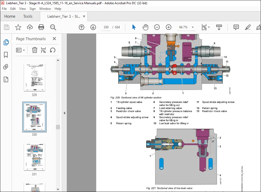
080.4 Control valve block for Z-bar kinematics
L524-1585/34089-; 060-17
060.5 Control valve block for P kinematics
L524-1585/34089-; 060-23
060.6 Pilot control 060-28
060.6.1 Overview of the pilot control unit
1L524-1585/34089-; 060-28
060.6.2 Pilot control unit
1 524-1585/34089-; 060-29
060.6.3 Working hydraulics lockout solenoid valve
L524-1585/34089-; 060-34
060.6.4 Pilot control hydro accumulator
1524-1585/34089-; 060-35
060.7 Ride control 060-36
060.7.1 Ride control overview
1 524-1585/34089-; 060-36
060.7.2 Stabilisation module
L524-1585/34089-; 060-37
060.7.3 Ride control hydro accumulator
1524-1585/34089-; 060-42
060.8 Working hydraulics cylinder 060-43
060.8.1 Hydraulic cylinders for Z kinematics 060-43
LBH/M1827890/06/211-20161102_144014/en
060.8.1.2 Z kinematics tilt cylinder
1 524-1585/34089-; 060-45
060.8.2 Hydraulic cylinders for P kinematics 060-46
060.8.2.1 P kinematics lift cylinder
L524-1585/34089-; 060-47
060.8.2.2 P kinematics tilt cylinder
1 524-1585/34089-; 060-48
070 Travel hydraulics 070-1
070.1 Travel hydraulics overview
L524-1585/34089-36291; 070-2
070.2 Travel hydraulics overview
1524-1585/36292-; 070-7
070.3 Travel pump
1524-1585/34089-36291; 070-12
070.4 Travel pump
L524-1585/36292-; 070-26
070.5 Travel motors 070-41
070.5.1 Overview of the travel motors
L524-1585/34089-; 070-41
0705.2 Travel motor 1
L524-1585/34089-; 070-43
070.5.3 Travel motor 2
L524-1585/34089-; 070-50
080 Hydraulic components 080-1
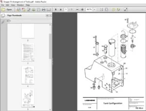
080.1 Hydraulic tank 080-2
080.1.1 Overview of the hydraulic tank
L524-1585/34089-; 080-2
080.1.2 Filter unit
L524-1585/34089-; 080-4
080.1.3 Breather filter
L524-1585/34089-; 080-9
090 Steering system 090-1
090.1 Steering system overview
L524-1585/34089-35802; 090-2
090.2 Steering system overview
1524-1585/35803-; 090-6
090.3 Servostat
L524-1585/34089-; 090-10
copyright ® Somatel-Liebherr SPA 2016
1524-1585 LIEBHERR 19
Contents
090.4.1 Steering cylinder overview
1 524-1585/34089-35802; 090-14
090.4.2 Steering cylinder overview
L524-1585/35803~; 090-16
090.4.3 Steering damper hydro accumulator
L524-1585/35803-; 090-18
090.5 Emergency steering 090-19
090.5.1 Emergency steering overview
L524-1585/34089-; 090-19
090.5.2 Emergency steering pump
1524-1585/34089-; 090-20
090.5.3 Emergency steering electronics 090-22
090.5.3.1 Overview of the electronic control system
1.524-1585/34089-; 090-22
090.5.3.2 Emergency steering pressure switch
1.524-1585/34089-; 090-23
090.5.3.3 Emergency steering check pressure switch
L524-1585/34089-~; 090-24
090.54 Valve block
1524-1585/34089-; 090-25
100 Brake system 100-1
100.1 Overview of the brake system
L524-1585/34089-; 100-2
100.2 Service brake and parking brake 100-4
100.2.1 Brake system gear pump
1524-1585/34089-; 100-4
100.2.2 Compact brake valve
L524-1585/34089; 100-5
100.3 Service brake 100-12
100.3.1 Overview of the service brake
1524-1585/34089-; 100-12
100.3.2 Service brake hydro accumulator
L524-1585/34089-; 100-15
100.3.3 Brake light pressure switch
1524-1585/34089-; 100-16
100.3.4 Accumulator charge pressure switch
L524-1585/34089-; 100-17
100.4 Parking brake 100-18
100.4.1 Overview of the parking brake
1524-1585/34089-; 100-18
LBH/M1827890/06/211-20161102_144014/en
100.4.3 Parking brake hydro accumulator
L524-1585/34089-; 100-22
110 Electrical system 110-1
110.1 Overview of the electrical system
1524-1585/34089-; 110-2
110.2 Lighting
L524-1585/34089-; 110-7
110.3 Circuit diagrams
1L.524-1585/34089-; 110-9
110.4 Electronic control unit 110-11
110.4.1 Overview of the electronic control system
L524-1585/34089-; 110-11
110.4.2 Central control unit (UEC3)
L524-1585/34089-; 110-13
110.5 Electrical components of the driver’s cab 110-18
110.5.1 Fuse and relay board
L524-1585/34089-; 110-18
110.6 Electrical components in the rear section 110-22
110.6.1 Battery installation
L524-1585/34089-; 110-22
120 Gearbox 120-1
120.1 Overview of the transmission
1L.524-1585/34089-; 120-2
120.2 Mechanical transmission
1.524-1585/34089-; 120-3
120.3 Transmission hydraulics 120-9
120.3.1 Overview of the hydraulic control system
L524-1585/34089-; 120-9
120.4 Transmission electronics 120-13
120.41 Overview of the electronic control system
L524-1585/34089-; 120-13
120.4.2 Output speed sensor and travel motor 2 speed sensor
L524-1585/34089-; 120-14
120.4.3 Coupling pressure switch
L524-1585/34089-; 120-15
130 Axles and drive shafts 130-1
130.1 Axles 130-2
130.1.2 Rear axle
1524-1585/34089-; 130-7
130.2 Cardan shafts 130-8
130.2.1 Cardan shaft
L524-1585/34089-; 130-8
140 Steel parts of the basic machine 140-1
140.1 Vehicle frame 140-2
140.1.1 Articulation bearing
1524-1585/34089-; 140-2
140.1.2 Articulation lock
L524-1585/34089-; 140-3
150 Working attachment 150-1
150.1 Lift arms with Z kinematics 150-2
150.1.1 Z kinematics lift arms
L524-1585/34089-; 150-2
1560.1.2 Pin bearing 150-2
150.1.2.1 Z kinematics standard pin bearing
L524-1585/34089~; 150-3
160.2 Lift arms with P kinematics 150-4
160.2.1 P kinematics lift arm
1524-1585/34089-; 150-4
160.3 Quick coupler 150-5
1560.3.1 Z kinematics quick coupler
L524-1585/34089-; 150-5
150.3.2 P kinematics quick coupler
L524-1585/34089-; 150-8
160 Operator’s cab, heating and air conditioning 160-1
160.1 Overview of the cab, heating and air conditioning unit
L524-1585/34089-; 160-3
160.2 Display and control elements 160-5
160.2.1 Electrical components in the control panel 160-5
160.2.1.1 Overview of electrical components in the control
panel
1.524-1585/34089-; 160-5
160.2.1.2 Control unit for main functions
L524-1585/34089-; 160-5
160.2.2 Display
L524-1585/34089-; 160-9
160.2.3 Control lever
L524-1585/34089-; 160-10
160.3 Heating, ventilation, air conditioning 160-13
160.3.1 Overview of the heating, ventilation and air conditioning system
L524-1585/34089-; 160-13
160.3.2 Heating and air conditioning unit 160-16
160.3.2.1 Heater/blower unit
1 524-1585/34089-; 160-16
160.3.2.2 Blower
L524-1585/34089-; 160-19
160.4 Air conditioning 160-20
160.4.1 Condenser
L524-1585/34089-; 160-20
160.4.2 Dryer
L524-1585/34089-; 160-21
160.4.3 Air conditioning pressure switch
L524-1585/34089-; 160-22
160.44 Evaporator
L524-1585/34089-; 160-23
200 Diagnosis 200-1
200.1 Malfunctions 200-2
200.1.1 Warning symbols 200-2
200.1.2 Service code indicator in the display 200-2
200.2 Troubleshooting 200-5
200.21 Replacing fuses 200-5
200.2.1.1 Fuses in the battery compartment 200-5
200.2.1.2 Plug-in fuses on the relay and fuse board 200-6
Customer Support: [email protected]
https://vimeo.com/830189820?share=copy
IMAGES PREVIEW OF THE MANUAL:
PLEASE NOTE:
- This is the same manual used by the DEALERSHIPS to SERVICE your vehicle.
- The manual can be all yours – Once payment is complete, you will be taken to the download page from where you can download the manual. All in 2-5 minutes time!!
- Need any other service / repair / parts manual, please feel free to contact us at heydownloadss @gmail.com . We may surprise you with a nice offer
S.V