Liebherr L 526 1753 Wheel Loader Technical Service Manual PDF
Original price was: $86.95.$34.95Current price is: $34.95.
Liebherr L 526 1753 Wheel Loader Service Manual – PDF DOWNLOAD
Description
Liebherr L 526 1753 Wheel Loader Service Manual – PDF DOWNLOAD
FILE DETAILS:
Liebherr L 526 1753 Wheel Loader Service Manual – PDF DOWNLOAD
Language : English
Pages : 962
Downloadable : Yes
File Type : PDF
Size: 147 MB
DESCRIPTION:
Liebherr L 526 1753 Wheel Loader Service Manual – PDF DOWNLOAD
- This service manual is designed for trained specialist staff of the Liebherr organisation and their dealers.
- This service manual contains specialist knowledge for repairing Liebherr construc- tion machines. Basic specialist knowledge on electronics, hydraulics, mechanics and engine technology is not contained in this service manual. Therefore special- ized training and qualifications are necessary. Liebherr recommends participating in the Liebherr training program for construction machines.
In this service manual you will find information on:
- You will find information on controls and operation in the operator’s manual. Information on spare parts are in the spare parts catalogue. Please observe the local accident prevention laws.
- You can find information on repairs of machine parts in the service documentation under “Wheel loader – repair instructions”.
Introduction:
To ensure safe operation:
– Ask work site manager for safety regulations at place of use.
– Adhere to safety regulations at place of use.
-Adhere to traffic regulations.
-Adhere to valid guidelines from insurers (for example employers’ professional liability insurance companies, accident insurance et cetera).
-Avoid working methods that can endanger safety.
-Adhere to all intervals specified for recurrent checks and inspections in this
operator’s manual.
Intended use:
Wheel loader is used to pick up, move and dump following materials:
– Soil
– Stones
– Broken rocks
– Bulk materials
This applies to a standard machine in normal operating conditions. Special applications are described in a separate options operator’s manual.
To ensure intended use:
– Adhere to operator’s manual.
– Adhere to maintenance intervals.
– Observe inspection and maintenance tasks.
– Adhere to specifications in the technical data.
– When using machine on public roads, make sure it complies with applicable national regulations.
– Only lift loads with intended working attachments (fork prongs, crane boom), which must be fitted and functioning.
– Make sure that machines used underground (mining and tunnel construction) are fitted with systems to reduce exhaust emissions (such as diesel particulate filters).
– Adhere to individual country’s requirements for underground operation.
– For special uses use special working attachments and if necessary special safety equipment.
– Exclusively mount and use special working attachments with approval and as per stipulations of manufacturer of basic machine.
– Only use approved tyres.
– A suitably equipped workshop is absolutely essential for performing repair work.
TABLE OF CONTENTS:
Liebherr L 526 1753 Wheel Loader Service Manual – PDF DOWNLOAD
010.1 Safety instructions 010-4
010.1.1 Information on these instructions 010-4
010.1.1.1 Representation of warning messages 010-4
010.1.1.2 Graphic symbols in these instructions 010-4
010.1.2 Intended use 010-5
010.1.2.1 Laws, rules, guidelines and safety regulations 010-5
010.1.2.2 Intended use 010-5
010.1.2.3 Foreseeable misuse 010-6
010.1.2.4 Operating conditions 010-6
010.1.2.5 Disposal 010-7
010.1.3 Description of staff 010-7
010.1.3.1 Personal protective equipment 010-7
010.1.3.2 Requirements for staff 010-8
010.1.3.3 Operating company 010-8
010.1.3.4 Operator 010-9
010.1.3.5 Maintenance staff 010-9
010.1.3.6 Refrigeration technician 010-10
010.1.3.7 Slinger 010-11
010.1.3.8 Spotter 010-12
0101.4 Protective devices on the machine 010-12
010.1.4.1 Operator’s cab 010-12
010.1.4.2 Roll over protective structure (ROPS) 010-13
010.1.4.3 Falling object protective structures (FOPS) 010-13
0101.5 Emergency equipment on the machine 010-13
010.1.5.1 Emergency exit (standard) 010-13
010.1.5.2 Fire extinguisher (option) 010-14
010.1.6 Safe operation 010-14
010.1.6.1 Intoxicants 010-14
010.1.6.3 Transporting machine 010-15
010.1.6.4 Access to machine 010-15
010.1.6.5 Machine danger zone 010-16
010.1.6.6 Visibility 010-16
010.1.6.7 Protection against vibration 010-17
010.1.6.8 Operation of machine 010-18
010.1.7 Safe maintenance 010-21
010.1.7.1 Spare parts 010-21
010.1.7.2 Heavy parts 010-21
010.1.7.3 Regular checks 010-22
010.1.8 Modifications to the machine 010-22
010.1.8.1 Modifications, add-ons and retrofittings 010-22
Special tools for maintenance and repair work 010-23
010.21 Special tools, general 010-23
010.2.2 Special tools for the engine 010-25
010.2.3 Special tools for lift cylinders with Z kinematics 010-29
010.2.4 Special tools for tilt cylinders with Z kinematics 010-30
010.2.5 Special tools for lift cylinders with P kinematics 010-30
010.2.6 Special tools for tilt cylinders with P kinematics 010-31
010.2.7 Special tools for steering wheel 010-32
010.2.8 Special tools for steering cylinders 010-32
010.2.8 Special tools for the electrical system 010-33
010.2.10 Special tools for front axle 010-34
010.2.11 Special tools for rear axle 010-34
010.2.12 Special tools for air conditioning system 010-35
010.2.13 Special tools for cab glazing 010-36
010.2.14 Special tools for the central lubrication system (Liebherr) 010-36
010.3.1.1 Range of application and purpose 010-38
010.3.1.2 Other applicable documents 010-38
010.3.1.3 Modifications and descriptions 010-39
010.4.1 General information 010-46
010.4.2 Machine out of service for an unknown period of time 010-46
0104.3 Putting the machine out of service 010-47
020.1.1 Complete machine with loading bucket (z-bar kinematics)
0201.2 Complete machine with loading bucket (parallel kinematics)
0201.3 Working attachment: light material bucket
020.14 Working attachment: high dump bucket
020.1.5 Working attachment: forklift
020.16 Working attachment: log grappler
L526-1753; 020-15
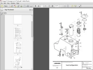
0202.2 Fuel tank
L526-1753; 020-16
020.2.2.1 Plastic version 020-16
020.2.2.2 Steel version (optional) 020-16
020.2.2.3 Diesel exhaust fluid tank 020-16
0202.3 Fuel level sensor
L526-1753; 020-16
020.24 Fuel pre-filter
L526-1753; 020-17
copyright ® Liebherr-Werk Bischofshofen GmbH 2021
L526-1753 LIEBHERR 7
Contents
020.3 Cooling system 020-18
020.3.1 Fan pump
L526-1753; 020-18
020.3.2 Fan motor
L526-1753/0-60945; 020-18
020.3.3 Fan motor
1 526-1753/60946-; 020-18
020.3.4 Hydraulic oil temperature sensor B8
1526-1753; 020-18
020.4 Working hydraulics 020-19
020.4.1 Control block for Z-bar kinematics
L526-1753; 020-19
020.4.2 Control block for P-kinematics
1526-1753; 020-19
020.4.3 Pilot control unit
L526-1753; 020-20
020.4.4 Pilot control hydro accumulator
L526-1753; 020-20
020.4.5 Stabilisation module
1526-1753; 020-20
020.46 Ride control hydro accumulator
1526-1753; 020-20
020.4.7 Z kinematics lift cylinder
L526-1753; 020-20
020.4.8 Z kinematics tilt cylinder
1526-1753; 020-21
020.4.9 P-kinematics lift cylinder
1526-1753; 020-21
020.4.10 P-kinematics tilt cylinder
1526-1753; 020-22
020.5 Travel hydraulics 020-23
020.5.1 Travel pump high pressure sensor B45
L526-1753; 020-23
020.6 Hydraulic components 020-24
020.6.1 Return suction filter
L526-1753; 020-24
020.6.2 Breather filter
L526-1753; 020-24
020.7 Steering system 020-25
020.7.1 Servostat
L526-1753; 020-25
copyright © Liebher-Werk Bischofshofen GmbH 2021
8 LIEBHERR 1526-1753
Service manual
L526-1753; 020-25
020.7.3 Steering damper hydro accumulator
L526-1753; 020-25
020.74 Emergency steering pump
L526-1753; 020-25
020.7.5 Emergency steering pressure switch B3
L526-1753; 020-26
020.7.6 Emergency steering check pressure switch B3a
L526-1753; 020-26
020.7.7 Joystick steering control valve block
L526-1753; 020-26
020.8 Brake system 020-28
020.8.1 Brake pump
L526-1753; 020-28
0208.2 Compact brake valve
L526-1753; 020-28
020.8.3 Service brake hydro accumulator
L526-1753; 020-28
020.8.4 Brake light pressure switch B12
1526-1753; 020-28
020.8.5 Brake accumulator pressure sensor B19
L526-1753; 020-28
0208.6 Parking brake hydro accumulator
L526-1753; 020-29
020.9 Electrical system 020-30
0209.1 Central control unit (Master5-Premium)
L526-1753; 020-30
0209.2 Compact module
L526-1753; 020-30
020.10 Gearbox 020-31
020.10.1 Transmission
L526-1753; 020-31
2 020.10.2 Gear shifting proportional solenoid valve Y60
g L526-1753; 020-31
oF
5 020.10.3 Output B1 speed sensor
8 L526-1753; 020-31
§ 020.10.4 Travel motor 2 speed sensor B2
g L526-1753; 020-31
g 020.11 Axles and drive shafts 020-32
3 020.11.1 Front axle
L526-1753; 020-32
020.11.2 Rear axle
L526-1753; 020-32
copyright ® Liebherr-Werk Bischofshofen GmbH 2021
L526-1753 LIEBHERR 9
Contents
020.11.4 Tyres
1526-1753; 020-32
020.11.4.1 Tyres for machines with Z kinematics 020-33
020.11.4.2 Tyres for machines with parallel kinematics 020-34
020.11.4.3 Special tyres 020-35
020.12 Working attachment 020-36
020.12.1 Quick coupler locking hydraulic cylinder
L526-1753; 020-36
020.13 Operator’s cab, heating and air conditioning 020-37
020.13.1 Dryer
1526-1753; 020-37
020.13.2 Pressure switches
L526-1753; 020-37
020.14 Lubrication system 020-38
020.14.1 Central lubrication system (Liebherr)
1526-1753; 020-38
020.14.1.1 Central lubrication pump 020-38
020.14.2 Progressive distributor
1526-1753; 020-38
020.14.21 MXF 020-38
020.14.22 MX-F 25 020-38
020.14.2.3 MX-F 45 020-39
020.1424 MX-F75 020-39
020.14.25 MX-F105 020-39
030 Maintenance 030-1
030.1 Maintenance and inspection schedule 030-11
030.2 Filling quantities and lubrication chart 030-16
030.2.1 Lubricant filling quantity
1526-1753; 030-16
030.2.2 Fuel and operating fluid filling quantity
1526-1753; 030-16
030.3 Lubricants and fuels 030-17
030.3.1 General information on lubricants and fuels 030-17
030.3.1.1 General questions 030-17
030.3.1.2 Safety data sheets 030-17
030.3.1.3 Technical data sheets 030-17
copyright © Liebherr-Werk Bischofshofen GmbH 2021
10 LIEBHERR 1526-1753
LBH/M2261289/04/211-20210712_103358/en
030.3.2 General information on changing lubricants and fuels 030-17
030.3.3 Converting hydraulic system from mineral oils to biodegradable
030.3.4 Diesel fuels
030.3.5 Diesel exhaust fluid
030.3.6 Engine oils
030.3.7 Refrigerant
030.3.8 Coolant
030.3.9 Hydraulic oil
030.3.10 Gear oil
030.3.11 Axle oil
Contents
030.3.12.1 Liebherr recommendation 030-23
030.3.12.2 Minimum quality requirement 030-24
030.3.13 Windscreen washer fluid
L526-1753; 030-24
030.3.13.1 Liebherr recommendation 030-24
030.3.13.2 Minimum quality requirement 030-24
030.3.14 Refrigerant oil for air conditioning compressor
L526-1753; 030-24
030.3.14.1 Liebherr recommendation 030-24
Maintenance tasks 030-25
030.4.1 Safety precautions
1526-1753; 030-25
030.4.2 Preparatory tasks for maintenance 030-25
030.4.2.1 Maintenance positions
1526-1753; 030-26
030.4.2.2 Opening the service hatches
1526-1753; 030-27
030.423 Turning off the battery main switch
1526-1753; 030-29
030.4.3 Overall machine 030-30
030.4.3.1 Check the machine is in the proper condition
L526-1753; 030-30
0304.3.2 Removing loose parts, dirt, ice and snow from
machine
1526-1753; 030-31
0304.3.3 Cleaning the machine
L526-1753; 030-31
030.4.3.4 Replacing VCI capsules
1526-1753; 030-34
0304.3.5 Operating fluid analysis: General specifications
1526-1753; 030-37
030.4.3.6 Operating fluid analysis: filling out sample information
form
L526-1753; 030-40
030.4.3.7 Fuel and operating fluid analysis: scope of analysis
1526-1753; 030-46
030.4.3.8 Analysis of lubricants and fuels
L526-1753; 030-50
030.4.4 Drive group 030-56
030.4.4.1 Checking diesel engine oil level
1526-1753; 030-56
LBH/M2261289/04/211-20210712_103358/en
030.4.4.3 Changing the diesel engine oil filter
030.4.4.4 Diesel engine: checking V-ribbed belt
030.44.5 Diesel engine: changing V-ribbed belt
030.4.4.6 Diesel engine: checking valve clearance
030.4.4.7 Diesel engine: changing oil separator filter cartridge
030.4.4.8 Diesel engine: checking crankcase bleeder system
030.44.9 Diesel engine: Checking the glow plugs
030.4.4.10 Draining condensate and sediment from the fuel tank
030.4.4.11 Fuel pre-filter: draining off condensate
030.4.4.12 Fuel pre-filter: changing the filter element
030.4.4.13 Fuel fine filter: changing the filter element
030.4.4.14 Exhaust system: changing filter cartridge of the
030.4.4.15 Exhaust system: changing filter cartridge of diesel
030.4.4.16 Air filter system: Cleaning the service cover and dust
030.4.4.17 Cleaning or changing main element of air filter
030.4.4.18 Air filter system: Changing the safety element
030.4.4.19 Diesel engine: checking intake and exhaust system
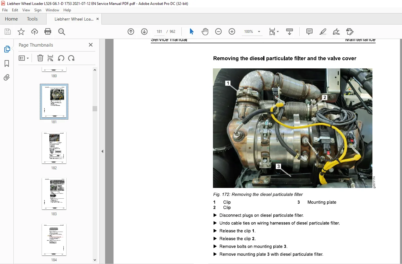
030.4.4.20 Cleaning or changing the diesel particulate filter
Cooling system 030-87
030.4.5.1 Cooling system: Checking the coolant level
Contents Service manual
030.4.5.2 Coolant: checking anti-freeze and corrosion protec-
tion agent concentration.
1526-1753; 030-89
0304.53 Cleaning the cooling system
1526-1753; 030-97
0304.5.4 Cooling system: changing coolant
L526-1753; 030-98
030.4.6 Hydraulic components 030-101
030.4.6.1 Hydraulic tank: checking oil level
1526-1753; 030-101
0304.6.2 Hydraulic tank: Checking and cleaning the magnetic
rod
L526-1753; 030-103
030.4.6.3 Hydraulic tank: draining off condensate and sediment
1526-1753; 030-103
0304.6.4 Hydraulic tank: Changing the return suction filter
cartridge
1526-1753; 030-104
030.4.6.5 Hydraulic tank: Change the breather filter
L526-1753; 030-105
030.4.6.6 Hydraulic tank: changing oil
1526-1753; 030-106
030.4.7 Steering system 030-109
030.4.7.1 Test steering
1526-1753; 030-109
0304.7.2 Steering cylinder: lubricating bearing
L526-1753; 030-109
030.4.8 Brake system 030-110
030.4.8.1 Testing service brake and parking brake
1526-1753; 030-110
0304.8.2 Service brake: checking brake plates for wear
L526-1753; 030-111
030.4.8.3 Parking brake: checking gap and wear on brake
linings
L526-1753; 030-113
030.4.9 Electrical system 030-119
030.4.9.1 Checking function of the lighting and horn
L526-1753; 030-119
030.4.9.2 Batteries: checking fluid levels and terminals
L526-1753; 030-120
0304.93 Use the control lever to change the travel direction
switch rocker and cap.
1526-1753; 030-122
030.4.9.4 Personnel detection: cleaning sensor
L526-1753; 030-124
copyright © Liebher-Werk Bischofshofen GmbH 2021
14 LIEBHERR 1526-1753
LBH/M2261289/04/211-20210712_103358/en
030.4.10.1 Transmission: checking oil level
1526-1753; 030-124
030.4.10.2 Transmission: changing oil
L526-1753; 030-125
030.4.11 Axles and drive shafts 030-127
030.4.11.1 Axle: checking oil levels
1526-1753; 030-127
030.4.11.2 Changing the axle oil
L 526-1753; 030-128
030.4.11.3 Front axle: Checking the tightening torque of the
fastening bolts
L 526-1753; 030-130
030.4.11.4 Checking the drive shaft
1526-1753; 030-131
030.4.11.5 Tyres: checking tyre pressure
1526-1753; 030-132
030.4.11.6 Checking the wheel tightness
L526-1753; 030-132
030.4.12 Steel parts of the basic machine 030-133
030.4.12.1 Lubricating the articulation bearing and the rear axle
oscillating bearing
1526-1753; 030-133
030.4.12.2 Service hatches: cleaning and maintaining seals
L526-1753; 030-134
030.4.13 Working attachment 030-134
030.4.13.1 Lubricating lift arms and working attachment
1526-1753; 030-134
030.4.13.2 Lift arms: checking bucket bearing bushings
L526-1753; 030-136
030.4.13.3 Checking lift arm bucket stops
L526-1753; 030-137
030.4.13.4 Scoop: Check teeth or undercut blade for wear and
replace if necessary
1526-1753; 030-138
030.4.13.5 Quick coupler: lubricating and testing bearings.
L526-1753; 030-141
030.4.13.6 Cleaning LIKUFIX hydraulic coupling
1526-1753; 030-141
030.4.13.7 High dump bucket: lubricating bearing
L 526-1753; 030-142
0304.14 Operator’s cab, heating and air conditioning 030-142
Contents Service manual
030.4.14.1 Operator’s cab: cleaning fresh and recirculated air
filters
L526-1753; 030-142
030.4.14.2 Operator’s cab: changing fresh air filter and recircu-
lated air filters
L526-1753; 030-144
030.4.14.3 Safety belt: checking condition and function
L526-1753; 030-146
030.4.144 Windscreen washer system: testing
L526-1753; 030-147
030.4.14.5 Windscreen washer system: filling windscreen
washer fluid
1526-1753; 030-147
030.4.14.6 Comfort safety door: lubricating lifting hinge
L526-1753; 030-148
030.4.14.7 Operator’s cab: lubricating locking mechanism and
cylinder with penetrating oil
1526-1753; 030-148
030.4.14.8 Operator’s cab: cleaning and maintaining seals
1526-1753; 030-149
030.4.14.9 Checking the indicator bead in the air conditioning
dryer-collector unit
L526-1753; 030-150
0304.14.10 Heating and air conditioning unit: testing function
1526-1753; 030-150
030.4.15 Lubrication system 030-152
030.4.15.1 Central lubrication system: checking level in grease
reservoir
L526-1753; 030-152
030.4.15.2 Central lubrication system: checking pipes, hoses
and lubrication points for leaks and damage.
1526-1753; 030-153
030.4.15.3 Central lubrication system: checking lubrication of
bearings
L526-1753; 030-154
030.5 Testing and adjustment checklist
L526-1753; 030-155
030.6 Testing and adjustment tasks 030-162
030.6.1 Safety precautions
L526-1753; 030-162
030.6.2 Overall machine 030-162
030.6.2.1 Preparing for adjustment procedures
1526-1753; 030-162
0306.2.2 Hydraulic oil and coolant: operating temperature
L526-1753; 030-164
030.6.3 Drive group 030-165
copyright © Liebher-Werk Bischofshofen GmbH 2021
16 LIEBHERR 526-1753
LBH/M2261289/04/211-20210712_103358/en
030.6.3.2 Diesel engine speed
Cooling system 030-167
030.6.4.1 Fan speed proportional solenoid valve
Working hydraulics 030-169
030.6.5.1 Multi-lever control (option): calibration
030.6.5.2 Calibrating working hydraulics angle sensors
030.6.5.3 Proportional solenoids in control valve block: calibra-
030.6.5.4 Working pump: flow regulator (standby pressure)
030.6.5.5 Working pump flow regulator (differential pressure)
030.6.5.6 Z-bar kinematics control valve block: secondary pres-
030.6.5.7 Z kinematics control valve block: secondary pressure
030.6.5.8 Control valve block: working hydraulics LS pressure
030.6.5.9 Stabilisation module (option), cut-off function
030.6.5.10 Ride control hydro accumulator (option): nitrogen
Hydraulic components 030-188
030.6.6.1 Hydro accumulator: checking and topping up
030.6.6.2 Checking the hydraulic lines for damage
Travel hydraulics 030-194
030.6.7.1 Travel pump high pressure sensor B45: Deviation
030.6.7.2 Travel pump replenishing pressure relief valve
Contents
0306.7.4 Travel pump: pressure cut-off
030.6.7.5 Travel pump: manual block curve calibration
030.6.7.6 Travel pump: automatic block curve calibration
030.6.7.7 Travel motor 1: start of regulation
030.6.7.8 Travel motor 2: automatic calibration
030.6.7.9 Diesel engine: Performance
Steering system 030-207
030.6.8.1 Joystick for joystick steering (option): calibration
030.6.8.2 Angle sensor for articulation angle (option): calibra-
030.6.8.3 Angle sensor for articulation angle (option): calibra-
0306.8.4 Control block for joystick steering (option): calibration
030.6.8.5 Control valve block: Steering system LS pressure
030.6.8.6 Steering damper hydro accumulator nitrogen filling
0306.8.7 Control block for joystick steering: determining instal-
L526-1753; 030-214
0306.9.2 Compact brake valve hydro accumulator charging
030.6.9.3 Service brake pressure
0306.9.4 Service brake hydro accumulator capacity
Electrical system 030-220
LBH/M2261289/04/211-20210712_103358/en
030.6.10.2 Central control unit (Master5): software update
030.6.10.3 Central control unit (Master5): resetting to factory
030.6.10.4 Central control unit (Master5): connecting Sculi diag-
030.6.10.5 Central control unit (Master5): connecting LiFT func-
030.6.10.6 Addressing CAN module and checking system infor-
Gearbox 030-234
030.6.11.1 Proportional solenoid for clutch: calibration
030.6.11.2 Rapid draining phase: calibration
030.6.11.3 Transmission hydraulics: Hydraulic oil adjustment
Axles and drive shafts 030-237
030.6.12.1 Tyres: setting radius
Working attachment 030-238
030.6.13.1 Working attachment: calibration (from software
030.6.13.2 Valve block for quick coupler (option): pressure
030.6.13.3 Parameters for lift arm geometry
030.6.13.4 Working attachment: freedom of movement
030.6.13.5 Working attachment: automatic return of 1st addi-
Operator’s cab, heating and air conditioning 030-242
030.6.14.1 Checking pressure and temperature conditions of air
030.6.14.2 Display (Display5): Check IP addresses
Contents
ware
L526-1753; 030-244
030.6.15 Options 030-245
030.6.15.1 LiDAT: connecting to LIDAT module
1526-1753; 030-245
030.6.15.2 LiDAT: software update for LIDAT module
L526-1753; 030-247
030.6.15.3 LiDAT: creating report and snapshot
1526-1753; 030-249
0306.154 Skyview 360°: calibration
L526-1753; 030-252
030.6.15.5 Personnel detection: transmitting configuration files
L526-1753; 030-259
030.6.15.6 Tyre pressure monitoring: changing and program-
ming pressure sensor
L526-1753; 030-265
040 Drive group 040-1
040.1 Engine 040-2
040.1.1 Diesel engine overview
L526-1753; 040-2
040.1.2 Electrical components of diesel engine
1526-1753; 040-6
040.1.3 Fuel system 040-16
040.1.3.1 Overview of fuel system
L526-1753; 040-16
040.1.3.2 Fuel level sensor
1526-1753; 040-17
040.1.3.3 Fuel pre-filter
L526-1753; 040-20
040.1.3.4 Fuel fine filter
L526-1753; 040-21
040.1.4 Air filter system 040-21
040.1.4.1 Air filter
1526-1753; 040-22
040.1.5 Exhaust system 040-22
040.1.5.1 Overview of exhaust system
L526-1753; 040-23
040.1.5.2 Diesel particulate filter (DPF): overview
1526-1753; 040-27
040.1.5.3 SCR system
L526-1753; 040-31
copyright © Liebher-Werk Bischofshofen GmbH 2021
20 LIEBHERR 1526-1753
Service manual
040.1.5.5 Diesel exhaust fluid pre-filter
1526-1753; 040-36
040.2 Clutch
L526-1753; 040-37
050 Cooling system 050-1
050.1 Overview of cooling system
1526-1753; 050-2
050.2 Cooling system hydraulics 050-3
0502.1 Overview of cooling system hydraulics
L526-1753/0-60945; 050-3
050.2.2 Overview of cooling system hydraulics
L526-1753/60946-; 050-7
050.2.3 Fan pump
L526-1753; 050-10
050.24 Fan motor
L526-1753/0-60945; 050-11
050.2.5 Fan motor
L526-1753/60946-; 050-13
050.3 Cooling system electronics 050-15
050.3.1 General overview of electronic control system
L526-1753; 050-15
050.3.2 Temperature sensor for coolant
L526-1753; 050-18
050.3.3 Hydraulic oil temperature sensor
L526-1753; 050-20
050.3.4 Temperature sensor for charge air
L526-1753; 050-21
050.4 Cooler 050-23
0504.1 Cooler unit
L526-1753; 050-23
2 050.5 Reversible fan drive 050-24
o 050.5.1 Overview of reversible fan drive
2 L526-1753; 050-24
2 0505.2 Fan motor for reversible fan drive
2 L526-1753; 050-27
3 060 Working hydraulics 060-1
060.1 Overview of Z-bar kinematics working hydraulics
1526-1753; 060-2
copyright ® Liebherr-Werk Bischofshofen GmbH 2021
1526-1753 LIEBHERR 2
Contents Service manual
080.2 Overview of the P kinematics working hydraulics
L526-1753; 060-10
060.3 Working pump
L526-1753; 060-14
060.4 Control block for Z-bar kinematics
L526-1753; 060-22
060.5 Control block for P-kinematics
L526-1753; 060-31
060.6 Pilot control 060-38
060.6.1 Pilot pressure for solenoid valve
1526-1753; 060-38
060.7 Ride control 060-40
060.7.1 Overview of ride control system
L526-1753; 060-40
060.7.2 Stabilisation module
1526-1753; 060-43
060.8 Electronics of the working hydraulics 060-46
060.8.1 Overview of electrical controls the working hydraulics
L526-1753; 060-46
060.8.2 Working hydraulics angle sensors
1526-1753; 060-48
060.8.3 Pressure sensors for lift cylinders and tilt cylinders
L526-1753; 060-51
060.9 Pipe break protection 060-53
060.9.1 Pipe break protection: overview
1526-1753; 060-53
060.9.2 Valve block for pipe break protection
1526-1753; 060-55
060.9.3 Solenoid valve for release of the ride control
1526-1753; 060-56
070 Travel hydraulics 070-1
070.1 Overview of travel hydraulics
1526-1753; 070-2
070.2 Travel pump
L526-1753; 070-7
070.3 Travel motors 070-22
070.3.1 Overview of the travel motors
L526-1753; 070-22
070.3.2 Travel motor 1
1526-1753; 070-24
070.3.3 Travel motor 2
L526-1753; 070-32
copyright © Liebher-Werk Bischofshofen GmbH 2021
22 LIEBHERR 1526-1753
LBH/M2261289/04/211-20210712_103358/en
080.1 Hydraulic system: overview
1526-1753; 080-2
080.2 Hydraulic tank 080-5
080.2.1 Overview of hydraulic tank
L 526-1753; 080-5
080.2.2 Return suction filter
L526-1753; 080-8
0802.3 Breather filter
L526-1753; 080-13
090 Steering system 090-1
090.1 Steering system overview
1526-1753; 090-3
090.2 Servostat
1526-1753; 090-7
090.3 Emergency steering 090-10
090.3.1 Emergency steering overview
L526-1753; 090-10
090.3.2 Emergency steering pump
L526-1753; 090-13
090.3.3 Emergency steering electronics 090-14
090.3.3.1 Overview of electrical controls of emergency steering
system
L 526-1753; 090-15
090.3.3.2 Emergency steering pressure switch
1526-1753; 090-19
090.3.3.3 Emergency steering check pressure switch
1526-1753; 090-20
090.4 Joystick steering 090-22
090.4.1 Joystick steering: overview (combined with steering wheel steering)
L526-1753; 090-22
0904.2 Joystick steering: overview (without steering wheel steering)
1526-1753; 090-28
090.4.3 Joystick steering control block
L526-1753; 090-32
0904.4 Joystick steering electrical system 090-37
090.4.4.1 Electronic control unit for joystick steering: overview
L 526-1753; 090-37
090.44.2 Joystick with position tracking
1526-1753; 090-44
090.5 2in1 steering 090-46
Contents
L526-1753; 090-46
090.5.2 Servostat for 2in1 steering
1526-1753; 090-50
100 Brake system 100-1
100.1 Overview of brake system
L526-1753; 100-2
100.2 Service brake and parking brake 100-7
100.2.1 Brake pump
1526-1753; 100-7
100.2.2 Compact brake valve
L526-1753; 100-8
100.3 Parking brake 100-16
100.3.1 Parking brake
1526-1753; 100-16
Electrical system 110-1
110.1 Overview of electrical system
L526-1753; 110-2
110.2 Circuit diagrams
L526-1753; 110-6
110.3 Electronic control unit 110-8
110.3.1 General overview of electronic control system
L526-1753; 110-8
110.3.2 Central control unit (Master5-Premium)
1526-1753; 110-10
110.3.3 Modules 110-13
110.3.3.1 Compact modules: overview
L526-1753; 110-13
110.3.3.2 Compact module
1526-1753; 110-15
110.4 Electrical components of the driver’s cab 110-21
110.4.1 Fuse and relay boards
L526-1753; 110-21
110.4.2 Door contact switch
1526-1753; 110-25
110.5 Electrical components in the rear section 110-26
110.5.1 Battery installation
1526-1753; 110-26
110.6 Rear area monitoring with camera 110-28
LBH/M2261289/04/211-20210712_103358/en
L526-1753; 110-28
1106.2 Camera
L526-1753; 110-28
120 Gearbox 120-1
120.1 Overview of the transmission
1526-1753; 120-2
120.2 Transmission hydraulics 120-6
120.2.1 Overview of transmission hydraulics
L526-1753; 120-6
120.2.2 Gear shifting proportional solenoid valve
L526-1753; 120-9
120.3 Transmission electronics 120-11
120.3.1 Overview of electrical control system of transmission
L526-1753; 120-11
120.3.2 Output speed sensor and travel motor 2 speed sensor
L526-1753; 120-14
130 Axles and drive shafts 130-1
130.1 Axles 130-2
130.1.1 Front axle
L526-1753; 130-2
130.1.2 Rear axle
L526-1753; 130-9
130.2 Cardan shafts 130-10
130.2.1 Drive shaft
L526-1753; 130-10
140 Steel parts of the basic machine 140-1
140.1 Vehicle frame 140-2
140.1.1 Articulation bearing
L526-1753; 140-2
140.1.2 Articulation lock
L526-1753; 140-3
150 Working attachment 150-1
150.1 Lift arms for Z kinematics 150-2
160.1.1 Lift arms for Z kinematics
L526-1753; 150-2
150.2 Lift arms for P kinematics 150-4
copyright ® Liebherr-Werk Bischofshofen GmbH 2021
1526-1753 LIEBHERR 25
Contents
L 526-1753; 150-4
150.3 Quick coupler 150-6
150.3.1 Quick coupler hydraulics 150-6
150.3.1.1 Overview of quick coupler hydraulics
L526-1753; 150-6
160.3.1.2 Valve block for quick coupler
1526-1753; 150-9
160.3.2 Quick coupler electrics 150-11
1560.3.2.1 Quick coupler electric control unit
L526-1753; 150-11
160 Operator’s cab, heating and air conditioning 160-1
160.1 Overview of operator’s cab, heating and air conditioning unit
1526-1753; 160-2
160.2 Display and control elements 160-4
160.2.1 Display (Display5)
L526-1753; 160-4
160.2.2 Control lever
1526-1753; 160-9
160.2.3 Accelerator pedal
1526-1753; 160-11
160.3 Heating, ventilation, air conditioning 160-13
160.3.1 Overview of heating, ventilation and air conditioning system
1526-1753; 160-13
160.3.2 Heating and air conditioning unit 160-17
160.3.2.1 Heating and air conditioning unit
L526-1753; 160-18
160.3.2.2 Blower
1526-1753; 160-22
160.3.3 Air conditioning controller
L 526-1753; 160-23
160.4 Air conditioning 160-26
160.4.1 Basic function of the air conditioning unit
L526-1753; 160-26
160.4.2 Air conditioning compressor
L 526-1753; 160-27
160.4.3 Condenser
1526-1753; 160-28
160.4.4 Dryer
1526-1753; 160-29
160.4.5 Air conditioning pressure switch
L526-1753; 160-30
170.1 Liebherr automatic central lubrication system 170-2
170.11 Liebherr automatic central lubrication system: overview
L 526-1753; 170-2
170.1.2 Liebherr central lubrication pump
L 526-1753; 170-8
190 Options 190-1
190.1 LiDAT 190-2
180.1.1 Overview of LIDAT
L526-1753; 190-2
190.1.2 LiDAT on machine
L526-1753; 190-4
190.1.3 LiDAT module (LiTU3)
1526-1753; 190-5
190.2 Liebherr weighing device with Truck Payload Assist
1526-1753; 190-11
190.3 Skyview 360° 190-13
190.3.1 Skyview 360°: complete overview
L 526-1753; 190-13
190.3.2 Skyview 360° on machine
L526-1753; 190-17
190.4 Personnel detection
L526-1753; 190-18
190.5 Elimination of steering-column switch 190-22
190.5.1 Elimination of steering-column switch: overview
1526-1753; 190-22
190.5.2 Additional controller (HY-TTC-30S)
L526-1753; 190-24
200 Diagnosis 200-1
200.1 Malfunctions 200-2
200.1.1 Warning symbols 200-2
200.1.2 SCR system warning symbols 200-3
200.1.3 Service code indicator in the display 200-3
200.2 Troubleshooting 200-5
200.2.1 Changing fuses 200-5
200.2.1.1 Fuses on fuse board A4 in the operator’s cab 200-5
200.2.1.2 Fuses on fuse board Adb in the operator’s cab 200-8
200.2.1.3 Fuses in the right ballast weight 200-9
Need help? Contact: [email protected]
IMAGES PREVIEW OF THE MANUAL:
PLEASE NOTE:
- This is the SAME manual used by the dealers to troubleshoot any faults in your vehicle. This can be yours in 2 minutes after the payment is made.
- Contact us at [email protected] should you have any queries before your purchase or that you need any other service / repair / parts operators manual.
S.V