Liebherr L 542 1269 Wheel Loader Service Manual – PDF DOWNLOAD
Original price was: $89.95.$32.95Current price is: $32.95.
Liebherr L 542 1269 Wheel Loader Service Manual – PDF DOWNLOAD
Description
Liebherr L 542 1269 Wheel Loader Service Manual – PDF DOWNLOAD
FILE DETAILS:
Liebherr L 542 1269 Wheel Loader Service Manual – PDF DOWNLOAD
Language : English
Pages : 762
Downloadable : Yes
File Type : PDF
Size: 172 MB
DESCRIPTION:
Liebherr L 542 1269 Wheel Loader Service Manual – PDF DOWNLOAD
- This service manual is designed for trained specialist staff of the Liebherr organisation and their dealers.
- This service manual contains specialist knowledge for repairing Liebherr construc- tion machines. Basic specialist knowledge on electronics, hydraulics, mechanics and engine technology is not contained in this service manual. Therefore special- ized training and qualifications are necessary. Liebherr recommends participating in the Liebherr training program for construction machines.
In this service manual you will find information on:
- You will find information on controls and operation in the operator’s manual. Information on spare parts are in the spare parts catalogue. Please observe the local accident prevention laws.
- You can find information on repairs of machine parts in the service documentation under “Wheel loader – repair instructions”.
Introduction:
To ensure safe operation:
- Consult with the worksite manager about safety regulations at the place of use.
- Adhere to safety regulations at the place of use.
- Follow traffic regulations.
- Adhere to valid guidelines provided by insurers (for example, employers’ professional liability insurance companies, accident insurance, etc.).
- Avoid working methods that can endanger safety.
- Follow all intervals specified for recurrent checks and inspections as outlined in this operator’s manual.
1.2. Intended Use of Wheel Loader
The wheel loader is used to pick up, move, and dump the following materials:
- Soil
- Stones
- Broken rocks
- Bulk materials
This applies to a standard machine under normal operating conditions. Special applications are described in a separate options operator’s manual.
To ensure the intended use:
- Adhere to the operator’s manual.
- Follow maintenance intervals.
- Carry out inspection and maintenance tasks.
- Follow the specifications in the technical data.
- When using the machine on public roads, ensure it complies with applicable national regulations.
- Only lift loads with intended working attachments (fork prongs, crane boom), which must be properly fitted and functioning.
- Ensure that machines used underground (for mining and tunnel construction) are fitted with systems to reduce exhaust emissions (such as diesel particulate filters).
- Adhere to the requirements of each individual country for underground operation.
- For special uses, use special working attachments and, if necessary, special safety equipment.
- Exclusively mount and use special working attachments with approval and as per the stipulations of the manufacturer of the basic machine.
IMAGES PREVIEW OF THE MANUAL:
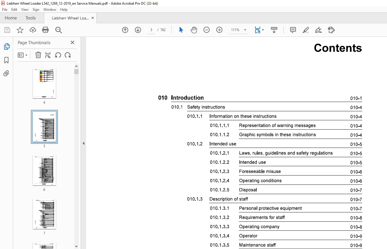
TABLE OF CONTENTS:
Liebherr L 542 1269 Wheel Loader Service Manual – PDF DOWNLOAD
010.1 Safety instructions 010-4
010.1.1 Information on these instructions 010-4
010.1.1.1 Representation of warning messages 010-4
010.1.1.2 Graphic symbols in these instructions 010-4
010.1.2 Intended use 010-5
010.1.2.1 Laws, rules, guidelines and safety regulations 010-5
010.1.2.2 Intended use 010-5
010.1.2.3 Foreseeable misuse 010-6
010.1.2.4 Operating conditions 010-6
010.1.2.5 Disposal 010-7
010.1.3 Description of staff 010-7
010.1.3.1 Personal protective equipment 010-7
010.1.3.2 Requirements for staff 010-8
010.1.3.3 Operating company 010-8
010.1.3.4 Operator 010-9
010.1.3.5 Maintenance staff 010-9
010.1.3.6 Refrigeration technician 010-10
010.1.3.7 Slinger 010-11
010.1.3.8 Spotter 010-12
0101.4 Protective devices on the machine 010-12
010.1.4.1 Operator’s cab 010-12
010.1.4.2 Roll over protective structure (ROPS) 010-13
010.1.4.3 Falling object protective structures (FOPS) 010-13
0101.5 Emergency equipment on the machine 010-13
010.1.5.1 Emergency exit (standard) 010-13
010.1.5.2 Fire extinguisher (option) 010-14
010.1.6 Safe operation 010-14
010.1.6.1 Intoxicants 010-14
010.1.6.3 Transporting machine 010-15
010.1.6.4 Access to machine 010-15
010.1.6.5 Machine danger zone 010-16
010.1.6.6 Visibility 010-16
010.1.6.7 Protection against vibration 010-17
010.1.6.8 Operation of machine 010-18
010.1.7 Safe maintenance 010-21
010.1.7.1 Spare parts 010-21
010.1.7.2 Heavy parts 010-21
010.1.7.3 Regular checks 010-22
010.1.8 Modifications to the machine 010-22
010.1.8.1 Modifications, add-ons and retrofittings 010-22
Special tools for maintenance and repair work 010-23
010.21 Special tools, general 010-23
010.2.2 Special tools for the diesel engine 010-24
010.2.3 Special tools for Z kinematics lift cylinder 010-24
010.2.4 Special tools for Z kinematics tilt cylinder 010-25
010.2.5 Special tools for P kinematics lift cylinder 010-25
010.2.6 Special tools for P kinematics tilt cylinder 010-25
010.2.7 Special tools for steering cylinders 010-26
010.2.8 Special tools for the electrical system 010-26
010.2.9 Special tools for axles 010-26
010.2.10 Special tools for the air conditioning system 010-27
010.2.11 Special tools for cab glazing 010-27
010.2.12 Special tools for the central lubrication system (Liebherr) 010-28
010.2.13 Special tools for the central lubrication system (Groeneveld) 010-28
010.4.1 General information 010-37
010.4.2 Machine out of service for an unknown period of time 010-37
0104.3 Putting the machine out of service 010-38
010.4.3.2 Out of service for up to 12 months 010-39
010.4.3.3 Out of service for longer than 12 months 010-40
010.44 Putting back into service 010-40
010.4.4.1 After being out of service for 2 months 010-40
010.4.4.2 After being out of service for 12 months 010-41
020.1 Drive group 020-5
0201.1 Engine
L542-1269/24755-; 020-5
020.1.2 Fuel tank
L542-1269/24755-; 020-6
020.1.2.1 Fuel tank – plastic version 020-6
020.1.2.2 Steel fuel tank (optional) 020-6
020.1.3 Fuel level sensor
L542-1269/24755-; 020-6
020.14 Fuel pre-filter
1 542-1269/24755-; 020-7
020.1.5 Fuel fine filter
L542-1269/24755-; 020-7
020.1.6 Air mass sensor vacuum switching point
L542-1269/24755-; 020-7
020.1.7 Clutch
L542-1269/24755-; 020-7
020.2 Cooling system 020-8
0202.1 Water cooler
L542-1269/24755-; 020-8
020.2.2 Fan gear pump
L542-1269/24755-; 020-8
020.2.3 Fan gear motor
L542-1269/24755-; 020-8
020.3 Working hydraulics 020-9
020.3.1 Working hydraulics pump
L542-1269/24755-; 020-9
020.3.3 P kinematics control valve block
020.3.4 Pilot control hydro accumulator
020.3.5 Stabilisation module (optional)
020.3.6 Ride control hydro accumulator (optional)
020.3.7 Z kinematics lift cylinder
020.3.8 Z kinematics tilt cylinder
020.3.9 P kinematics lift cylinder
020.3.10 P kinematics tilt cylinder
Travel hydraulics 020-13
020.4.1 Travel pump
020.4.2 Travel motor 1
020.4.3 Travel motor 2
Hydraulic components 020-15
020.5.1 Filter unit
020.5.2 Breather filter
Steering system 020-16
020.6.1 Servostat
020.6.2 Steering cylinder
020.6.3 Emergency steering pump
020.6.4 Emergency steering pressure switch B3
020.6.5 Emergency steering check pressure switch B3a
Brake system 020-18
020.7.1 Service brake hydro accumulator
L542-1269/24755-; 020-18
020.7.3 Accumulator charge pressure switch B19
L542-1269/24755-; 020-18
020.7.4 Disc brake
L542-1269/24755-; 020-18
020.7.5 Parking brake hydro accumulator
L542-1269/24755-; 020-19
020.8 Electrical system 020-20
020.8.1 Central control unit (Master 4)
L542-1269/24755-; 020-20
020.8.2 Input module
L542-1269/24755-; 020-20
020.8.3 Output module
L542-1269/24755-; 020-20
020.84 Battery
L542-1269/24755-; 020-21
020.8.5 Voltage transformer
L542-1269/24755-; 020-21
020.9 Gearbox 020-22
020.9.1 Transmission
L542-1269/24755-; 020-22
020.9.2 Output speed sensor B1 and travel motor 2 speed sensor B2
L542-1269/24755-; 020-22
020.10 Axles and drive shafts 020-23
020.10.1 Front axle
L542-1269/24755-; 020-23
020.10.2 Rear axle
L542-1269/24755-; 020-23
020.10.3 Cardan shaft
L542-1269/24755-; 020-24
020.11 Steel parts of the basic machine 020-25
020.11.1 Ballast weight
1 542-1269/24755-; 020-25
020.12 Operator’s cab, heating and air conditioning 020-26
020.12.1.1 Air conditioning compressor 020-26
020.12.2 Dryer
1 542-1269/24755-; 020-26
020.12.3 Pressure switches
L542-1269/24755-; 020-26
020.12.4 Anti-icing temperature sensor
L542-1269/24755-; 020-26
020.13 Lubrication system 020-28
L542-1269/24755-; 020-28
020.13.1.1 Central lubrication pump 020-28
020.13.2 Progressive distributor
L542-1269/24755~; 020-28
020.13.21 MX-F 020-28
020.13.2.2 MX-F 25 020-28
020.13.2.3 MX-F 45 020-29
020.13.24 MXF75 020-29
020.13.2.56 MX-F105 020-29
030 Maintenance 030-1
030.1 Maintenance and inspection schedule 030-9
030.2 Filling quantities and lubrication chart 030-14
030.2.1 Recommended lubricants
1 542-1269/24755-; 030-14
030.22 Recommended operating fluids
1542-1269/24755-40516; 030-15
030.23 Recommended operating fluids
L542-1269/40517-; 030-15
030.3 Lubricants and fuels 030-16
030.3.1 General information on lubricants and fuels 030-16
030.3.1.1 General questions 030-16
030.3.1.2 Safety data sheets 030-16
030.3.1.3 Technical data sheets 030-16
030.3.1.4 Specific Liebherr standards 030-16
030.3.2 General information on changing lubricants and fuels 030-16
030.3.3 Converting hydraulic system from mineral oils to biodegradable
hydraulic fluids 030-17
030.3.4 Diesel fuels
1542-1269/24755~; 030-17
030.3.4.1 Specification 030-17
030.3.4.2 Sulphur content of the diesel fuel, lubricity 030-17
030.3.43 Diesel fuel at low temperatures (winter operation) 030-18
030.3.4.4 Flow improvers at low temperatures 030-18
030.3.5 Lubricating oils for diesel engines
030.3.5.1 Lubricating oil quality 030-18
030.3.5.2 Lubricating oil viscosity 030-19
030.3.5.3 Complicating factors affect the oil change 030-19
030.3.6 Refrigerant
1542-1269; 030-20
030.3.7 Coolants for diesel engines
L542-1269/24755-40516; 030-20
030.3.7.1 General recommendations 030-20
030.3.7.2 Water (fresh water) 030-20
030.3.7.3 Coolant mixing ratio 030-21
030.3.7.4 Permissible antifreeze and corrosion inhibitors 030-21
030.3.7.5 Corrosion inhibitors without antifreeze 030-22
030.3.8 Coolants for diesel engines
1.542-1269/40517-; 030-22
030.3.8.1 General recommendations 030-22
030.3.8.2 Water (fresh water) 030-23
030.3.8.3 Coolant – Mixing ration 030-23
030.3.8.4 Approved antifreeze and corrosion inhibitors 030-23
030.3.8.5 Permissible premixed antifreeze/corrosion inhibitors 030-24
030.3.8.6 Corrosion inhibitors without antifreeze 030-24
030.3.9 Hydraulic oil
L542-1269/24755-; 030-25
030.3.9.1 Liebherr hydraulic oil 030-25
030.3.9.2 Using engine oil as hydraulic oil 030-25
030.3.9.3 Warming up 030-26
030.3.9.4 Biodegradable hydraulic oils 030-26
030.3.9.5 Changing the oil, analysing the oil, changing filters 030-27
030.3.10 Lubricating oils for transmissions
L542-1269/24755-; 030-28
030.3.11 Lubricating oils for axles
L542-1269/24755-; 030-29
030.3.12 Lubrication grease and other lubricants
1.542-1269/24755-; 030-30
030.3.12.1 Minimum quality requirements 030-30
030.3.12.2 Liebherr lubrication grease 030-30
030.4 Maintenance tasks 030-32
030.4.1 Safety precautions
1.542-1269/24755-; 030-32
0304.2 Preparatory tasks for maintenance 030-32
030.4.2.1 Maintenance positions
030.4.2.2 Opening the service accesses
L542-1269/24755-; 030-34
030.4.2.3 Turning off the battery main switch
1.542-1269/24755-; 030-36
030.4.3 Overall machine 030-36
030.4.3.1 Checking the machine for external damage
L542-1269/24755-24774; L542-1269/24775-; 030-36
030.4.3.2 Removing loose parts, dirt, ice and snow from the
machine
1.542-1269/24755-; 030-36
030.4.3.3 Cleaning the machine
L542-1269/24755-; 030-37
0304.3.4 Checking the machine for leaks
L542-1269/24755-; 030-38
030.4.3.5 Making sure the bolted connections are tight
L542-1269/24755~; 030-39
0304.36 Corrosion protection system for use with salt and arti-
ficial fertilisers (optional): Carrying out corrosion
protection
L542-1269/24755-; 030-39
0304.3.7 Oil analyses
L542-1269/24755-; 030-39
030.4.4 Drive group 030-45
030.4.4.1 Checking the engine oil level
1.542-1269/24755-; 030-45
0304.4.2 Changing the engine oil
L542-1269/24755-; 030-46
030.4.4.3 Changing the engine oil filter
1.542-1269/24755-; 030-47
0304.4.4 Checking the V-ribbed belt on the engine
1.542-1269/24755-; 030-48
030.445 Changing V-ribbed belt of diesel engine
L542-1269/24755-; 030-49
030.4.4.6 Checking the diesel engine valve clearance
L542-1269/24755-; 030-51
030.447 Diesel engine oil separator – changing filter cartridge
1.542-1269/24755-; 030-54
0304.4.8 Checking the bleeder filter of the crankcase
1.542-1269/24755-; 030-55
030.4.4.9 Checking the glow plugs
L542-1269/24755-; 030-56
030.4.4.10 Draining off condensate and sediment from the fuel
tank
1.542-1269/24755-; 030-58
L542-1269/24755-; 030-59
030.4.4.12 Changing the fuel pre-filter
1 542-1269/24755-; 030-60
030.4.4.13 Changing the fuel fine filter
1 542-1269/24755-; 030-61
030.4.4.14 Bleeding the fuel system
1 542-1269/24755-; 030-62
030.4.4.15 Cleaning the air filter service cover and dust
discharge valve
1. 542-1269/24755-; 030-63
030.4.4.16 Checking the air suction system for leaks and tight
fitting
1 542-1269/24755-; 030-65
030.4.4.17 Cleaning or changing the main filter element
1. 542-1269/24755-; 030-66
030.4.4.18 Changing the air filter safety element
1 542-1269/24755-; 030-69
030.4.4.19 Checking the exhaust system for leaks and tight
fitting
1 542-1269/24755-; 030-70
030.4.4.20 Cleaning or changing the diesel particulate filter
L542-1269/24755-; 030-71
0304.5 Cooling system 030-75
030.4.5.1 Checking the coolant level
1 542-1269/24755-; 030-75
030.4.5.2 Checking the coolant antifreeze and corrosion inhib-
itor concentration
L542-1269/24755-; 030-76
030.4.5.3 Cleaning the cooling system
1542-1269/24755-; 030-80
030.4.5.4 Changing the coolant
1 542-1269/24755-40516; 030-81
030.4.5.5 Changing the coolant
1 542-1269/40517-; 030-83
0304.6 Working hydraulics 030-85
030.4.6.1 Lubricating the solenoids, universal joints and
tappets on the pilot control unit
1 542-1269/24755-; 030-85
030.4.7 Hydraulic components 030-86
030.4.7.1 Checking the oil level in the hydraulic tank
1 542-1269/24755-; 030-86
030.4.7.2 Checking and cleaning the magnetic rod on the
hydraulic tank
1 542-1269/24755-35974; 030-87
030.4.7.4 Draining off condensate and sediment from the
030.4.7.5 Hydraulic tank – changing the return-suction filter
030.4.7.6 Changing the hydraulic tank return suction filter
0304.7.7 Changing the hydraulic tank breather filter
030.4.7.8 Changing the oil in the hydraulic system in accord-
Steering system 030-94
030.4.8.1 Testing the steering
030.4.8.2 Lubricating the bearing points on the steering cylin-
Brake system 030-96
030.4.9.1 Testing the service brake and parking brake
0304.9.2 Checking the service brake discs for wear
030.4.9.3 Checking gap and wear on parking brake linings
Electrical system 030-105
030.4.10.1 Checking the lights
0304.10.2 Checking the batteries, fluid level and terminals
030.4.10.3 Changing the travel direction rocker switch and cap
Gearbox 030-110
0304.11.1 Checking the transmission oil level
030.4.11.2 Changing the transmission oil
Axles and drive shafts 030-111
0304.12.1 Checking the axle oil levels
L542-1269/24755-; 030-112
030.4.12.3 Checking the tightening torque of the front axle
fastening bolts
1L542-1269/24755-; 030-114
030.4.124 Checking the cardan shafts
L542-1269/24755-; 030-115
030.4.12.5 Checking the tyre pressure
1542-1269/24755-; 030-115
030.4.126 Checking the wheel tightness (once after 50, 100 and
250 h)
1542-1269/24755-; 030-116
030.4.13 Steel parts of the basic machine 030-117
030.4.13.1 Lubricating the articulation bearing and the rear axle
oscillating bearing
L542-1269/24755-; 030-117
030.4.13.2 Covering – lubricating locks and hinges
1542-1269/24755-; 030-117
030.4.14 Working attachment 030-118
030.4.14.1 Lubricating lift arms and attached working attach-
ment
L542-1269/24755-; 030-118
030.4.14.2 Checking the lift arm bearing bushings
1542-1269/24755-; 030-119
030.4.14.3 Checking the lift arm bucket stops (Z kinematics)
L542-1269/24755-; 030-120
030.4.14.4 Lubricating and testing the quick-change device
1542-1269/24755-; 030-121
030.4.15 Operator’s cab, heating and air conditioning 030-122
030.4.15.1 Lubricating the elongated hole on the accelerator
pedal and checking the bearing
L542-1269/24755-27642, L 542-1269/27643-; 030-122
030.4.15.2 Cleaning the fresh and recirculated air filters
1542-1269/24755-; 030-123
030.4.15.3 Changing the fresh and recirculated air filters
L542-1269/24755-; 030-125
030.4.154 Checking the condition and function of the safety belt
L542-1269/24755-; 030-126
030.4.15.5 Checking and topping up the windscreen washer
reservoir
L542-1269/24755-; 030-126
030.4.15.6 Checking the seals on the driver’s cab
1L542-1269/24755-; 030-127
030.4.15.7 Checking the indicator bead in the air conditioning
dryer-collector unit
1L542-1269/24755-; 030-127
copyright ® Liebherr-Werk Bischofshofen GmbH 2019
542-1268 LIEBHERR 15
Contents
Lubrication system 030-129
030.4.16.1 Checking the lubrication system grease reservoir
030.4.16.2 Checking the pipes, hoses and lubrication points of
030.4.16.3 Checking whether metered quantities are adequate
tion system
L542-1269/24755-; 030-130
030.6 Testing and adjustment tasks 030-136
030.6.1 Safety precautions
1542-1269/24755-; 030-136
030.6.2 Overall machine 030-136
030.6.2.1 Preparatory tasks for testing and adjustment
1L542-1269/24755-; 030-136
030.6.2.2 Bringing the machine up to operating temperature
1.542-1269/24755-; 030-138
030.6.3 Drive group 030-139
030.6.3.1 Calibrating the pedals
L542-1269/24755-; 030-139
0306.3.2 Engine: Speed
1.542-1269/24755-; 030-139
030.6.3.3 Reading the diesel engine service files
L542-1269; 030-140
030.6.4 Cooling system 030-142
030.6.4.1 Fan gear motor proportional pressure relief valve
L542-1269/24755-; 030-142
030.6.5 Working hydraulics 030-145
030.6.5.1 Working hydraulics pump flow regulator (standby
pressure)
L542-1269/24755-; 030-145
030.6.5.2 Z kinematics control valve block secondary pressure
relief valves
1.542-1269/24755-; 030-146
0306.5.3 Working hydraulics LS pressure cut-off
1L542-1269/24755-; 030-148
030.6.5.4 P-kinematics control block for secondary pressure
L542-1269/24755-; 030-149
LBH/M1657128/10/211-20191203_081418/en
L542-1269/24755-; 030-151
030.6.5.6 Ride control hydro accumulator (optional), nitrogen
filling
1L542-1269/24755-; 030-151
030.6.5.7 Testing control valve block for leakage
L542-1269/24755-; 030-154
030.6.6 Hydraulic components 030-158
030.6.6.1 Checking the hydraulic lines for damage
1542-1269; 030-158
0306.7 Travel hydraulics 030-163
030.6.7.1 Travel pump replenishing pressure relief valve
L542-1269/24755-; 030-163
030.6.7.2 Travel pump high pressure relief valves
1542-1269/24755-; 030-164
030.6.7.3 Travel pump pressure cut-off
L542-1269/24755-; 030-167
030.6.7.4 Travel pump block curve calibration
L542-1269/24755-; 030-168
030.6.7.5 Travel motor 1 start of regulation
L542-1269/24755-; 030-170
030.6.7.6 Travel motor 2 automatic calibration
1542-1269/24755-; 030-171
030.6.7.7 Engine output
L542-1269/24755-; 030-172
0306.8 Steering system 030-174
030.6.8.1 Steering system LS pressure cut-off
1542-1269/24755-; 030-174
030.6.9 Brake system 030-175
030.6.9.1 Accumulator charge pressure switch shift pressure
1L542-1269/24755-; 030-175
030.6.9.2 Compact brake valve, hydro accumulator charging
function
1542-1269/24755-; 030-176
030.6.9.3 Service brake pressure
L542-1269/24755-; 030-177
030.6.9.4 Service brake hydro accumulator capacity
L542-1269/24755-; 030-177
030.6.10 Electrical system 030-179
030.6.10.1 Central control unit (Master4) Creating a Servicefile
1542-1269/24755-; 030-179
030.6.10.2 Central control unit (Master4): software update
L 542-1269; 030-182
copyright ® Liebherr-Werk Bischofshofen GmbH 2019
1542-1269 LIEBHERR 17
Contents
(Master4)
L542-1269/24755-; 030-185
030.6.10.4 Resetting the central control unit (Master4)
1.542-1269/24755-; 030-187
030.6.10.5 Testing the CAN line
L542-1269/24755-; 030-188
030.6.10.6 Addressing the CAN module and checking the
system information
L542-1269/24755-; 030-192
030.6.11 Gearbox 030-195
030.6.11.1 Automatic calibration of clutch proportional solenoid
valve
1L542-1269/24755-; 030-195
030.6.11.2 Hydraulic control system — hydraulic oil adjustment
L542-1269/24755-; 030-196
030.6.12 Operator’s cab, heating and air conditioning 030-196
0306.12.11 Adjusting the heating circuit pressure relief valve
L542-1269/24755-39419; 030-196
0306.12.2 Checking the pressure and temperature conditions of
the air conditioning unit
L542-1269/24755-; 030-197
030.6.12.3 Calibrating the display (Display4)
1.542-1269/24755-; 030-198
0306.12.4 Formatting the display and reinstalling the software
(Display4)
L542-1269/24755-; 030-200
030.6.13 Options 030-201
030.6.13.1 Checking the LiDAT connection status
1.542-1269/24755-; 030-201
0306.13.2 LiDAT: activating data transmission manually
L542-1269; 030-203
040 Drive group 040-1
040.1 Engine 040-2
040.1.1 Diesel engine overview
1 542-1269/24755-; 040-2
040.1.2 Fuel system 040-5
040.1.2.1 Overview of fuel system
L542-1269/24755-; 040-6
040.1.2.2 Fuel level sensor
1.542-1269/24755-; 040-7
040.1.2.3 Fuel pre-filter
L542-1269/24755-; 040-9
LBH/M1657128/10/211-20191203_081418/en
040.1.3 Air filter system 040-10
040.1.3.1 Overview of the air filter unit
L542-1269/24755-; 040-11
040.1.3.2 Air filter
L542-1269/24755-; 040-12
040.14 Exhaust system 040-12
040.1.4.1 Overview of the exhaust system
L542-1269/24755-; 040-13
040.1.4.2 Overview of the diesel particulate filter
L542-1269/24755-; 040-14
040.2 Clutch
1L542-1269/24755-; 040-20
050 Cooling system 050-1
050.1 Overview of the cooling system
L542-1269/24755-; 050-2
050.2 Cooling system hydraulics 050-4
0502.1 Overview of the hydraulics cooling system
L542-1269/24755-; 050-4
050.2.2 Fan gear pump
L542-1269/24755-; 050-6
050.2.3 Fan gear motor
1L542-1269/24755-; 050-7
050.3 Cooling system electronics 050-11
050.3.1 Electronic control system — general overview
L542-1269/24755-; 050-11
050.3.2 Coolant temperature sensor
L542-1269/24755-; 050-12
050.3.3 Hydraulic oil temperature sensor
L542-1269/24755-; 050-14
050.34 Charge air temperature sensor
L542-1269/24755-; 050-15
050.4 Cooler 050-17
0504.1 Water cooler
L542-1269/24755-; 050-17
0504.2 Hydraulic oil cooler
L542-1269/24755-; 050-18
050.4.3 Intercooler
L542-1269/24755-; 050-20
0504.4 Fuel cooler
L542-1269/24755-; 050-21
copyright ® Liebherr-Werk Bischofshofen GmbH 2019
1542-1269 LIEBHERR 19
Contents
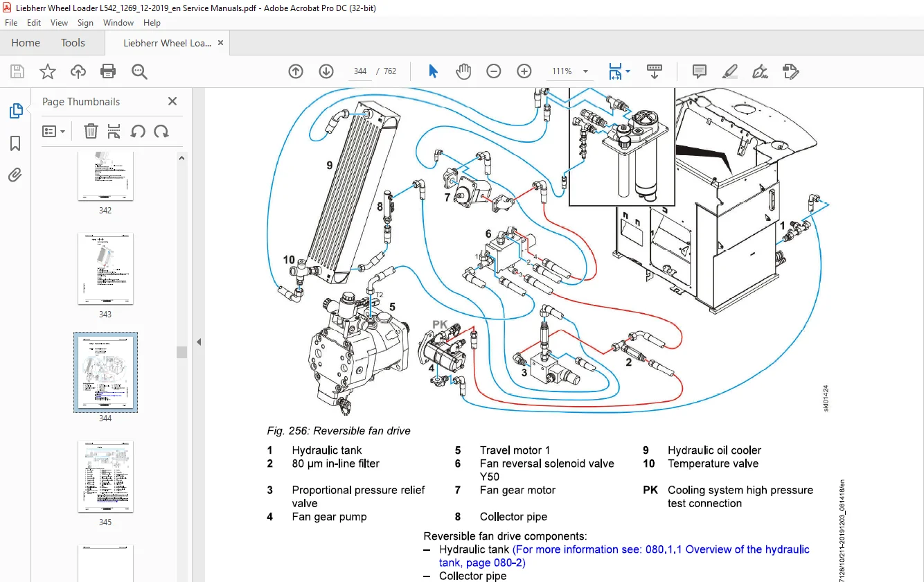
050.5.1 Reversible fan drive
1 542-1269/24755-; 050-22
060 Working hydraulics 060-1
060.1 Overview of z kinematics working hydraulics
L542-1269/24755-; 060-3
060.2 Overview of working hydraulics for p kinematics
1 542-1269/24755-; 060-8
060.3 Working hydraulics pump
L542-1269/24755-; 060-13
060.4 Control valve block for Z-bar kinematics
L542-1269/24755-; 060-17
060.5 Control valve block for P kinematics
L542-1269/24755-; 060-23
060.6 Pilot control 060-28
060.6.1 Overview of the pilot control unit
1542-1269/24755-; 060-28
060.6.2 Pilot control unit
1 542-1269/24755-; 060-29
060.6.3 Working hydraulics lockout solenoid valve
1 542-1269/24755-; 060-34
060.6.4 Pilot control hydro accumulator
1 542-1269/24755-; 060-35
060.7 Ride control 060-36
060.7.1 Ride control overview
1.542-1269/24755-; 060-36
060.7.2 Stabilisation module
1 542-1269/24755-; 060-37
060.7.3 Ride control hydro accumulator
1542-1269/24755-; 060-42
060.8 Hydraulic cylinders of the working hydraulics 060-43
060.8.1 Hydraulic cylinders for Z kinematics 060-43
060.8.1.1 Z kinematics lift cylinder
L542-1269/24755-; 060-43
060.8.1.2 Z kinematics tilt cylinder
1542-1269/24755-; 060-45
060.8.2 Hydraulic cylinders for P kinematics 060-46
060.8.2.1 P kinematics lift cylinder
1542-1269/24755-; 060-47
060.8.2.2 P kinematics tilt cylinder
1.542-1269/24755-; 060-48
LBH/M1657128/10/211-20191203_081418/en
070.1 Travel hydraulics overview
1.542-1269/24755-36291; 070-2
070.2 Travel hydraulics overview
1.542-1269/36292-; 070-7
070.3 Travel pump
L542-1269/24755-36291; 070-12
070.4 Travel pump
1.542-1269/36292-; 070-26
070.5 Travel motors 070-41
0705.1 Overview of the travel motors
L542-1269/24755-; 070-41
070.5.2 Travel motor 1
L542-1269/24755-; 070-43
070.5.3 Travel motor 2
L542-1269/24755-; 070-50
080 Hydraulic components 080-1
080.1 Hydraulic tank 080-2
080.1.1 Overview of the hydraulic tank
L542-1269/24755-; 080-2
080.1.2 Filter unit
L542-1269/24755-; 080-4
080.1.3 Breather filter
L542-1269/24755-; 080-9
090 Steering system 090-1
090.1 Steering system overview
1.542-1269/24755-35802; 090-2
090.2 Steering system overview
L542-1269/24755-35802; L542-1269/35803-; 090-6
090.3 Servostat
L542-1269/24755-; 090-10
090.4 Steering cylinder 090-14
090.4.1 Steering cylinder overview
L542-1269/24755-35802; 090-14
0904.2 Steering cylinder overview
L542-1269/35803-; 090-16
0904.3 Steering damper hydro accumulator
L542-1269/24755-35802; L542-1269/35803-; 090-18
090.5 Emergency steering 090-19
0905.1 Emergency steering overview
L542-1269/24755-; 090-19
copyright ® Liebherr-Werk Bischofshofen GmbH 2019
1542-1269 LIEBHERR 21
Contents Service manual
090.5.3 Emergency steering electronics 090-22
090.5.3.1 Overview of the electronic control system
L542-1269/24755-; 090-22
090.5.3.2 Emergency steering pressure switch
L542-1269/24755-; 090-23
090.5.3.3 Emergency steering check pressure switch
1542-1269/24755-; 090-24
090.54 Valve block
1542-1269/24755-; 090-25
100 Brake system 100-1
100.1 Overview of the brake system
L542-1269/24755-; 100-2
100.2 Service brake and parking brake 100-4
100.2.1 Brake system gear pump
1 542-1269/24755-; 100-4
100.2.2 Compact brake valve
1.542-1269/24755; 100-5
100.3 Service brake 100-12
100.3.1 Overview of the service brake
1 542-1269/24755-; 100-12
100.3.2 Service brake hydro accumulator
1 542-1269/24755-; 100-15
100.3.3 Brake light pressure switch
L542-1269/24755-; 100-16
100.3.4 Accumulator charge pressure switch
1542-1269/24755-; 100-17
100.4 Parking brake 100-18
100.4.1 Overview of the parking brake
1 542-1269/24755-; 100-18
100.4.2 Disc brake
1 542-1269/24755-; 100-21
100.4.3 Parking brake hydro accumulator
1542-1269/24755-; 100-22
110 Electrical system 110-1
110.1 Overview of the electrical system
L542-1269/24755-; 110-2
110.2 Lighting
L542-1269/24755-; 110-7
LBH/M1657128/10/211-20191203_081418/en
L542-1269/24755-; 110-9
110.4 Electronic control unit 110-11
110.4.1 Overview of the electronic control system
L542-1269/24755-; 110-11
110.4.2 Central control unit (Master4)
L542-1269/24755-; 110-14
110.4.3 Modules 110-18
110.4.3.1 Overview of the module
L542-1269/24755-; 110-18
110.4.3.2 Input modules
L542-1269/24755-; 110-20
110.4.3.3 Output modules
L542-1269/24755-; 110-22
110.5 Electrical components of the driver’s cab 110-25
110.5.1 Overview of electrical components in the driver’s cab
L542-1269/24755-; 110-25
110.5.2 Fuse and relay board
L542-1269/24755-; 110-26
110.6 Electrical components in the rear section 110-30
110.6.1 Battery installation
1L542-1269/24755-36021; 110-30
110.6.2 Battery installation
L542-1269/36022-; 110-32
120 Gearbox 120-1
120.1 Overview of the transmission
1.542-1269/24755-; 120-2
120.2 Mechanical transmission
1L542-1269/24755-; 120-3
120.3 Transmission hydraulics 120-9
120.3.1 Overview of the hydraulic control system
L542-1269/24755-; 120-9
120.4 Transmission electronics 120-13
120.4.1 Overview of the electronic control system
L542-1269/24755-; 120-13
120.4.2 Output speed sensor and travel motor 2 speed sensor
L542-1269/24755-; 120-14
130 Axles and drive shafts 130-1
130.1 Axles 130-2
copyright ® Liebherr-Werk Bischofshofen GmbH 2019
1542-1269 LIEBHERR 23
Contents
130.1.2 Rear axle
1542-1269/24755-; 130-7
130.2 Cardan shafts 130-8
130.2.1 Cardan shaft
L542-1269/24755-; 130-8
140 Steel parts of the basic machine 140-1
140.1 Vehicle frame 140-2
140.1.1 Articulation bearing
1542-1269/24755-; 140-2
140.1.2 Articulation lock
L542-1269/24755-; 140-3
150 Working attachment 150-1
150.1 Lift arms for Z kinematics 150-2
150.1.1 Z kinematics lift arms
L542-1269/24755-; 150-2
1560.1.2 Pin bearing 150-2
150.1.2.1 Z kinematics standard pin bearing
L542-1269/24755-; 150-3
160.2 Lift arms for P kinematics 150-4
160.2.1 P kinematics lift arm
1542-1269/24755-; 150-4
160.3 Quick coupler 150-5
1560.3.1 Z kinematics quick coupler
L542-1269/24755-; 150-5
150.3.2 P kinematics quick coupler
L542-1269/24755-; 150-8
160 Operator’s cab, heating and air conditioning 160-1
160.1 Overview of the cab, heating and air conditioning unit
L542-1269/24755-; 160-3
160.2 Display and control elements 160-5
160.2.1 Electrical components in the control panel 160-5
160.2.1.1 Overview of electrical components in the control
panel
1.542-1269/24755-; 160-5
160.2.1.2 Control unit for main functions
L542-1269/24755-; 160-5
LBH/M1657128/10/211-20191203_081418/en
160.2.2 Display
L542-1269/24755-; 160-9
160.2.3 Touch screen display
L542-1269/24755-; 160-11
160.24 Control lever
L542-1269/24755-; 160-13
160.3 Heating, ventilation, air conditioning 160-16
160.3.1 Overview of the heating, ventilation and air conditioning system
L542-1269/24755-; 160-16
160.3.2 Heating and air conditioning unit 160-21
160.3.2.1 Heating and air conditioning unit
L542-1269/24755-; 160-22
160.3.2.2 Blower
1 542-1269/24755-; 160-24
160.3.3 Heating/air conditioning electronics
L542-1269/24755-; 160-25
160.3.4 Heating circuit pressure relief valve
L542-1269/24755-39419; 160-26
160.3.5 Pressure relief valve for heating circuit
L542-1269/39420-; 160-28
160.4 Air conditioning 160-30
160.4.1 Basic function of the air conditioning unit
1L542-1269/24755-; 160-30
160.4.2 Air conditioning compressor
L542-1269/24755-; 160-31
160.4.3 Condenser
L542-1269/24755-; 160-32
160.44 Dryer
L542-1269/24755-; 160-33
160.4.5 Air conditioning pressure switch
1 542-1269/24755-; 160-35
160.4.6 Evaporator
L542-1269/24755-; 160-37
160.4.7 Anti-icing temperature sensor
L542-1269/24755-; 160-38
160.4.8 Automatic air conditioning 160-38
160.4.8.1 Overview of the automatic air conditioning
1 542-1269/24755-; 160-39
160.4.8.2 Interior temperature sensor and air flow temperature
sensor
160.4.8.3 Outside temperature sensor
L542-1269/24755-; 160-40
160.4.8.4 Sun sensor
1.542-1269/24755-; 160-41
170 Lubrication system 170-1
170.1 Liebherr automatic central lubrication system 170-2
170.1.1 Overview of Liebherr automatic central lubrication system
1542-1269/24755-; 170-2
170.1.2 Liebherr central lubrication pump
1 542-1269/24755-; 170-6
170.1.3 Progressive distributor MX-F
L542-1269/24755-; 170-10
190 Options 190-1
190.1 LiDAT 190-2
190.1.1 Overview of LiDAT
L542-1269/24755-; 190-2
190.1.2 LiDAT on the machine
1 542-1269/24755-; 190-4
190.2 Weighing device (Liebherr)
L542-1269/24755-; 190-8
200 Diagnosis 200-1
200.1 Malfunctions 200-2
200.1.1 Warning symbols 200-2
200.1.2 Service code indicator in the display 200-3
200.1.3 C service codes displayed in the LCD 200-4
200.2 Troubleshooting 200-7
200.2.1 Replacing fuses 200-7
200.2.1.1 Fuses in the battery compartment 200-7
200.2.1.2 Plug-in fuses on the relay and fuse board 200-8
200.2.1.3 Plug-in fuses for LIDAT 200-10
Need help? Contact: [email protected]
PLEASE NOTE:
- This is the SAME MANUAL used by the dealerships to diagnose your vehicle
- No waiting for couriers / posts as this is a PDF manual and you can download it within 2 minutes time once you make the payment.
- Your payment is all safe and the delivery of the manual is INSTANT – You will be taken to the DOWNLOAD PAGE.
- So have no hesitations whatsoever and write to us about any queries you may have : heydownloadss @gmail.com
S.V