Liebherr L 550 1756 Wheel Loader Service Manual – PDF DOWNLOAD
Original price was: $68.95.$34.95Current price is: $34.95.
Liebherr L 550 1756 Wheel Loader Service Manual – PDF DOWNLOAD
Description
Liebherr L 550 1756 Wheel Loader Service Manual – PDF DOWNLOAD
FILE DETAILS:
Liebherr L 550 1756 Wheel Loader Service Manual – PDF DOWNLOAD
Language : English
Pages : 966
Downloadable : Yes
File Type : PDF
Size: 215 MB
DESCRIPTION:
Liebherr L 550 1756 Wheel Loader Service Manual – PDF DOWNLOAD
- This service manual is designed for trained specialist staff of the Liebherr organisation and their dealers.
- This service manual contains specialist knowledge for repairing Liebherr construc- tion machines. Basic specialist knowledge on electronics, hydraulics, mechanics and engine technology is not contained in this service manual. Therefore special- ized training and qualifications are necessary. Liebherr recommends participating in the Liebherr training program for construction machines.
In this service manual you will find information on:
- You will find information on controls and operation in the operator’s manual. Information on spare parts are in the spare parts catalogue. Please observe the local accident prevention laws.
- You can find information on repairs of machine parts in the service documentation under “Wheel loader – repair instructions”.
Introduction:
To ensure safe operation:
- Consult with the worksite manager about safety regulations at the place of use.
- Adhere to safety regulations at the place of use.
- Follow traffic regulations.
- Adhere to valid guidelines provided by insurers (for example, employers’ professional liability insurance companies, accident insurance, etc.).
- Avoid working methods that can endanger safety.
- Follow all intervals specified for recurrent checks and inspections as outlined in this operator’s manual.
1.2. Intended Use of Wheel Loader
The wheel loader is used to pick up, move, and dump the following materials:
- Soil
- Stones
- Broken rocks
- Bulk materials
This applies to a standard machine under normal operating conditions. Special applications are described in a separate options operator’s manual.
To ensure the intended use:
- Adhere to the operator’s manual.
- Follow maintenance intervals.
- Carry out inspection and maintenance tasks.
- Follow the specifications in the technical data.
- When using the machine on public roads, ensure it complies with applicable national regulations.
- Only lift loads with intended working attachments (fork prongs, crane boom), which must be properly fitted and functioning.
- Ensure that machines used underground (for mining and tunnel construction) are fitted with systems to reduce exhaust emissions (such as diesel particulate filters).
- Adhere to the requirements of each individual country for underground operation.
- For special uses, use special working attachments and, if necessary, special safety equipment.
- Exclusively mount and use special working attachments with approval and as per the stipulations of the manufacturer of the basic machine.
IMAGES PREVIEW OF THE MANUAL:
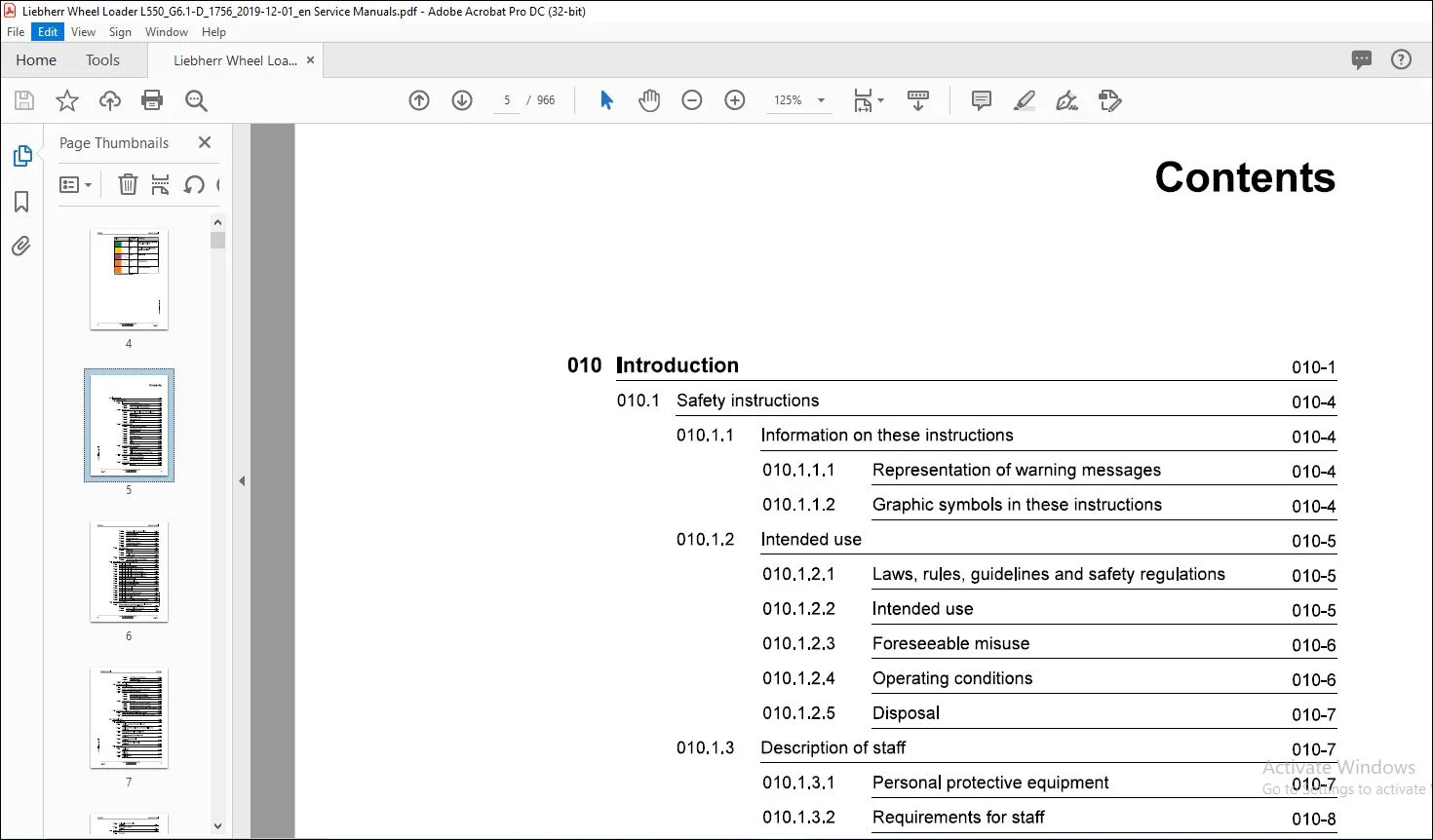
TABLE OF CONTENTS:
Liebherr L 550 1756 Wheel Loader Service Manual – PDF DOWNLOAD
010.1 Safety instructions 010-4
010.1.1 Information on these instructions 010-4
010.1.1.1 Representation of warning messages 010-4
010.1.1.2 Graphic symbols in these instructions 010-4
010.1.2 Intended use 010-5
010.1.2.1 Laws, rules, guidelines and safety regulations 010-5
010.1.2.2 Intended use 010-5
010.1.2.3 Foreseeable misuse 010-6
010.1.2.4 Operating conditions 010-6
010.1.2.5 Disposal 010-7
010.1.3 Description of staff 010-7
010.1.3.1 Personal protective equipment 010-7
010.1.3.2 Requirements for staff 010-8
010.1.3.3 Operating company 010-8
010.1.3.4 Operator 010-9
010.1.3.5 Maintenance staff 010-9
010.1.3.6 Refrigeration technician 010-10
010.1.3.7 Slinger 010-11
010.1.3.8 Spotter 010-12
0101.4 Protective devices on the machine 010-12
010.1.4.1 Operator’s cab 010-12
010.1.4.2 Roll over protective structure (ROPS) 010-13
010.1.4.3 Falling object protective structures (FOPS) 010-13
0101.5 Emergency equipment on the machine 010-13
010.1.5.1 Emergency exit (standard) 010-13
010.1.5.2 Fire extinguisher (option) 010-14
010.1.6 Safe operation 010-14
010.1.6.1 Intoxicants 010-14
010.1.6.3 Transporting machine 010-15
010.1.6.4 Access to machine 010-15
010.1.6.5 Machine danger zone 010-16
010.1.6.6 Visibility 010-16
010.1.6.7 Protection against vibration 010-17
010.1.6.8 Operation of machine 010-18
010.1.7 Safe maintenance 010-21
010.1.7.1 Spare parts 010-21
010.1.7.2 Heavy parts 010-21
010.1.7.3 Regular checks 010-22
010.1.8 Modifications to the machine 010-22
010.1.8.1 Modifications, add-ons and retrofittings 010-22
Special tools for maintenance and repair work 010-23
010.21 Special tools, general 010-23
010.2.2 Special tools for the diesel engine 010-25
010.2.3 Special tools for lift cylinders with Z kinematics 010-29
010.2.4 Special tools for tilt cylinders with Z kinematics 010-29
010.2.5 Special tools for lift cylinders with industrial lift arms 010-30
010.2.6 Special tools for tilt cylinders with industrial lift arms 010-31
010.2.7 Special tools for steering wheel 010-31
010.2.8 Special tools for steering cylinders 010-32
010.2.8 Special tools for the electrical system 010-32
010.2.10 Special tools for the transmission 010-33
010.2.11 Special tools for front axle 010-34
010.2.12 Special tools for rear axle 010-35
010.2.13 Special tools for the air conditioning system 010-35
010.2.14 Special tools for Grammer driver’s seat 010-36
010.2.15 Special tools for cab glazing 010-37
010.2.16 Special tools for the central lubrication system (Liebherr) 010-37
010.3.1.1 Range of application and purpose 010-38
010.3.1.2 Other applicable documents 010-38
010.3.1.4 Tightening torques 010-39
010.3.2 Liebherr standards for assembly instructions and tightening torques010-45
010.4 Preservation guidelines 010-46
0104.1 General information 010-46
010.4.2 Machine out of service for an unknown period of time 010-46
0104.3 Putting the machine out of service 010-47
010.4.3.1 Out of service for up to 2 months 010-47
010.4.3.2 Out of service for up to 12 months 010-48
010.4.3.3 Out of service for longer than 12 months 010-49
0104.4 Putting back into service 010-49
010.4.4.1 After being out of service for 2 months 010-49
010.4.4.2 After being out of service for 12 months 010-50
0104.43 After being out of service for longer than 12 months 010-50
010.5 Preservation guidelines for the SCR system 010-51
010.5.1 Putting out of service for longer than 2 months 010-51
010.5.2 Starting up after being out of service for longer than 2 months 010-51
020 Technical data 020-1
020.1 Overall machine 020-6
020.1.1 Complete machine with bucket (Z lift arms)
L550-1756; 020-6
020.1.2 Complete machine with loading bucket (industrial lift arms)
L550-1756; 020-7
0201.3 Working attachment: light material bucket
L550-1756; 020-9
020.14 Working attachment: high dump bucket
L550-1756; 020-10
0201.5 Working attachment: forklift
L 550-1756; 020-12
020.1.6 Working attachment: log grappler
L550-1756; 020-13
020.2 Drive group 020-15
020.2.1 Diesel engine
L550-1756; 020-15
0202.2 Fuel tank
L550-1756; 020-16
0202.3 Fuel level sensor
L550-1756; 020-16
L550-1756; 020-16
020.2.5 Compressed air system
L 550-1756; 020-17
020.3 Cooling system 020-18
020.3.1 Fan pump
L550-1756; 020-18
020.3.2 Fan motor
L550-1756; 020-18
020.3.3 Hydraulic oil temperature sensor B8
L 550-1756; 020-18
020.4 Working hydraulics 020-19
020.4.1 Working pump
L550-1756; 020-19
020.4.2 Control valve block for Z kinematics
L 550-1756; 020-19
020.4.3 Control valve block for industrial lift arms
L550-1756; 020-20
020.4.4 Pilot control valve block
L550-1756; 020-20
020.4.5 Pilot control hydro accumulator
L 550-1756; 020-20
020.46 Stabilisation module
L 550-1756; 020-21
020.4.7 Ride control hydro accumulator
L550-1756; 020-21
020.4.8 Z kinematics lift cylinder
L 550-1756; 020-21
020.4.9 Z kinematics tilt cylinder
L 550-1756; 020-21
020.4.10 Lift cylinder for industrial lift arms
L 550-1756; 020-22
020.4.11 Tilt cylinder for industrial lift arms
L550-1756; 020-22
020.5 Hydraulic components 020-23
020.5.1 Return filter
L 550-1756; 020-23
020.5.2 Breather filter
L550-1756; 020-23
020.6 Steering system 020-24
020.6.1 Steering pump
L 550-1756; 020-24
0206.2 Servostat
L550-1756; 020-24
L550-1756; 020-24
0206.4 Steering damper hydro accumulator
L550-1756; 020-25
0206.5 Emergency steering pump
L550-1756; 020-25
020.6.6 Emergency steering pressure switch B3
L550-1756; 020-25
0206.7 Emergency steering check pressure switch B3a
L550-1756; 020-25
0206.8 Joystick steering control valve block
L550-1756; 020-26
020.7 Brake system 020-27
020.7.1 Brake pump
L550-1756; 020-27
020.72 Compact brake valve
L550-1756; 020-27
020.7.3 Service brake hydro accumulator
L550-1756; 020-27
020.7.4 Brake light pressure switch B12
L550-1756; 020-27
020.7.5 Brake accumulator pressure sensor B19
L550-1756; 020-28
020.7.6 Parking brake hydro accumulator
L550-1756; 020-28
020.8 Electrical system 020-29
0208.1 Central control unit (Master5-Premium)
L550-1756; 020-29
0208.2 Input module
L550-1756; 020-29
020.8.3 Output module
L550-1756; 020-29
0208.4 Battery
L550-1756; 020-30
020.8.5 Voltage transformer
L550-1756; 020-30
0208.6 Reversing camera
L550-1756; 020-30
020.9 Gearbox 020-31
020.9.1 Transmission
L550-1756; 020-31
020.9.2 Filter bypass switch B85
L550-1756; 020-31
020.9.3 Proportional solenoid for gear shifting Y1, Y2, Y3, Y4, Y5, Y6
L550-1756; 020-31
020.9.4 Pressure sensor B80, B81
L550-1756; 020-32
020.9.5 Speed sensor B82, B83, B84
L550-1756; 020-32
020.9.6 Transmission oil temperature sensor B86
L550-1756; 020-32
020.9.7 Proportional solenoid for position control Y7
L550-1756; 020-33
020.10 Axles and drive shafts 020-34
020.10.1 Front axle
L550-1756; 020-34
020.10.2 Rear axle
L550-1756; 020-34
020.10.3 Cardan shaft between engine and transmission
L 550-1756; 020-34
020.10.4 Cardan shaft between transmission and front axle
L550-1756; 020-35
020.10.5 Drive shaft between transmission and rear axle
L550-1756; 020-35
020.10.6 Tyres
L550-1756; 020-35
020.10.6.2 Tyres for timber work 020-36
020.10.6.3 Special tyres 020-37
020.11 Steel parts of the basic machine 020-38
020.11.1 Ballast weights
L 550-1756; 020-38
020.11.1.1 Standard (Z kinematics) 020-38
020.11.1.2 Foam-filled tyres or tracks 020-38
020.11.1.3 Industrial lift arms and timber grabber 020-38
020.12 Working attachment 020-39
020.12.1 Quick coupler locking hydraulic cylinder
L550-1756; 020-39
020.13 Operator’s cab, heating and air conditioning 020-40
020.13.1.1 Air conditioning compressor 020-40
020.13.2 Air conditioning pressure switch
L550-1756; 020-40
020.14 Lubrication system 020-41
020.14.1 Central lubrication system (Liebherr)
L550-1756; 020-41
020.14.1.1 Central lubrication pump 020-41
020.14.1.2 Progressive distributor 020-41
020.14.2 Progressive distributor
1550-1756; 020-42
020.14.21 MX-F 020-42
020.14.22 MX-F25 020-42
020.14.2.3 MX-F 45 020-43
020.1424 MX-F75 020-43
020.14.25 MX-F105 020-43
020.14.3 Progressive distributor SXE-2
L550-1756; 020-43
020.14.3.1 SXE-2/MX-F 020-43
020.14.3.2 SXE-2100 020-43
020.14.3.3 SXE-2 150 020-44
020.14.34 SXE-2 220 020-44
020.14.3.5 SXE-2 400 020-44
020.14.36 SXE-2760 020-44
030 Maintenance 030-1
030.1 Maintenance and inspection schedule 030-11
030.2 Filling quantities and lubrication chart 030-16
030.2.1 Lubricant filling quantity
L550-1756; 030-16
0302.2 Fuel and operating fluid filling quantity
L550-1756; 030-16
030.3 Lubricants and fuels 030-17
030.3.1 General information on lubricants and fuels 030-17
030.3.1.1 General questions 030-17
030.3.1.2 Safety data sheets 030-17
030.3.1.3 Technical data sheets 030-17
030.3.1.4 Specific Liebherr standards 030-17
030.3.2 General information on changing lubricants and fuels 030-17
030.3.3 Converting hydraulic system from mineral oils to biodegradable
hydraulic fluids 030-18
030.3.4 Diesel fuels
L550-1756; 030-18
030.3.4.1 Minimum quality requirement 030-18
030.34.2 Operating temperatures of diesel fuels 030-19
030.34.3 Minimum quality requirement 030-19
030.3.5.1 Liebherr recommendation 030-19
030.3.5.2 Minimum quality requirement 030-19
Engine oils
030.3.6.1 Liebherr recommendation 030-20
030.3.6.2 Minimum quality requirement 030-20
030.3.6.3 Changing intervals 030-20
030.3.6.4 Complicating factors 030-21
Refrigerant
Coolant
030.3.8.1 Requirements for the water used 030-22
030.3.8.2 Antifreeze and corrosion inhibitor 030-22
030.3.8.3 Minimum quality requirement 030-22
Hydraulic oil
030.3.9.1 Liebherr recommendation 030-22
030.3.9.2 Minimum quality requirement 030-23
030.3.9.3 Oil analysis 030-23
030.3.9.4 Oil change 030-23
Splitter box oil
030.3.10.1 Liebherr recommendation 030-24
030.3.10.2 Minimum quality requirements 030-24
Gear oil
030.3.11.1 Liebherr recommendation 030-24
L550-1756;
030.3.13.1 Liebherr recommendation 030-25
030.3.13.2 Minimum quality requirement 030-25030.3.14 Windscreen washer fluid
L550-1756; 030-26
030.3.14.1 Liebherr recommendation 030-26
030.3.14.2 Minimum quality requirement 030-26
030.3.15 Refrigerant oil for air conditioning compressor
L550-1756; 030-26
030.3.15.1 Liebherr recommendation 030-26
030.4 Maintenance tasks 030-27
0304.1 Safety precautions
L550-1756; 030-27
0304.2 Preparatory tasks for maintenance 030-27
030.421 Maintenance positions
L550-1756; 030-28
030.4.2.2 Opening the service hatches
L550-1756; 030-29
030.423 Turning off the battery main switch
L550-1756; 030-33
030.4.3 Overall machine 030-34
030.4.3.1 Checking machine is in proper condition
L 550-1756; 030-34
030.4.3.2 Removing loose parts, dirt, ice and snow from
machine
L550-1756; 030-36
030.4.3.3 Cleaning machine
L550-1756; 030-36
030.4.3.4 Changing the VCl-capsules
L550-1756; 030-39
030.4.3.5 Qil analyses
L550-1756; 030-42
030.44 Drive group 030-49
030.4.4.1 Checking diesel engine oil level
L 550-1756; 030-49
030.4.4.2 Diesel engine: changing the diesel engine oil
L550-1756; 030-52
030.44.3 Diesel engine: changing oil filter
L550-1756; 030-55
030.4.4.4 Checking diesel engine belt drive
L550-1756; 030-56
030.4.4.5 Changing diesel engine belt drive
L 550-1756; 030-57
030.4.4.6 Checking fastening of diesel engine control units and
sensor cable connections
L550-1756; 030-58
0304.4.8 Diesel engine: changing oil separator filter cartridge
030.4.4.9 Diesel engine: Changing the heating flange
030.4.4.10 Fuel tank: Draining off condensate and sediment
030.4.4.11 Fuel pre-filter: Draining off condensate
030.4.4.12 Changing fuel pre-filter cartridge
030.4.4.13 Changing fuel fine filter element
030.4.4.14 Diesel exhaust fluid tank: checking ventilation
030.4.4.15 Air filter system: Cleaning the service cover and dust
030.4.4.16 Cleaning or changing the main element of the air
030.4.4.17 Air filter system: Changing the safety element
030.4.4.18 Splitter box: Checking the oil level
030.4.4.19 Splitter box: Changing the oil
030.4.4.20 Checking that the diesel engine intake and exhaust
030.4.4.21 Checking the diesel engine for leaks, contamination
0304.4.22 Diesel engine: checking profile clamps
030.4.4.23 Diesel particulate filter: Cleaning filter module
0304.4.24 Changing the compressed air dryer
030.4.4.25 Checking the compressed air system
Cooling system 030-90
0304.51 Cooling system: Checking the coolant level
LBHM2252622/01/211-20191218_140519/en
030.4.5.3 Cleaning the cooling system
030.45.4 Changing coolant in cooling system
Hydraulic components 030-102
030.4.6.1 Hydraulic tank: Checking the oil level
030.4.6.2 Draining off condensate and sediment from the
030.4.6.3 Change the return filter insert in the hydraulic tank.
030.4.6.4 Changing the hydraulic tank breather filter
030.4.6.5 Hydraulic tank: analysing the oil
030.4.6.6 Changing the oil in the hydraulic tank
Steering system 030-112
030.4.7.1 Steering: Checking the function
030.4.7.2 Steering cylinders: Lubricating the bearings
030.4.8.2 Checking service brake discs for wear
030.48.3 Checking the gap and wear on the parking brake
030.48.4 Emergency actuation of parking brake: checking the
030.4.8.5 Checking emergency parking brake actuation
Electrical system 030-124
030.4.9.1 Checking function of the lighting and horn
030.4.9.2 Batteries: Checking the acid level and terminals
0304.93 Control lever: Change the travel direction switch
rocker and cap.
L550-1756; 030-127
030.4.9.4 Personnel detection: cleaning sensor
L550-1756; 030-129
030.4.10 Gearbox 030-130
030.4.10.1 Transmission: checking the oil level
L550-1756; 030-130
0304.10.2 Changing gear oil and gear oil filter
L550-1756; 030-133
0304.10.3 Change the transmission hydrostat oil filter.
L550-1756; 030-136
030.4.11 Axles and drive shafts 030-137
0304.11.1 Axles Changing the oil
L550-1756; 030-137
030.4.11.2 Checking drive shafts
L550-1756; 030-139
030.4.11.3 Checking the tyre pressure
L550-1756; 030-141
030.4.11.4 Checking the wheel tightness
L550-1756; 030-143
030.4.12 Steel parts of the basic machine 030-143
0304.12.11 Lubricating the articulation bearing and the rear axle
oscillating bearing
L550-1756; 030-143
030.4.12.2 Cooler hood: Lubricating moving parts with pene-
trating oil
L550-1756; 030-144
030.4.12.3 Engine hood: Lubricating moving parts with pene-
trating oil
L550-1756; 030-145
0304.124 Right cab access: Lubricating moving parts with
penetrating oil
L550-1756; 030-146
030.4.12.5 Service hatches: Cleaning and maintaining the seals
L550-1756; 030-146
030.4.13 Working attachment 030-147
030.4.13.1 Lubricating the lift arms and working attachment
L550-1756; 030-147
030.4.13.2 Lift arms: Checking the bucket bearing seals
L550-1756; 030-149
030.4.13.3 Checking the lift arm bucket bearing bushings
1550-1756; 030-150
030.4.13.4 Checking the lift arm bucket stops
L550-1756; 030-151
copyright ® Liebher-Werk Bischofshofen GmbH 2019
16 LIEBHERR 1550-1756
Service manual
and replace if necessary
L 550-1756; 030-152
030.4.13.6 Lubricate and test the bearings on the quick coupler.
L550-1756; 030-155
030.4.13.7 High dump bucket: Lubricating the bearing
L550-1756; 030-156
0304.14 Operator’s cab, heating and air conditioning 030-156
030.4.14.1 Operator’s cab: cleaning the fresh and recirculated
air filters
L550-1756; 030-156
030.4.14.2 Changing the fresh and recirculated air filters in the
cab
L 550-1756; 030-158
030.4.14.3 Safety belt: Checking the condition and function
L550-1756; 030-160
030.4.144 Testing the windscreen washer system
L 550-1756; 030-161
030.4.14.5 Windscreen washer system: Topping up windscreen
washer fluid
L550-1756; 030-161
030.4.14.6 Cab: Lubricating the lock and cylinder with pene-
trating oil
L550-1756; 030-162
030.4.14.7 Cab: Cleaning and maintaining the seals
L 550-1756; 030-162
030.4.14.8 Heating and air conditioning: Checking the function
L550-1756; 030-163
030.4.15 Lubrication system 030-165
030.4.15.1 Checking the level in the grease reservoir of the
central lubrication system
L 550-1756; 030-165
030.4.15.2 Central lubrication system: Checking the pipes,
hoses and lubrication points for leaks and damage
L550-1756; 030-166
° 030.4.15.3 Central lubrication system: Checking the lubrication
3: of the bearings
g L550-1756; 030-167
g 030.5 Testing and adjustment checklist
5 L550-1756; 030-168
5 030.6 Testing and adjustment tasks 030-175
8 0306.1 Safety precautions
g L550-1756; 030-175
030.6.2 Overall machine 030-175
030.6.2.1 Preparing for adjustment procedures
L550-1756; 030-175
copyright ® Liebherr-Werk Bischofshofen GmbH 2019
550-1756 LIEBHERR 17
Contents Service manual
030.6.2.2 Hydraulic oil: operating temperature
L550-1756; 030-177
0306.2.3 Gear oil operating temperature
1550-1756; 030-178
030.6.2.4 Service management
L550-1756; 030-178
030.6.3 Drive group 030-179
030.6.3.1 Pedals: calibration
L 550-1756; 030-179
030.6.3.2 Reading the diesel engine service files
L550-1756; 030-181
030.6.4 Cooling system 030-182
030.6.4.1 Fan speed proportional solenoid valve
L550-1756; 030-182
030.6.5 Working hydraulics 030-184
030.6.5.1 Multi-lever control (optional): Calibration
1550-1756; 030-184
030.6.5.2 Calibrating working hydraulics angle sensors
L550-1756; 030-186
030.6.5.3 Proportional solenoids in the control valve block: cali-
bration
1550-1756; 030-189
0306.5.4 Pilot control valve block: pressure reducing valve
L550-1756; 030-193
030.6.5.5 Working pump: flow regulator (standby pressure)
L550-1756; 030-194
030.6.5.6 Working pump flow regulator (differential pressure)
L550-1756; 030-195
030.6.5.7 Working pump: power regulator
1550-1756; 030-197
0306.5.8 Z-bar kinematics control valve block: secondary pres-
sure relief valves
L 550-1756; 030-199
030.6.5.9 Z-bar kinematics control valve block: primary pres-
sure relief valve
L 550-1756; 030-201
030.6.5.10 Z-bar kinematics control valve block: LS-pressure
cut-off
L550-1756; 030-203
030.6.5.11 Industrial lift arms control valve block (option): secon-
dary pressure relief valves
1550-1756; 030-204
030.6.5.12 Industrial lift arms control valve block (option):
primary pressure relief valve
1550-1756; 030-207
copyright ® Liebher-Werk Bischofshofen GmbH 2019
18 LIEBHERR 550-1756
LBHM2252622/01/211-20191218_140519/en
pressure cut-off
030.6.5.14 Stabilisation module cut-out function
030.6.5.15 Ride control hydro accumulator nitrogen filling
Hydraulic components 030-212
nitrogen filling
030.6.6.2 Checking the hydraulic lines for damage
Steering system 030-218
L 550-1756; 030-218
tion (machine with steering wheel steering)
L550-1756; 030-218
tion (machine without steering wheel steering)
030.6.7.4 Control block for joystick steering (option): calibration
030.6.7.5 Steering pump: LS pressure cut-off valve
030.6.7.6 Steering pump flow regulator (standby pressure)
L550-1756; 030-226
L550-1756; 030-227
lation position of position sensors
Brake system 030-229
030.6.8.1 Brake accumulator pressure sensor B19: deviation
030.6.8.2 Compact brake valve hydro accumulator charging
030.6.8.3 Service brake pressure
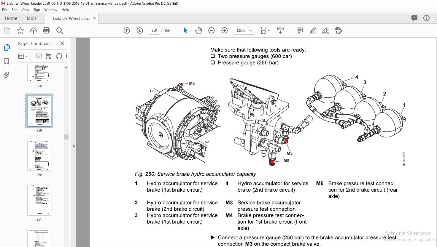
030.6.8.4 Service brake hydro accumulator capacity
Contents
030.6.9.1 Central control unit (Master5): creating service file
030.6.9.2 Central control unit (Master5): software update
030.6.9.3 Central control unit (Master5): resetting to factory
0306.9.4 Central control unit (Master5): connecting Sculi diag-
030.6.9.5 Central control unit (Master5): connecting LiFT func-
030.6.9.6 Addressing CAN module and checking system infor-
Gearbox 030-248
030.6.10.1 Gearbox: basic calibration
030.6.10.2 Gearbox: service calibration
030.6.10.3 Transmission control unit: software update
Axles and drive shafts 030-254
030.6.11.1 Tyres: setting radius
Working attachment 030-255
030.6.12.1 Valve block for quick coupler (option): Pressure
030.6.12.2 Parameters for lift arm geometry
030.6.12.3 Working attachment: automatic return of 3rd function
Operator’s cab, heating and air conditioning 030-258
030.6.13.1 Checking the pressure and temperature conditions of
Options 030-259
030.6.14.1 Skyview 360°: calibration
030.6.14.2 Personnel detection: transmitting configuration files
Service manual Contents
040.1 Engine 040-3
0401.1 Diesel engine overview
L550-1756; 040-3
040.1.2 Electrical components of diesel engine
L550-1756; 040-7
040.1.3 Ambient temperature sensor
L550-1756; 040-10
040.1.5 Fuel system 040-16
040.1.5.2 Fuel level sensor
L550-1756; 040-19
040.1.5.3 Separ fuel pre-filter
L550-1756; 040-21
040.16 Air filter system 040-21
040.1.6.1 Air filter
L550-1756; 040-22
040.1.6.2 Vacuum switch
L550-1756; 040-23
040.1.7 Exhaust system 040-23
040.1.7.1 Exhaust gas treatment (stage V): overview
L 550-1756; 040-24
040.1.7.2 Exhaust gas treatment (stage IV / tier 4f): overview
L550-1756; 040-33
040.1.7.3 Metering unit
L550-1756; 040-38
040.1.7.4 Sampling module
L 550-1756; 040-41
040.1.7.5 Exhaust treatment sensors
L550-1756; 040-42
0401.8 Compressed air system 040-43
040.1.8.1 Overview of the compressed air system
L550-1756; 040-44
$ 040.1.8.2 Compressor
$ 1550-1756; 040-46
py
by 040.1.8.3 Air dryer
g L550-1756; 040-47
& 040.1.8.4 SCR system air supply valve
S L550-1756; 040-48
§ 040.2 Clutch
z L550-1756; 040-49
040.3 Splitter box
L550-1756; 040-51
Contents Service manual
050 Cooling system 050-1
050.1 Cooling system: General overview
L550-1756; 050-2
050.2 Cooling system hydraulics 050-3
050.2.1 Overview of cooling system hydraulics
L550-1756; 050-4
050.2.2 Fan pump
L550-1756; 050-8
050.2.3 Fan motor
L 550-1756; 050-9
050.3 Cooling system electronics 050-13
050.3.1 Overview of electrical controls of cooling system
L550-1756; 050-13
050.3.2 Hydraulic oil temperature sensor
L550-1756; 050-16
050.4 Cooler 050-18
050.4.1 Cooler unit
L 550-1756; 050-18
050.5 Reversible fan drive 050-19
050.5.1 Overview of reversible fan drive
L 550-1756; 050-19
050.5.2 Fan reversal valve block
L 550-1756; 050-21
060 Working hydraulics 060-1
060.1 Overview of Z-bar kinematics working hydraulics
L550-1756; 060-2
060.2 Overview of working hydraulics for industrial lift arms
L550-1756; 060-11
060.3 Working pump
L550-1756; 060-15
0680.4 Control block for Z-bar kinematics
L550-1756; 060-23
060.5 Control valve block for industrial lift arms
L550-1756; 060-31
060.6 Pilot control 060-38
060.6.1 Pilot control valve block
L550-1756; 060-38
060.7 Ride control 060-40
060.7.1 Overview of ride control system
L550-1756; 060-40
060.7.2 Stabilisation module
L 550-1756; 060-43
copyright ® Liebher-Werk Bischofshofen GmbH 2019
22 LIEBHERR 1550-1756
LBHM2252622/01/211-20191218_140519/en
L550-1756; 060-46
060.8 Electronics of the working hydraulics 060-48
060.8.1 Overview of electrical controls the working hydraulics
L550-1756; 060-48
060.8.2 Working hydraulics angle sensors
L550-1756; 060-50
060.9 Pipe break protection 060-53
060.9.1 Pipe break protection: overview
L550-1756; 060-53
060.9.2 Valve block for pipe break protection
L550-1756; 060-56
060.9.3 Ride control release solenoid valve
L550-1756; 060-57
080 Hydraulic components 080-1
080.1 Hydraulic system: overview
L550-1756; 080-2
080.2 Hydraulic tank 080-5
0802.1 Overview of hydraulic tank
L550-1756; 080-5
080.2.2 Steel tank
L550-1756; 080-7
080.2.3 Return filter
L550-1756; 080-9
080.2.4 Leak oil strainer
L550-1756; 080-10
080.2.5 Breather filter
L550-1756; 080-10
090 Steering system 090-1
090.1 Steering system overview
L550-1756; 090-3
090.2 Steering pump
L550-1756; 090-8
090.3 Servostat
L550-1756; 090-14
090.4 Steering cylinder 090-17
0904.1 Steering cylinder
L550-1756; 090-17
0904.2 Steering stabilisation valve block
L550-1756; 090-20
copyright ® Liebherr-Werk Bischofshofen GmbH 2019
L550-1756 LIEBHERR 23
Contents
steering)
L 550-1756; 090-21
090.5 Emergency steering 090-23
090.5.1 Emergency steering overview
L 550-1756; 090-23
090.5.2 Emergency steering pump
L550-1756; 090-25
090.5.3 Emergency steering electronics 090-27
090.5.3.1 Overview of electrical controls of emergency steering
system
L550-1756; 090-27
090.5.3.2 Emergency steering pressure switch
L550-1756; 090-32
090.5.3.3 Emergency steering check pressure switch
L550-1756; 090-33
090.6 Joystick steering 090-35
090.6.1 Joystick steering: overview (combined with steering wheel steering)
L 550-1756; 090-35
090.6.2 Joystick steering: overview (without steering wheel steering)
L 550-1756; 090-39
090.6.3 Joystick steering control block
L 550-1756; 090-42
090.6.4 Joystick steering electrical system 090-48
090.6.4.1 Electronic control unit for joystick steering: overview
L550-1756; 090-48
090.6.4.2 Joystick with position tracking
L550-1756; 090-55
090.7 2in1 steering 090-57
090.7.1 2in1 steering: total overview
L550-1756; 090-57
090.7.2 Servostat for 2in1 steering
L 550-1756; 090-59
100 Brake system 100-1
100.1 Overview of brake system
L550-1756; 100-2
100.2 Service brake and parking brake 100-7
100.2.1 Brake pump
L 550-1756; 100-7
100.2.2 Compact brake valve
L 550-1756; 100-8
100.3 Parking brake 100-16
LBHM2252622/01/211-20191218_140519/en
100.3.1 Parking brake
L550-1756; 100-16
110 Electrical system 110-1
110.1 Overview of electrical system
L550-1756; 110-2
110.2 Lighting
L550-1756; 110-6
110.3 Circuit diagrams
L550-1756; 110-7
110.4 Electronic control unit 110-9
110.4.1 General overview of electronic control system
L550-1756; 110-9
110.4.2 Central control unit (Master5-Premium)
L550-1756; 110-11
110.4.3 Modules 110-14
110.4.3.1 Overview of the input and output modules
L550-1756; 110-14
110.4.3.2 Input modules
L 550-1756; 110-17
110.4.3.3 Output modules
L550-1756; 110-18
110.5 Electrical components of the driver’s cab 110-21
110.5.1 Door contact switch (inductive sensor)
L550-1756; 110-21
110.6 Electrical components in the rear section 110-22
110.6.1 Battery installation
L550-1756; 110-22
110.6.2 Electric battery main switch
L550-1756; 110-24
120 Gearbox 120-1
120.1 Overview of transmission
L550-1756; 120-2
120.2 Transmission hydraulics 120-15
120.2.1 Overview of transmission hydraulics
L550-1756; 120-15
120.2.2 Gear pump
L550-1756; 120-19
120.2.3 Transmission control valve block
L550-1756; 120-20
120.2.4 Hydrostat module
L550-1756; 120-23
copyright ® Liebherr-Werk Bischofshofen GmbH 2019
1550-1756 LIEBHERR 25
Contents
120.3.1 Overview of electrical control system of transmission
L 550-1756; 120-28
120.3.2 Filter bypass switch
L550-1756; 120-29
120.3.3 Gear shifting proportional solenoid
L550-1756; 120-30
120.3.4 Pressure sensor for hydrostat
L550-1756; 120-31
120.3.5 Engine speed sensor
L550-1756; 120-32
120.3.6 Temperature sensor
L550-1756; 120-33
120.3.7 Proportional solenoid for position control
L550-1756; 120-33
130 Axles and drive shafts 130-1
130.1 Axles 130-2
130.1.1 Front axle
L550-1756; 130-2
130.1.2 Rear axle
L550-1756; 130-7
130.2 Cardan shaits 130-9
130.2.1 Drive shaft between diesel engine and transmission
L550-1756; 130-9
130.2.2 Drive shaft between transmission and front axle
L550-1756; 130-10
130.2.3 Drive shaft between transmission and rear axle
L550-1756; 130-11
140 Steel parts of the basic machine 140-1
140.1 Vehicle frame 140-2
140.1.1 Articulation bearing
L550-1756; 140-2
140.1.2 Articulation lock
L550-1756; 140-4
150 Working attachment 150-1
150.1 Lift arms for Z kinematics 150-2
150.1.1 Z kinematics
L550-1756; 150-2
160.2 Industrial lift arms 150-4
LBHM2252622/01/211-20191218_140519/en
150.2.1 Industrial lift arms
L550-1756; 150-4
150.3 Quick coupler 150-6
150.3.1 Quick coupler
L550-1756; 150-6
1560.3.2 Quick coupler hydraulics 150-7
150.3.2.1 Overview of quick coupler hydraulics
L 550-1756; 150-7
150.3.2.2 Valve block for quick coupler
L550-1756; 150-9
160.3.3 Quick coupler electrics 160-11
150.3.3.1 Quick coupler electric control unit
L 550-1756; 150-11
160 Operator’s cab, heating and air conditioning 160-1
160.1 Overview of operator’s cab, heating and air conditioning unit
L550-1756; 160-2
160.2 Display and control elements 160-4
160.2.1 Accelerator pedal
L550-1756; 160-4
160.3 Heating, ventilation, air conditioning 160-6
160.3.1 Heating, ventilation, air conditioning: General overview
L550-1756; 160-6
160.3.2 Heating and air conditioning unit 160-11
160.3.2.1 Heating and air conditioning unit
L 550-1756; 160-12
160.3.2.2 Blower
L550-1756; 160-16
160.3.3 Air conditioning controller
L 550-1756; 160-17
160.4 Air conditioning 160-20
160.4.1 Basic function of the air conditioning unit
L550-1756; 160-20
160.4.2 Air conditioning compressor
L550-1756; 160-21
160.4.3 Condenser
L550-1756; 160-23
160.4.4 Dryer
L550-1756; 160-24
160.4.5 Air conditioning pressure switch
L550-1756; 160-25
copyright ® Liebherr-Werk Bischofshofen GmbH 2019
L560-1756 LIEBHERR 27
Contents
170.1 Liebherr automatic central lubrication system 170-2
170.1.1 Liebherr automatic central lubrication system: overview
L550-1756; 170-2
170.1.2 Liebherr central lubrication pump
L 550-1756; 170-8
170.1.3 Progressive distributor MX-F
L550-1756; 170-12
170.1.4 Progressive distributor SXE-2
L 550-1756; 170-14
190 Options 190-1
190.1 LIiDAT 190-2
190.1.1 Overview of LiDAT
L 550-1756; 190-2
190.1.2 LiDAT on machine
L 550-1756; 190-4
190.1.3 LiDAT module (LiTU3)
L550-1756; 190-6
190.2 Skyview 360° 190-10
190.2.1 Skyview 360°: complete overview
L 550-1756; 190-10
190.2.2 Skyview 360° on machine
L550-1756; 190-14
190.3 Remote control for door lock
L550-1756; 190-15
190.4 Personnel detection
L 550-1756; 190-18
190.5 Entfall des Lenkstockschalters 190-21
190.5.1 Elimination of steering-column switch: overview
L 550-1756; 180-21
190.5.2 Additional controller (HY-TTC-30S)
L550-1756; 190-23
200 Diagnosis 200-1
200.1 Malfunctions 200-2
200.1.1 Warning symbols 200-2
200.1.2 SCR system waming symbols 200-3
200.1.3 Service code indicator in display 200-4
200.2 Troubleshooting 200-6
200.2.1 Replacing fuses 200-6
LBHM2252622/01/211-20191218_140519/en
200.2.1.2 Fuses on fuse board Ada in the left ballast weight 200-9
200.2.1.3 Fuses on fuse board A4b in the operator’s cab 200-11
Contact us: [email protected]
https://vimeo.com/828979976?share=copy
PLEASE NOTE:
- This is not a physical manual but a digital manual – meaning no physical copy will be couriered to you. The manual can be yours in the next 2 mins as once you make the payment, you will be directed to the download page IMMEDIATELY.
- This is the same manual used by the dealers inorder to diagnose your vehicle of its faults.
- Require some other service manual or have any queries: please WRITE to us at [email protected]
S.V