Liebherr LH 40 M Litronic 1202 (USA / CAN) Machine for Industrial Operator’s Manual SN 89596 – PDF DOWNLOAD
Original price was: $89.95.$28.95Current price is: $28.95.
Liebherr LH 40 M Litronic 1202 (USA / CAN) Machine for Industrial Operator’s Manual SN 89596 – PDF DOWNLOAD
Product ID
Manufacturer: Liebherr-Hydraulikbagger GmbH
Type: LH 40 M Litronic
Type no.: 1202 (USA / CAN)
From Serial no.: 89596
Description
Liebherr LH 40 M Litronic 1202 (USA / CAN) Machine for Industrial Operator’s Manual SN 89596 – PDF DOWNLOAD
FILE DETAILS:
Liebherr LH 40 M Litronic 1202 (USA / CAN) Machine for Industrial Operator’s Manual SN 89596 – PDF DOWNLOAD
Language : English
Pages : 356
Downloadable : Yes
File Type : PDF
DESCRIPTION:
Liebherr LH 40 M Litronic 1202 (USA / CAN) Machine for Industrial Operator’s Manual SN 89596 – PDF DOWNLOAD
Product ID
Manufacturer: Liebherr-Hydraulikbagger GmbH
Type: LH 40 M Litronic
Type no.: 1202 (USA / CAN)
From Serial no.: 89596
Preface:
- This operating manual is intended for you as the machine operator or as a member of the maintenance personnel. It contains warnings, important information and tips for working with the machine. It simplifies the process of familiarisation and getting to know the machine, and helps to avoid faults caused by incorrect operation.
- Compliance with the operating manual increases the reliability and service life of the machine.
- The operating manual must be kept with the machine. Make sure that a copy is always kept close to hand at the workplace.
- Read the operating manual before initial commissioning and subsequently at regular intervals. Everyone who carries out work with or on the machine must be familiar with and use this operating manual.
Examples of this work:
– Operation including setup and fitting attachments, elimination of faults, care,
disposal of service products and consumables
– Maintenance including servicing, inspection and repair
– Transporting or loading the machine
- The owner is responsible for supplementing the operating manual with instructions based on existing national regulations on accident prevention and environmental protection. In addition to this operating manual and the regulations on accident prevention applicable in the user’s country and at the place of use, it is also necessary to comply with the recognised technical rules on safety and technically proficient working.
- Some sections of this operating manual do not apply to all machines.
- Some illustrations in this operating manual may show details and implements that are different from your machine.
- In some illustrations, protective devices and covers have been removed to provide a clearer representation.
- Liebherr machines are subject to continuous development and improvement. This may have resulted in modifications to your machine which are possibly not referred to in this operating manual.
- If you require further explanations or information, please contact Liebherr customer service.
TABLE OF CONTENTS:
Liebherr LH 40 M Litronic 1202 (USA / CAN) Machine for Industrial Operator’s Manual SN 89596 – PDF DOWNLOAD
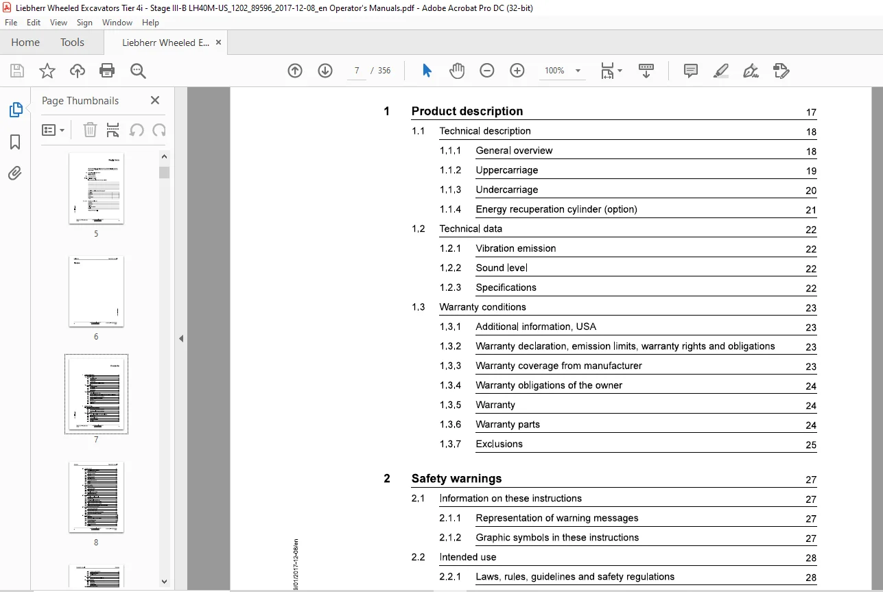
1.1 Technical description 18
1.1.1 General overview 18
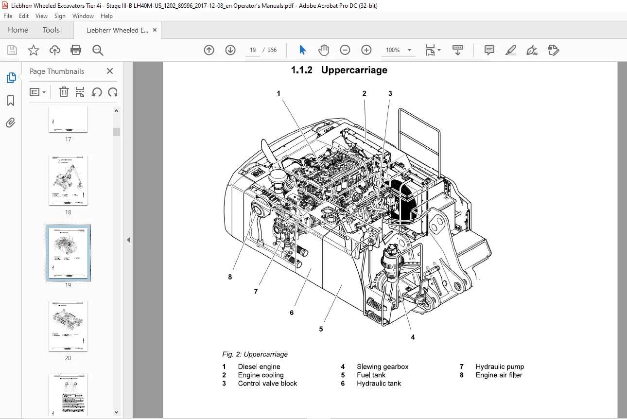
1.1.2 Uppercarriage 19
1.1.3 Undercarriage 20
1.1.4 Energy recuperation cylinder (option) 21
1.2 Technical data 22
1.2.1 Vibration emission 22
1.2.2 Sound level 22
1.2.3 Specifications 22
1.3 Warranty conditions 23
1.3.1 Additional information, USA 23
1.3.2 Warranty declaration, emission limits, warranty rights and obligations 23
1.3.3 Warranty coverage from manufacturer 23
1.3.4 Warranty obligations of the owner 24
1.3.5 Warranty 24
1.3.6 Warranty parts 24
1.3.7 Exclusions 25
2 Safety warnings 27
2.1 Information on these instructions 27
2.1.1 Representation of warning messages 27
2.1.2 Graphic symbols in these instructions 27
2.2 Intended use 28
2.21 Laws, rules, guidelines and safety regulations 28
2.2.2 Intended use 28
2.2.3 Foreseeable misuse 29
2.2.4 Operating conditions 29
225 Disposal 30
2.3.1 Personal protective equipment 31
2.3.2 Requirements for staff 31
2.3.3 Operating company 32
2.3.4 Operator 32
2.3.5 Maintenance staff 33
2.3.6 Electrical engineer 34
2.3.7 Refrigeration technician 34
2.3.8 Rigger 35
2.3.9 Spotter 36
Signs on the machine 37
2.41 Warning signs 37
2.4.2 Safety signs (USA) 46
2.4.3 Information signs 51
2.44 Control description sticker 59
2.4.5 Identification tag (USA) 59
Protective devices on the machine 60
2.5.1 Safety lever or folding console 60
2.5.2 Operator’s cab 60
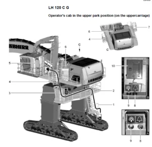
2.5.3 Height-adjustable operator’s cab 60
2.5.4 Tip over protective structure (TOPS) 61
2.5.5 Roll over protective structure (ROPS) 61
2.5.6 Falling object protective structures (FOPS and FGPS) 62
Emergency equipment on the machine 62
2.6.1 Emergency exit (standard) 62
2.6.2 Fire extinguisher (option) 62
2.6.3 Emergency command devices of machine 63
2.6.4 Emergency stop function of machine 63
Safe operation 63
2.7.1 Intoxicants 63
2.7.2 Dangerous fuels and operating fluids 64
2.7.3 Transporting machine 64
2.7.4 Access to machine 65
2.7.5 Machine danger zone 66
2.7.6 Visibility 66
2.7.7 Protection against vibration 67
2.8.1 Machines with height adjustable cab 71
2.9.1 Spare parts 71
2.10.1 Modifications, add-ons and retrofittings 72
3.1 Control and operating elements 75
3.1.1 Overview of operator’s platform 75
3.2.1 Display 79
3.2.10 Radio remote control submenu 102
3.2.12 Display brightness submenu 104
3.2.13 Camera submenu 104
3.2.14 Unit selection submenu 106
3.2.15 System diagnosis submenu 1056
3.2.16 Time zone and time submenu 106
3.2.18 Function settings menu 108
3.2.19 Central lubrication system submenu 110
3.2.20 Maintenance submenu 110
3.2.21 Sensor-controlled low idle automatic submenu (option) M1
3.2.22 Idling time until engine shut-off submenu (option) 11
3.2.23 SF submenu 111
3.2.24 User profile submenu 114
3.2.25 Diesel particulate filter submenu 115
3.2.26 Stick cylinder shut-off submenu (option) 115
3.2.27 Hoist cylinder shut-off submenu (option) 116
3.2.28 Workspace limitation submenu (option) 116
3.2.29 Automatic reversible fan drive submenu (option) 117
3.2.30 Bleeding hydraulic circuit submenu 117
3.2.31 Information menu 118
3.2.32 Operating time submenu 119
3.2.33 Fuel consumption submenu 119
3.2.34 Key assignment submenu 121
3.2.35 Electrical outputs submenu 121
3.2.36 Electrical inputs submenu 121
3.2.37 Tool Control menu 122
3.2.38 Service codes menu 122
3.3 Control 124
3.3.1 Battery main switch 124
3.3.2 Entering and exiting machine 125
3.3.3 Step lighting (option) 126
3.3.4 Emergency exit 126
3.3.5 Fire extinguisher (option) 127
3.3.6 Folding console 127
3.3.7 Operator’s seat 129
3.3.8 Safety belt 134
3.3.9 Exit protection (option) 135
3.3.10 Steering wheel 136
3.3.11 Ignition key 137
3.3.12 Confirmation button 137
3.3.14 Raising and lowering operator’s cab (option) 139
3.3.15 Windscreen 141
3.3.16 Sun blind 143
3.3.17 Viewing devices 144
3.3.18 Lighting 146
3.3.19 Cab lighting system 147
3.3.20 Beacon (option) 148
3.3.21 Windscreen wipers 149
3.3.22 Windscreen washer system 149
3.3.23 Auxiliary heater (option) 150
3.3.24 LiDAT (option) 150
3.4 Operation 151
3.4.1 Inspection tour before putting into service 161
3.4.2 Refuelling 152
3.43 Refuelling with electric refuelling pump (option) 153
3.4.4 Preheating system (option) 154
3.45 Immobiliser (option) 156
3.4.6 Preparing machine for dust intensive application 157
3.4.7 Preparing machine for use in biologically sensitive areas 158
3.4.8 Starting diesel engine 158
3.49 Bringing machine to operating temperature 159
3.4.10 Engine speed and operating mode 169
3.4.11 After starting 161
3.4.12 Sensor-controlled low idle automatic 162
3.4.13 Automatic engine shut-off after idling (option) 162
3.4.14 Shutting off diesel engine 163
3.4.15 Travelling and braking 163
3.4.16 Joystick steering 167
3.4.17 Four wheel steering (option) 168
3.4.18 Travel alarm (option) 169
3.4.19 Selecting operating mode of oscillating axle 170
3.4.20 Supporting machine 172
3.4.21 Controlling working attachment 175
3.4.22 Turning and braking uppercarriage 176
3.4.23 Slewing brake 176
3.4.24 Positioning slewing brake 177
3.4.25 Overload warning system (option) 177
3.4.26 Lowering boom actively (option) 179
3.4.27 Lowering stick actively (option) 179
3.4.28 Selecting the working tool 180
3.4.29 Controlling special working attachment with mini-joystick 180
3.4.30 Changing over control of right mini-joystick (option) 181
3.4.31 Grapple priority (option) 183
3.4.32 AutolLift (Option) 184
3.4.33 Magnet system (option) 184
3.4.34 Reversible fan drive for radiator cleaning (option) 186
3.5.1 Stick cylinder shut-off (option) 188
3.6.1 Working without damaging the machine 202
3.7.1 Using quick coupler 213
3.9 Transport 218
3.9.1 Preparatory activities 218
3.10.1 Jump starting 221
3.10.2 Lowering working attachment when engine is shut off 222
Access points for maintenance work 275
5.4.1 Access points on uppercarriage 275
Preparing for maintenance 277
5.5.1 Preparing for maintenance 277
General maintenance 279
5.6.1 Welding 279
5.6.3 Corrosion-proofing piston rods 279
5.6.4 Cleaning the machine 280
5.6.5 Cleaning the fan and radiator 282
Complete machine 283
5.7.1 Checking machine for proper condition and tightness 283
5.7.2 Checking components for cracks 283
5.7.3 Lubricating hinges, locks and gas pressure springs of doors, hoods and
5.7.4 Cleaning and treating rubber seals on doors and hoods 283
Drive group 284
5.8.1 Diesel engine: Bringing into maintenance position 284
5.8.2 Diesel engine: Checking oil level 284
5.8.3 Diesel engine: Checking condition, tightness and cleanliness 285
5.8.4 Fuel pre-filter: Draining water 286
5.8.5 Air filter: Emptying dust collecting tank 287
5.8.6 Air filter: Replacing main filter cartridge 288
5.8.7 Air filter: Replacing safety filter cartridge 290
5.8.8 Air filter and air lines: Checking tightness and condition 291
5.8.9 Diesel particulate filter (option): Activating and deactivating
Cooling system 299
5.9.1 Checking coolant level 299
5.9.2 Checking cooling system and heat exchanger for contamination and
Working hydraulics 302
5.10.1 Depressurising hydraulic system 302
5.10.2 Hydraulic tank: Checking oil level 302
5.10.3 Hydraulic tank: Draining water and sediments 305
5.10.4 Return filter: Checking and cleaning magnetic rod 306
5.11.1 General information 309
5.12.1 Lubricating axles 310
5.12.2 Checking tyre pressure 31
5.12.3 Tyres: checking foam-filled tyres 312
5.12.4 Wheels: Checking mounting of wheel nuts 313
5.13.1 Lubricating working tool 314
5.13.2 Checking pin connections for secure seating 314
5.13.3 Checking steel parts for cracks 314
5.13.4 Pin bearing: checking for wear 315
5.13.5 Energy recuperation cylinder: Performing visual inspection 315
5.14.1 Filling with windscreen washer fluid 316
5.14.2 Heating: Checking function 316
5.14.3 Auxiliary heater (option): Checking function 318
5.14.4 Switching on air conditioning unit 318
5.14.5 Checking and cleaning condenser 318
5.15.1 Lubrication system: Filling with grease 320
5.15.2 Checking lubrication of bearings (grease collar) 321
5.15.3 Pipes, hoses and lubricating points: Checking tightness and condition 322
5.15.4 Checking function of entire system, pumps and control 322
5.16.1 Slewing gearbox: Checking oil level 328
Index 333
IMAGES PREVIEW OF THE MANUAL:
Contact us: [email protected]
PLEASE NOTE:
- This is the SAME exact manual used by your dealers to fix your vehicle.
- The same can be yours in the next 2-3 mins as you will be directed to the download page immediately after paying for the manual.
- Any queries / doubts regarding your purchase, please feel free to contact [email protected]
S.V