Trusted Business
Verified & Licensed
Virus Free Files
100% Safe Downloads
Secure Payment
SSL Protected
Instant Delivery
Available Immediately
Sale!


Liebherr LR4 624 634 Crawler Loader Series 4 Service Manual – PDF DOWNLOAD
Original price was: $86.95.$36.95Current price is: $36.95.
Liebherr LR4 624 634 Crawler Loader Series 4 Service Manual – PDF DOWNLOAD
Instant PDF Download
Available immediately
Save to Your Device
Download & keep forever
Antivirus Scanned
100% virus-free
Trusted Worldwide
175,000+ customers
Description
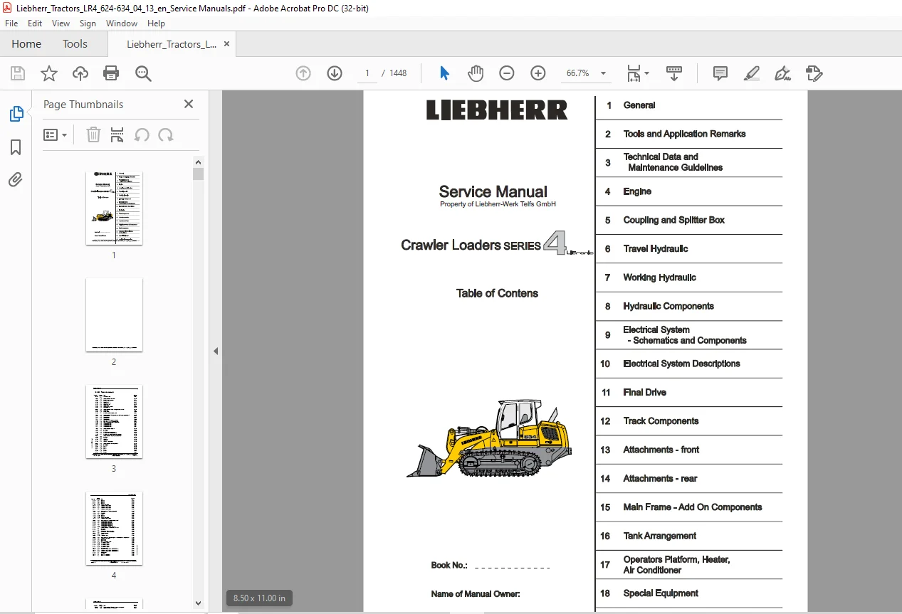
Liebherr LR4 624 634 Crawler Loader Series 4 Service Manual – PDF DOWNLOAD
FILE DETAILS:
Liebherr LR4 624 634 Crawler Loader Series 4 Service Manual – PDF DOWNLOAD
Language : English
Pages : 1448
Downloadable : Yes
File Type : PDF
Size: 204 MB
DESCRIPTION:
Liebherr LR4 624 634 Crawler Loader Series 4 Service Manual – PDF DOWNLOAD
Foreword and explanation:
For information:
- This manual contains technical data, descriptions of design and function, repair and adjustment
instructions as well as numerous drawings, functional views and illustrations of - This manual should simplify competent customer service of our product, however, it does not
replace expert and qualified training and attendance at our factory training classes. - Information which is in the trade considered to be basic knowledge is not included. Operation
and spare parts information can be found in separate documentation. - The manual will be updated and expanded as necessary, when changes occur in series.
- During all activities on the machine, accident prevention regulations and safety guidelines must
be strictly observed. - The manual is intended for the exclusive use of the registered owners and may not be
reproduced complete or in part or passed on to a third person without our written permission
and remains property of LIEBHERR-Werk Telfs GmbH. - We reserve the right to make changes of technical details on the machine in comparison to the
information and drawings in this manual.
Safety guidelines
Introduction
Prior to and during the performance of tests, adjustments and repairs, the following
safety guidelines must be followed:
- Any type of work may only be performed by qualified trained personnel or under the
supervision and responsibility of such personnel. - Qualified trained personnel are persons, who — based on specialized training and experience —
have sufficient knowledge in the general area of earthmoving machinery and the specific
technology of our machines. They must also have knowledge of all applicable laws and general
work protection regulations, guidelines and generally approved rules concerning technology and
be able to evaluate if earthmoving equipment is safe to operate and if the necessary work can be
performed without endangering themselves or third persons. - Never operate a machine with a raised cab/ operator’s platform! The machine may only be
operated with a lowered and secured cab / operator’s platform! - Always adhere to the adjustment values noted in LIEBHERR documentation when performing
adjustment work. - When delivering the machine, the operating personnel must be trained using the currently valid
operating manual. The safety guidelines in that manual must be particularly observed. - These safety guidelines must also be observed when performing testing, adjustment or repair
work. However, there are special repair and/ or inspection tasks, which require different
procedures than specified in the safety guidelines. In such cases, qualified personnel or
individuals performing the work under the supervision of such personnel should assure that
additional safety precautions necessary to insure the safety of those involved in the repair and/
or third parties are taken. The decision to carry out this measures can only be made by qualified
expert personnel.
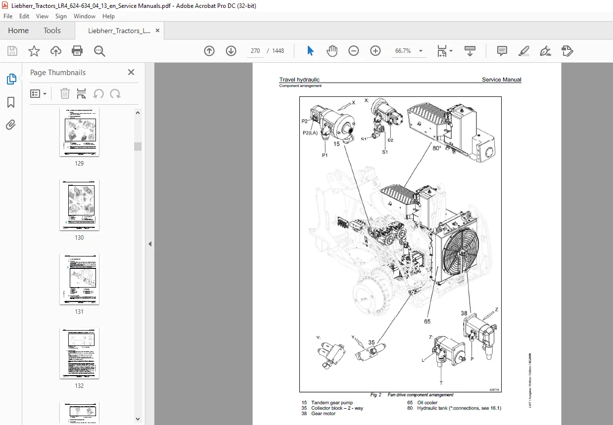
IMAGES PREVIEW OF THE MANUAL:
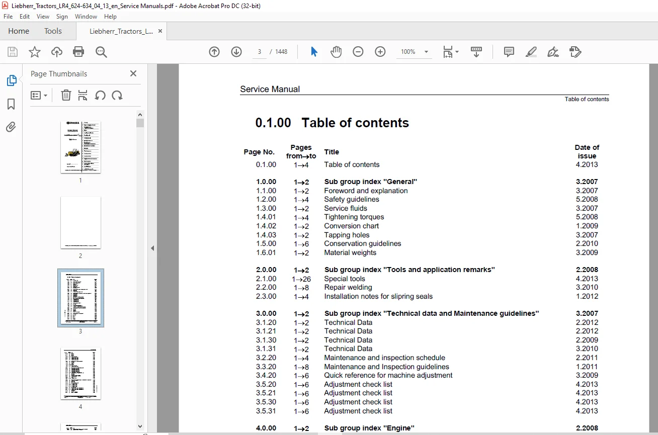
TABLE OF CONTENTS:
Liebherr LR4 624 634 Crawler Loader Series 4 Service Manual – PDF DOWNLOAD
Sub group index “General”
Foreword and explanation
Safety guidelines
Foreword and explanation
Safety guidelines
Service fluids
Tightening torques
Conversion chart
Conversion chart
Tapping holes
Conservation guidelines
Material weights
Material weights
Sub group index “Tools and application remarks”
Special tools
Special tools
Repair welding
Installation notes for slipring seals
Sub group index “Technical data and Maintenance guidelines”
Technical Data
Technical Data
Technical Data
Technical Data
Technical Data
Maintenance and inspection schedule
Maintenance and Inspection guidelines
Quick reference for machine adjustment
Adjustment check list
Maintenance and Inspection guidelines
Quick reference for machine adjustment
Adjustment check list
Adjustment check list
Adjustment check list
Adjustment check list
Sub group index “Engine”
Data page
Data page
Fan and cylinder arrangement
Installation kit- Diesel particle filter
Installation and test list for Diesel particle filter
Sub group index “Coupling and splitterbox™
Data page
Data page
Coupling
Splitterbox
Splitterbox
Coupling — pump output
6.3.30 1-58 Function 3.2012
6.3.31 1-8 Function 3.2012
6.3.32 158 Function 3.2012
6.3.33 158 Function 3.2012
6.4.00 1310 Test and adjustment 4.2013
6.5.20 152 Component arrangement 2.2008
6.5.21 152 Component arrangement 2.2008
6.5.30 152 Component arrangement 2.2008
6.5.31 152 Component arrangement 3.2008
7.0.00 152 Sub group index “Working hydraulic” 3.2007
7.1.20 152 Data page 1.2009
7.1.30 152 Data page 1.2009
7.2.20 1-6 Design 2.2008
7.3.20 1310 Function 1.2008
7.3.30 1310 Function 1.2008
7.4.00 1310 Test and adjustment 2.2013
7.5.20 152 Component arrangement 1.2009
8.0.00 152 Sub group index “Hydraulic components” 2.2009
8.1.20 1-56 Variable displacement pump 3.2007
8.1.30 1-56 Variable displacement pump 6.2006
8.2.20 1-56 Variable displacement motor 3.2007
8.2.30 1-56 Variable displacement motor 2.2008
8.2.31 1-56 Variable displacement motor 2.2008
8.3.20 1510 Regulator pump — Working hydraulic 2.2008
8.4.20 154 Double gear pump — Replenishing / Fan drive 4.2008
8.4.25 1-54 Fan motor 1.2011
8.4.35 1-54 Fan motor 4.2008
8.5.20 1-58 Pilot control — Working hydraulic 3.2009
8.5.25 156 Pilot control — Auxiliary equipment 1.2009
8.6.20 1-56 Control valve block 1.2011
8.7.00 112 Valves 2.2009
8.8.00 1-510 Hydraulic cylinder 4.2011
9.0.00 152 Sub group index “Electrical system — Schematics and components” 3.2009
9.1.30 1-56 Component description 2.2010
9.2.30 152 Function list 1.2010
9.2.31 152 Function list 1.2010
9.3.30 12 Fuses, cross points, notes 1.2008
9.4.20 1576 Current flow diagram 3.2009
9.4.21 1-580 Current flow diagram 3.2012
9.4.30 1-516 Current flow diagram 1.2008
9.4.31 1316 Current flow diagram 1.2008
9.4.32 1576 Current flow diagram 1.2008
9.5.20 12 Instrument panel 1.2010
9.6.20 1-518 Component arrangement — Electrical system 2.2012
9.6.30 1-514 Component arrangement — Electrical system 2.2012
9.6.31 1518 Component arrangement — Electrical system 2.2012
9.7.20 154 Travel joystick 2.2010
9.7.25 1>4 V- joystick 2.2010
9.8.20 1-54 Speed reduction pedal 1.2011
9.8.21 1-54 Speed reduction pedal 1.2011
Sub group index “Electrical system descriptions”
Application Software — travel drive
Application Software — travel drive
Application Software — travel drive
Software PDL — Diesel particle filter
Service Code List
Service Code List
Sub group index “Final drive”
Data page
Data page
Data page
Design and function
Design and function
Sectional view
Sectional view
Sub group index “Track components”
Data page
Data page
Design, function, wear and evaluation
Inspection checklist
Inspection checklist
Wear chart
Track roller frame and idler unit
Track roller
Carrier roller
Tension unit
Sub group index “Attachments – front”
4 in 1 Bucket
Bucket arm
4 in 1 Bucket
Bucket arm
Sub group index “Attachments – rear”
Ripper
Ripper
Ripper
Ripper
Sub group index ” Main frame — Add on components “
Cooler arrangement
Cooler arrangement
Hoist and tilt cylinder mount
Equalizer bar
Equalizer bar
Equalizer bar
Engine mount
Sub group index “Tank arrangement”
Hydraulic tank
Hydraulic tank
Hydraulic tank
Fuel tank
Fuel tank
Battery compartment
Sub group index “Operators platform, heater, air conditioner”
Operators platform
Heater and Blower
Air conditioning system
Operator’s seat — air cushioned
Engine RPM adjustment
18.0.00 152 Sub group index “Special equipment” 5.2008
18.2.20 1-4 Refueling pump 1.2008
18.3.20 1-6 Reversible fan 2.2010
18.3.30 1-6 Reversible fan 3.2008
18.3.31 1-56 Reversible fan 2.2010
18.4.00 1-56 Rope winch 1.2009
19.0.00 152 Sub group index “Additional documentation” 3.2009
6.3.20 152 Schematics Travel Hydraulic 1.2009
6.3.21 152 Schematics Travel Hydraulic 1.2009
6.3.30 152 Schematics Travel Hydraulic 1.2009
6.3.31 152 Schematics Travel Hydraulic 1.2009
6.3.32 152 Schematics Travel Hydraulic 1.2009
6.3.33 152 Schematics Travel Hydraulic 1.2009
7.3.20 11 Schematic Working Hydraulic 1.2008
7.3.30 11 Schematic Working Hydraulic 1.2008
9.4.20 1576 Current Flow Diagram 3.2009
9.4.21 1-580 Current Flow Diagram 3.2012
9.4.30 1516 Current Flow Diagram 2.2007
13,16 3.2007
6 1.2008
9.4.31 1516 Current Flow Diagram 1.2008
9.4.32 1576 Current Flow Diagram 2.2009
Questions? Email us: [email protected]
PLEASE NOTE:
- This is the same manual used by the dealers to diagnose and troubleshoot your vehicle
- You will be directed to the download page as soon as the purchase is completed. The whole payment and downloading process will take anywhere between 2-5 minutes
- Need any other service / repair / parts manual, please feel free to contact [email protected] . We still have 50,000 manuals unlisted
S.V