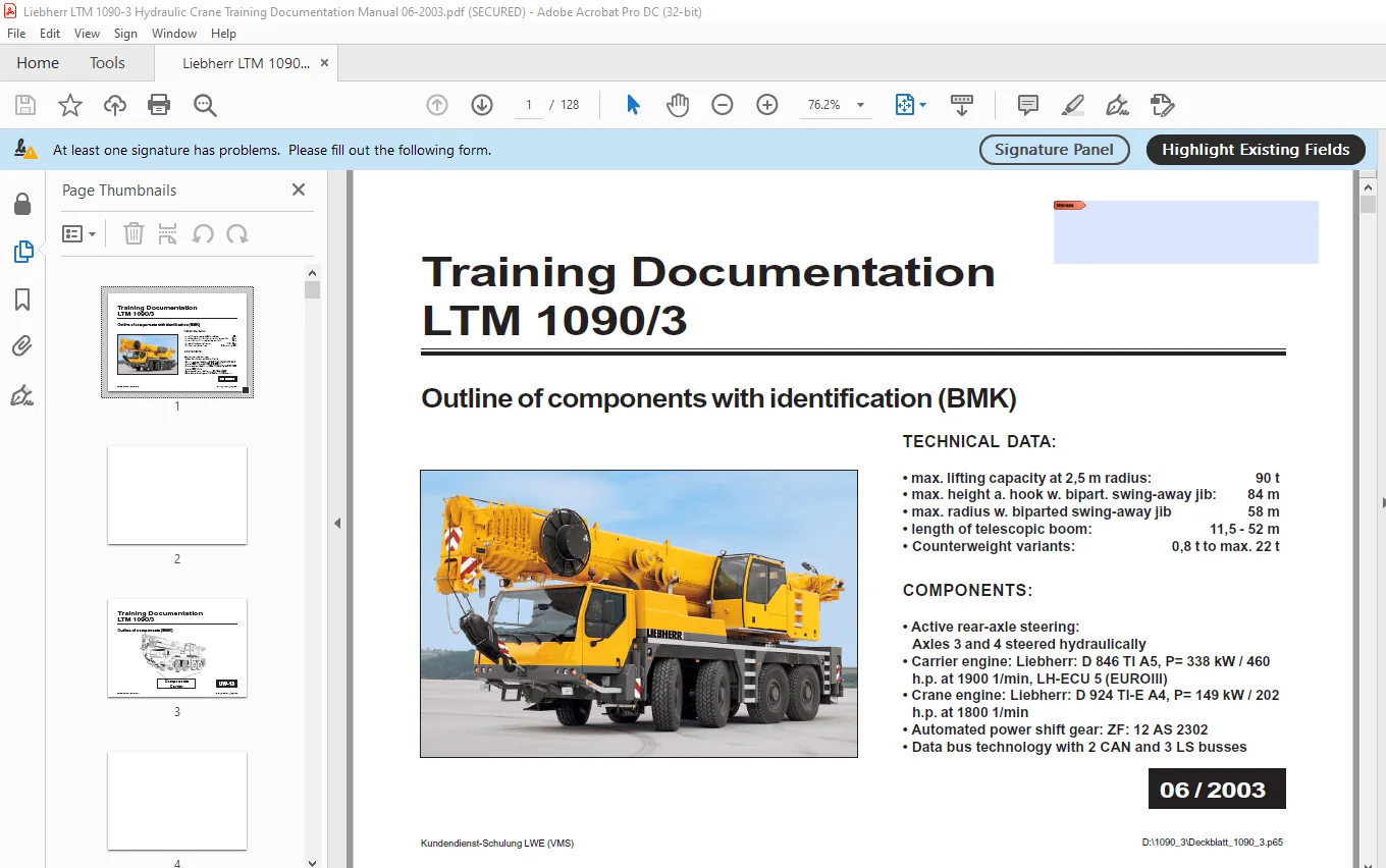
Liebherr LTM 1090-3 Mobile Crane Training Documentation Manual – PDF DOWNLOAD
Original price was: $78.95.$25.95Current price is: $25.95.
Liebherr LTM 1090-3 Mobile Crane Training Documentation Manual – PDF DOWNLOAD
Description
Liebherr LTM 1090-3 Mobile Crane Training Documentation Manual – PDF DOWNLOAD
FILE DETAILS:
Liebherr LTM 1090-3 Mobile Crane Training Documentation Manual – PDF DOWNLOAD
Language : English
Pages : 128
Downloadable : Yes
File Type : PDF
Size: 65.8 MB
TABLE OF CONTENTS:
Liebherr LTM 1090-3 Mobile Crane Training Documentation Manual – PDF DOWNLOAD
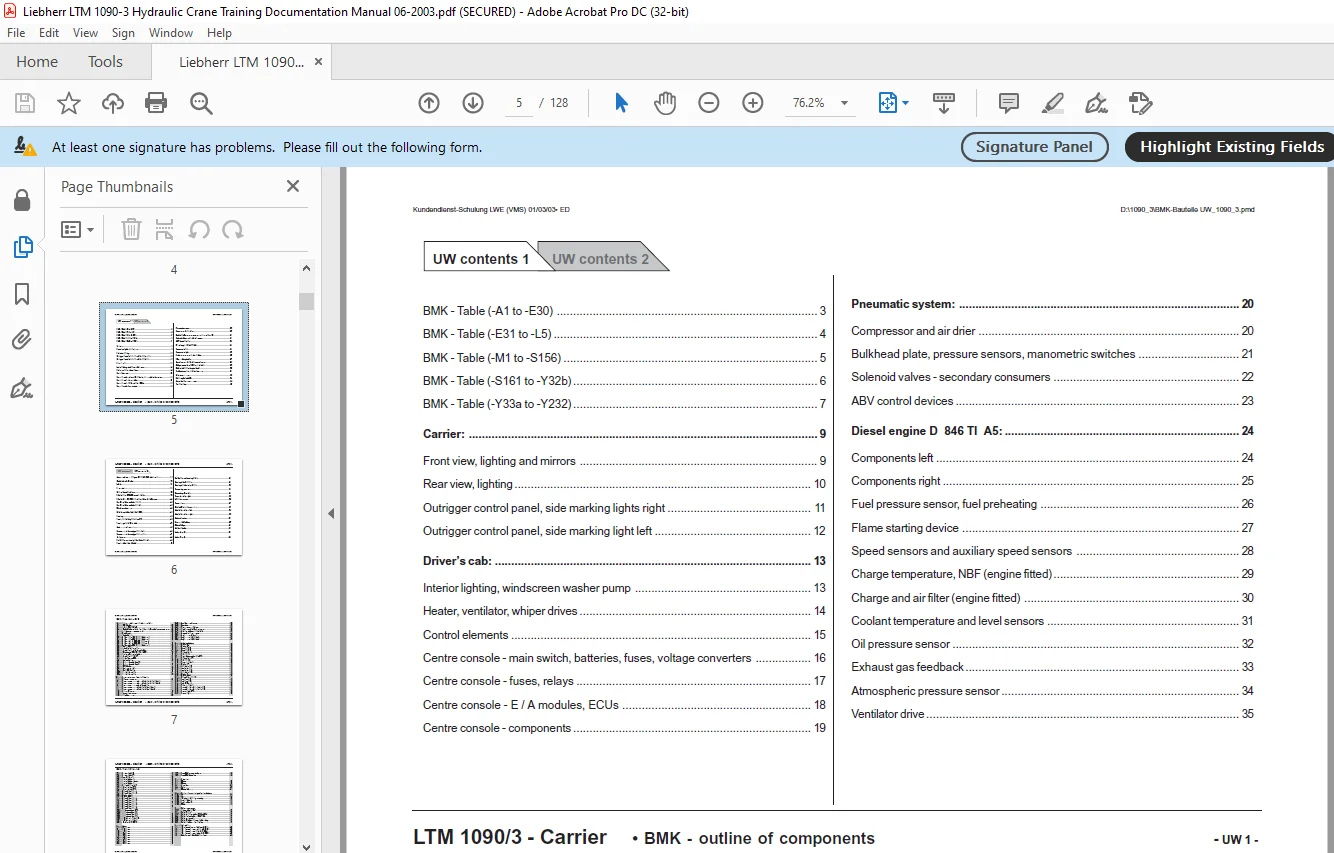
Contents Carrier 5
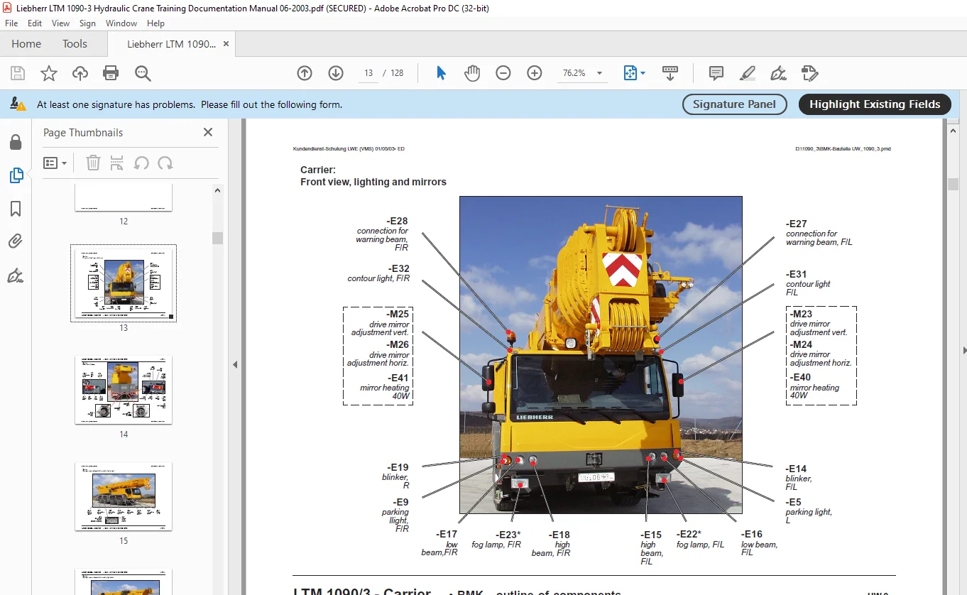
Carrier: 13
Front view, lighting and mirrors 13
Rear view, lighting 14
Outrigger control panel, side marking lights right 15
Outrigger control panel, side marking light left 16
Driver’s cab: 17
Interior lighting, windscreen washer pump 17
Heater, ventilator, whiper drives 18
Control elements 19
Centre console – main switch, batteries, fuses, voltage converters 20
Centre console – fuses, relays 21
Centre console – E / A modules, ECUs 22
Centre console – components 23
Pneumatic system: 24
Compressor and air drier 24
Bulkhead plate, pressure sensors, manometric switches 25
Solenoid valves – secondary consumers 26
ABV control devices 27
Diesel engine D 846 TI A5: 28
Components left 28
Components right 29
Fuel pressure sensor, fuel preheating 30
Flame starting device 31
Speed sensors and auxiliary speed sensors 32
Charge temperature, NBF (engine fitted) 33
Charge and air filter (engine fitted) 34
Coolant temperature and level sensors 35
Oil pressure sensor 36
Exhaust gas feedback 37
Atmospheric pressure sensor 38
Ventilator drive 39
Automated power shift gear ZF 12 AS 2302 with intarder: 40
Clutch and gear actuators 40
Intarder 41
Power train: 42
Outline, control conditions 42
Transfer case VG 2600 – speed selection 43
Transfer case VG 2600 – contact switches and tachy sensor 44
Contact switches on axles 1 and 2 45
Contact switches on axles 3 and 4 45
Wheel speed sensors 46
Eddy current brake Telma Focal 250 47
Steering: 48
Steering and parking brake from OW 48
Steering gear and lack switch 49
Active rear-axle steering: 50
Components in the outrigger casing left 50
Components in the outrigger casing right 51
Angle sensors 52
Hydraulic pump, steering circuit axles 3 and 4 53
Steering plate axles 3 and 4 54
Hydraulic pump centering circuit 55
Steering plate circulation 56
Steering plate centering circuit 57
Supporting system: 58
Supporting valves left 58
Supporting valves right 59
Inclination sensors 60
Suspension: 61
Check-back signal suspension 61
Axle locking valves – left 62
Axle locking valves – right 63
Optional equipment: 64
Emergency actuation 64
Battery charger 65
Additional heater 66
Index -A to -P 67
Contents Superstructure 71
Instruments cabin: 79
Liccon monitor, pedal 79
Master switch left 80
Master switch right 81
Upper console 82
Crane cab: 83
Wiper, radio system 83
Heater, additional heater 84
Additional heater 85
Control cabinet: 86
Swing frame – fuses 86
Swing frame – relays 87
Swing frame – relays 88
Control ON, voltage converter 89
Participants on CAN and LSB 90
EMERGENCY MODE without LICCON system – X-emergency connector 91
EMERGENCY MODE without LICCON system – actuation 92
EMERGENCY MODE without LICCON system – resistances 93
Electric equipment superstructure: 94
Battery box 94
Diesel engine D 924 TI – E 149 KW: 95
Components 95
Sensors 96
Temperature, pressure, speed sensors 97
Cooling system 98
Cooling system 99
Hydraulic equipment superstructure: 100
Outline hydraulic pumps 100
Main control block 101
Main control block with hoist gear 2 102
Main control block – pressure steps 103
Main control block – pressure steps 104
Temperature sensor hydraulic oil 105
Winch 1 106
Winch 2 107
Secondary consumers 108
Slewing gear – control, slewing angle indictor 109
Slewing gear – brake 110
Luffing gear 111
Boom direction 112
Ballasting 113
Pneumatic system – superstructure: 114
Interlock superstructure, platform cabin 114
Superstructure in general: 115
Central lubrification system 115
Cooler hydraulic oil, fuel level sensor 116
Lighting superstructure 117
Telescopic boom: 118
Cable drums, angle and length sensors 118
Boom head 119
Interlocking tele 120
Interlocking gripper 121
Hydraulic swing-away jib: 122
Control 122
Limit switch left 123
Angle sensor and limit switch right 124
Hydraulic components 125
Index -A to -R 127
Need help? Contact: [email protected]
https://vimeo.com/830812241?share=copy
IMAGES PREVIEW OF THE MANUAL:
PLEASE NOTE:
- This is the SAME exact manual used by your dealers to fix your vehicle.
- The same can be yours in the next 2-3 mins as you will be directed to the download page immediately after paying for the manual.
- Any queries / doubts regarding your purchase, please feel free to contact [email protected]
S.V