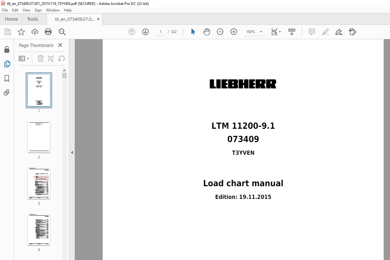
LIEBHERR LTM 11200-9.1 Load chart Manual 073409 T3YVEN – PDF DOWNLOAD
$27.95
LIEBHERR LTM 11200-9.1 Load chart Manual 073409 T3YVEN – PDF DOWNLOAD
Description
LIEBHERR LTM 11200-9.1 Load chart Manual 073409 T3YVEN – PDF DOWNLOAD
FILE DETAILS:
LIEBHERR LTM 11200-9.1 Load chart Manual 073409 T3YVEN – PDF DOWNLOAD
Language : English
Pages : 322
Downloadable : Yes
File Type : PDF
DESCRIPTION:
LIEBHERR LTM 11200-9.1 Load chart Manual 073409 T3YVEN – PDF DOWNLOAD
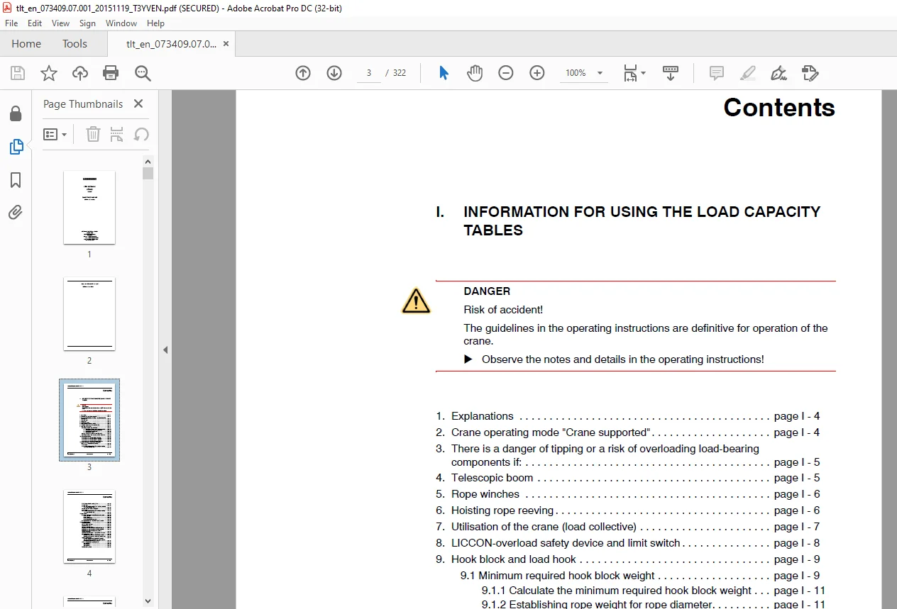
1. Explanations
1.1 The load capacity values in the tables are stated in metric tons [t].
1.2 The working radius is the horizontal gravity center distance of the load from
the rotational axis of the crane superstructure measured at the ground. The
radius stated is valid under load conditions, i.e. including boom flexure.
1.3 Boom positions differing from those given in the load capacity tables are not
permissible.
1.4 The boom may only be manoeuvred into those areas specified in the load
chart, even if no load is suspended, otherwise there is a risk of the crane
toppling.
1.5 The stated load capacities contain the weights of the load bearing, lifting and
slinging tackle. The possible weight for the load to be lifted is therefore
reduced according to the weights of the afore-mentioned tackle.
1.6 Additional information and limitations are specified in the operating mode
symbol for select operating modes. See „Limitation descriptions for operating
modes“ on page 86.
TABLE OF CONTENTS:
LIEBHERR LTM 11200-9.1 Load chart Manual 073409 T3YVEN – PDF DOWNLOAD
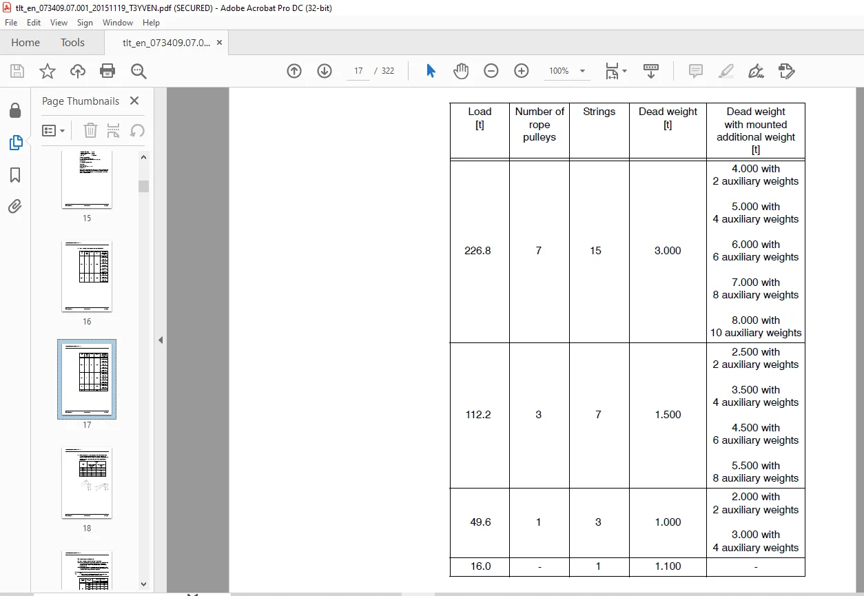
I. INFORMATION FOR USING THE LOAD CAPACITY TABLES...................................................................................................................  3
II. LOAD CAPACITY TABLES............................................................................................................................................  5
1. Explanations.....................................................................................................................................................  6
2. Crane operating mode "Crane supported"...........................................................................................................................  6
3. There is a danger of tipping or a risk of overloading load-bearing components if:................................................................................  7
4. Telescopic boom..................................................................................................................................................  7
5. Rope winches.....................................................................................................................................................  8
6. Hoisting rope reeving............................................................................................................................................  8
7. Utilisation of the crane (load collective).......................................................................................................................  9
8. LICCON-overload safety device and limit switch................................................................................................................... 10
9. Hook block and load hook......................................................................................................................................... 11
	9.1 Minimum required hook block weight.......................................................................................................................... 11
		9.1.1 Calculate the minimum required hook block weight...................................................................................................... 13
		9.1.2 Establishing rope weight for rope diameter............................................................................................................ 13
		9.1.3 Establishing the reeving factor....................................................................................................................... 14
		9.1.4 Calculation examples.................................................................................................................................. 15
	9.2 Load capacity, rope pulleys and operating weight............................................................................................................ 16
	9.3 Distance between hook and pulley set in the boom head....................................................................................................... 18
10. Load capacity reductions........................................................................................................................................ 19
	10.1 Load capacity reduction during T - operation............................................................................................................... 19
	10.2 Load capacity reduction during TN - operation.............................................................................................................. 24
	10.3 Load capacity reduction during TF - operation.............................................................................................................. 37
	10.4 Load capacity reduction with mounted boom nose............................................................................................................. 61
11. Maximum permissible slewing speed of the crane's superstructure with suspended nominal load..................................................................... 62
	11.1 T3-boom.................................................................................................................................................... 62
	11.2 T3-boom with fixed lattice fly jib (F) or with hydraulically adjustable lattice fly jib (NZF).............................................................. 63
	11.3 T3-boom with luffing lattice fly jib (N)................................................................................................................... 64
	11.4 T37-boom................................................................................................................................................... 65
	11.5 T37-boom with fixed lattice fly jib (F) or with hydraulically adjustable lattice fly jib (NZF)............................................................. 66
	11.6 T37-boom with luffing lattice fly jib (N).................................................................................................................. 67
	11.7 T7-boom.................................................................................................................................................... 68
	11.8 T7-boom with fixed lattice fly jib (F) or with hydraulically adjustable lattice fly jib (NZF).............................................................. 69
12. Boom system..................................................................................................................................................... 70
	12.1 Abbreviations for the assemblies of the boom system........................................................................................................ 70
		12.1.1 Main boom............................................................................................................................................ 70
		12.1.2 Y-Guying............................................................................................................................................. 70
		12.1.3 Additional boom...................................................................................................................................... 70
		12.1.4 Telescopic boom extension............................................................................................................................ 70
	12.2 Combination of the assemblies to operating modes........................................................................................................... 71
13. Explanation of symbols.......................................................................................................................................... 72
	Hoisting rope reeving........................................................................................................................................... 72
	Load capacity in metric tons.................................................................................................................................... 72
	Operating mode symbol........................................................................................................................................... 72
	Main boom operating modes....................................................................................................................................... 73
	Additional boom operating modes with fixed lattice fly jib...................................................................................................... 76
	Additional boom operating modes with luffing lattice fly jib.................................................................................................... 78
	Additional boom operating modes with hydraulically adjustable lattice fly jib................................................................................... 81
	Operating mode that can only be operated with accessories!...................................................................................................... 84
	Assembly operating modes........................................................................................................................................ 85
		Assembly and disassembly of the telescope extension......................................................................................................... 85
		Assembly and disassembly of telescope sections 2 and 3...................................................................................................... 85
	Special operating modes......................................................................................................................................... 86
		Operating modes for crane operation with expansive area of the hoist load exposed to wind. For example, for the lifting of rotors for wind power plants..... 86
	Limitation descriptions for operating modes..................................................................................................................... 88
		Characteristics: 1)......................................................................................................................................... 88
		Characteristics: 2)......................................................................................................................................... 88
		Characteristics: 3)......................................................................................................................................... 89
	Working radius symbols.......................................................................................................................................... 90
	Telescopic boom length.......................................................................................................................................... 91
	Short code...................................................................................................................................................... 91
	Hoisting rope reeving........................................................................................................................................... 91
	Main boom angle................................................................................................................................................. 92
	Extension positions of the telescopic sections.................................................................................................................. 92
	Counterweight................................................................................................................................................... 92
	Slewing range................................................................................................................................................... 92
	Crane operation "Crane supported"............................................................................................................................... 93
	Permissible wind speed.......................................................................................................................................... 93
14. Wind influences during crane operation.......................................................................................................................... 94
	14.1 Definition of terms........................................................................................................................................ 94
	14.2 Wind influence on the LICCON-overload safety device........................................................................................................ 96
		14.2.1 Wind from the rear................................................................................................................................... 96
		14.2.2 Wind from the front.................................................................................................................................. 96
		14.2.3 Wind from the side................................................................................................................................... 96
	14.3 Permissible wind speed and surface susceptibility to wind.................................................................................................. 97
		14.3.1 Establishing the maximum permissible wind speed...................................................................................................... 99
		14.3.2 Calculating the maximum permissible wind speed using a formula....................................................................................... 99
		14.3.3 Establishing the maximum permissible wind speed by way of wind force diagrams........................................................................101
		14.3.4 Wind force diagrams..................................................................................................................................103
[...] [...] ........................................................................................................................................................111
	T3    --........................................................................................................................................................116
	T3YAY20°    --..................................................................................................................................................119
	xx° T3YEY45°    VEN   1)18.0....................................................................................................................................120
	xx° T3YEY45°    VEN   1)24.0....................................................................................................................................127
	xx° T3YEY45°    VEN30.0.........................................................................................................................................141
	xx° T3YEY45°    VEN36.0.........................................................................................................................................157
	xx° T3YEY45°    VEN42.0.........................................................................................................................................173
	xx° T3YEY45°    VEN48.0.........................................................................................................................................189
	xx° T3YEY45°    VEN54.0.........................................................................................................................................207
	xx° T3YEY45°    VEN60.0.........................................................................................................................................225
	xx° T3YEY45°    VEN66.0.........................................................................................................................................241
	xx° T3YEY45°    VEN72.0.........................................................................................................................................257
	xx° T3YEY45°    VEN78.0.........................................................................................................................................271
	xx° T3YEY45°    VEN84.0.........................................................................................................................................283
	xx° T3YEY45°    VEN90.0.........................................................................................................................................288
	xx° T3YEY45°    VEN96.0.........................................................................................................................................292
	xx° T3YEY45°    VEN102.0........................................................................................................................................295
	xx° T3YEY45°    VEN108.0........................................................................................................................................300
	xx° T3YEY45°    VEN114.0........................................................................................................................................304
	xx° T3YEY45°    VEN120.0........................................................................................................................................310
	xx° T3YEY45°    VEN126.0........................................................................................................................................316
Contact us: [email protected]
S.M