Liebherr LTM 1200-5.1 Load Chart Manual 093473 – PDF DOWNLOAD
$32.95
Liebherr LTM 1200-5.1 Load Chart Manual 093473 – PDF DOWNLOAD
Description
Liebherr LTM 1200-5.1 Load Chart Manual 093473 – PDF DOWNLOAD
FILE DETAILS:
Liebherr LTM 1200-5.1 Load Chart Manual 093473 – PDF DOWNLOAD
Language : English
Pages : 749
Downloadable : Yes
File Type : PDF
IMAGES PREVIEW OF THE MANUAL:
DESCRIPTION:
Liebherr LTM 1200-5.1 Load Chart Manual 093473 – PDF DOWNLOAD
1. Explanations:
1.1 The load capacity values in the tables are stated in metric tons [t].
1.2 The working radius is the horizontal gravity center distance of the load from the rotational
axis of the crane superstructure measured at the ground. The radius stated is valid under load
conditions, i.e. including boom flexure.
1.3 Boom positions differing from those given in the load capacity tables are not permissible.
1.4 The boom may only be manoeuvred into those areas specified in the load chart, even if no
load is suspended, otherwise there is a risk of the crane toppling.
1.5 The stated load capacities contain the weights of the load bearing, lifting and slinging
tackle. The possible weight for the load to be lifted is therefore reduced according to the weights
of the afore-mentioned tackle.
1.6 If the boomnose is mounted on the jib head during crane operation, then the possible load is
reduced further corresponding the weight of the boomnose (0.127 t).
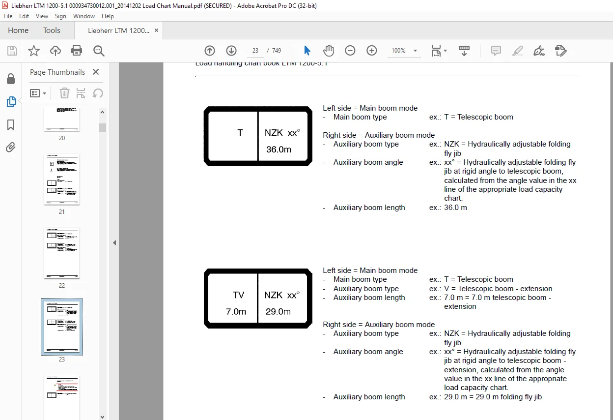
1.7 Additional information and limitations are specified in the operating mode symbol for select
operating modes. See „Limitation descriptions for operating modes“ on page 25.
2. Crane operating mode „Crane supported“
2.1 Before the crane is raised on its supports, the axle suspension must be blocked.
2.2 The sliding arms of the hydraulic support jack must be extended (to a uniform length on both
sides) to the extent stated in the applirope load capacity table.
2.3 The sliding arms must be secured by pins.
2.4 It is necessary to place stable underlay material under the support pads of the support
jacks over a large surface area according to ground conditions.
2.5 All wheels must be raised clear of the ground.
2.6 Use the BluetoothTM Terminal (BTT) to align the crane horizontally. Horizontal positioning
of the crane must also be checked from time to time and adjusted as necessary.
TABLE OF CONTENTS:
Liebherr LTM 1200-5.1 Load Chart Manual 093473 – PDF DOWNLOAD
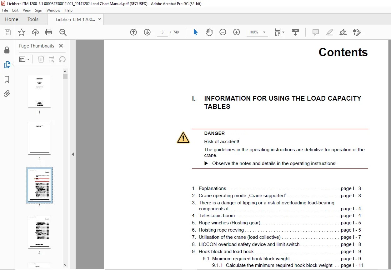
1 Explanations page I – 3
2 Crane operating mode „Crane supported“ page I – 3
3 There is a danger of tipping or a risk of overloading load-bearing
components if: page I – 4
4 Telescopic boom page I – 4
5 Rope winches (Hosting gear) page I – 5
6 Hoisting rope reeving page I – 5
7 Utilisation of the crane (load collective) page I – 7
8 LICCON-overload safety device and limit switch page I – 8
9 Hook block and load hook page I – 9
9 1 Minimum required hook block weight page I – 9
9 1 1 Calculate the minimum required hook block weight page I – 11
9 1 2 Establishing rope weight for rope diameter page I – 11
9 1 3 Establishing the reeving factor page I – 12
9 1 4 Calculation examples page I – 13
9 2 Load capacity, rope pulleys and operating weight page I – 14
9 3 Distance between hook and pulley set in the boom head page I – 15
10 Load reduction where a folding fly jib has been mounted page I – 16
11 Maximum turning speed of the crane’s superstructure with
a nominal load page I – 17
11 1EN 13000 – load charts page I – 17
11 285% – load charts page I – 18
12 Explanation of symbols page I – 19
Hoisting rope reeving page I – 19
Load capacity in metric tons [t] page I – 19
Operating mode page I – 19
Operating mode that can only be operated with accessories! page I – 22
Load handling chart book LTM 1200-5 1
bltm1200-5 1 gc I – 2 /46
Contents
Assembly operating modes page I – 23
Disassembly and assembly of the rear sliding rods
using the standing crane page I – 23
Raising and setting down the telescopic jib into and
out of the holding fixture on the dolly page I – 24
Limitation descriptions for operating modes page I – 25
Characteristic: 1)
– Minimum hoist rope reeving page I – 25
Working radius symbols page I – 26
Telescopic boom length page I – 26
Short code page I – 26
Hoisting rope reeving page I – 27
Auxiliary jib angle page I – 27
Extension conditions of the telescopic boom sections page I – 27
Permissible wind speed page I – 27
Counterweight page I – 28
Crane operation „Crane supported“ page I – 28
Assembly operation „Crane supported wide at the front,
rear free on tyres“ page I – 28
Slewing range page I – 29
13 Wind influences during crane operation page I – 30
13 1Definition of terms page I – 30
13 2Wind influence on the LICCON-overload safety device page I – 32
13 2 1 Wind from the rear page I – 32
13 2 2 Wind from the front page I – 32
13 2 3 Wind from the side page I – 32
13 3Permissible wind speed and surface susceptibility to wind page I – 33
13 3 1 Establishing the maximum permissible wind speed page I – 35
13 3 2 Calculating the maximum permissible wind
speed using a formula
Contact us: [email protected]
PLEASE NOTE:
- This is not a physical manual but a digital manual – meaning no physical copy will be couriered to you. The manual can be yours in the next 2 mins as once you make the payment, you will be directed to the download page IMMEDIATELY.
- This is the same manual used by the dealers inorder to diagnose your vehicle of its faults.
- Require some other service manual or have any queries: please WRITE to us at [email protected]
S.V