Liebherr PR 736-1736 Crawler Dozer Service Manual – PR 736-1736 05 G8.0 16834 | PR 736-1736 4F G8.0 16834
Original price was: $78.95.$33.95Current price is: $33.95.
Liebherr PR 736 Crawler Dozer Service Manual – official factory-level PDF covering models PR 736-1736_05_G8.0 16834 & PR 736-1736_4F_G8.0 16834. 860 pages of technical data, hydraulic schematics, wiring diagrams, maintenance schedules, special tools, and adjustment procedures. Instant PDF download – 189 MB.
Description
Liebherr PR 736-1736_05_G8.0 16834 PR 736-1736_4F_G8.0 16834 Crawler Dozer Service Manual – PDF DOWNLOAD
FILE DETAILS:
Liebherr PR 736-1736_05_G8.0 16834 PR 736-1736_4F_G8.0 16834 Crawler Dozer Service Manual – PDF DOWNLOAD
Language : English
Pages : 860
Downloadable : Yes
File Type : PDF
Size: 189 MB
DESCRIPTION:
Liebherr PR 736-1736 Crawler Dozer Service Manual – PR 736-1736 05 G8.0 16834 | PR 736-1736 4F G8.0 16834
Product ID
Manufacturer: Liebherr-Werk Telfs GmbH
Valid for:
PR 736-1736 05 G8.0 16834
PR 736-1736 4F G8.0 16834
Table of Contents
Liebherr PR 736-1736 Crawler Dozer — Service Manual
PR 736-1736_05_G8.0 16834 | PR 736-1736_4F_G8.0 16834 | 860 Pages
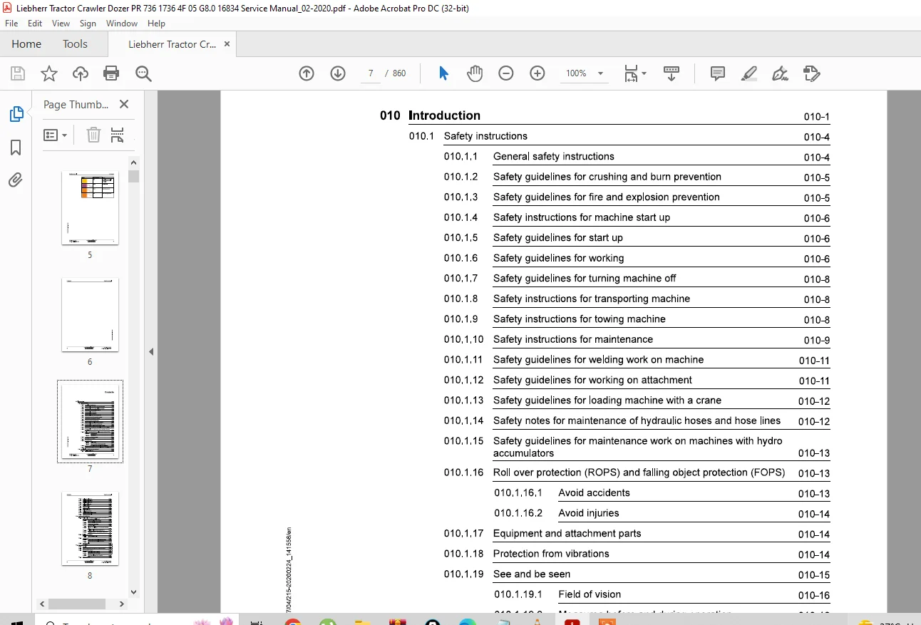
| 010 | Introduction |
| 010.1 | Safety Instructions |
| 010.1.1 | General safety instructions |
| 010.1.2 | Safety guidelines for crushing and burn prevention |
| 010.1.3 | Safety guidelines for fire and explosion prevention |
| 010.1.4 | Safety instructions for machine start up |
| 010.1.5 | Safety guidelines for start up |
| 010.1.6 | Safety guidelines for working |
| 010.1.7 | Safety guidelines for turning machine off |
| 010.1.8 | Safety instructions for transporting machine |
| 010.1.9 | Safety instructions for towing machine |
| 010.1.10 | Safety instructions for maintenance |
| 010.1.11 | Safety guidelines for welding work on machine |
| 010.1.12 | Safety guidelines for working on attachment |
| 010.1.13 | Safety guidelines for loading machine with a crane |
| 010.1.14 | Safety notes for maintenance of hydraulic hoses and hose lines |
| 010.1.15 | Safety guidelines for maintenance on machines with hydro accumulators |
| 010.1.16 | Roll over protection (ROPS) and falling object protection (FOPS) |
| 010.1.16.1 | Avoid accidents |
| 010.1.16.2 | Avoid injuries |
| 010.1.17 | Equipment and attachment parts |
| 010.1.18 | Protection from vibrations |
| 010.1.19 | See and be seen |
| 010.1.19.1 | Field of vision |
| 010.1.19.2 | Measures before and during operation |
| 010.1.20 | Safety notes for Diesel engines with electronic control units |
| 010.1.21 | Safety notes for working on Common Rail System of Diesel engine |
| 010.2 | Special Tools for Maintenance and Repair Work |
| 010.2.1 | Tools – Diesel engine |
| 010.2.2 | Tools – Hydraulic system |
| 010.2.3 | Tools – Hydraulic cylinder |
| 010.2.4 | Tools – Electrical system |
| 010.2.5 | Tools – Travel gearbox |
| 010.2.6 | Tools – Travel gear |
| 010.2.7 | Tension unit tools |
| 010.2.8 | Tools – Equalizer bar |
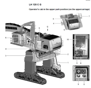
| 010.2.9 | Tools – Operator’s cab |
| 010.2.10 | Tools – Diesel exhaust fluid system |
| 010.2.11 | Assistance system tools |
| 010.3 | Standards and Specifications |
| 010.3.1 | Preload values and tightening torques – screws with standard and fine metric thread (DIN ISO 261) |
| 010.3.1.1 | Scope of application and purpose |
| 010.3.1.2 | Further applicable documentation |
| 010.3.1.3 | Changes and descriptions |
| 010.3.1.4 | Tightening values |
| 010.3.1.5 | Flanges and half flanges for high pressure (standard 62) |
| 010.3.1.6 | Half flange for low pressure (standard 61) |
| 010.3.1.7 | Tightening torques for cutting edges, end bits and adapters |
| 010.3.2 | Installation specifications |
| 010.3.2.1 | Duo cone slipring seals |
| 010.3.3 | Tapping bores |
| 010.3.3.1 | Tapping bores of metric ISO standard threads |
| 010.3.3.2 | Tapping bores of metric ISO fine threads |
| 010.3.4 | Conversion tables |
| 010.4 | Conservation Guidelines |
| 010.4.1 | General |
| 010.4.2 | Taking the machine out of service for an unknown duration |
| 010.4.3 | Shut down of the machine |
| 010.4.3.1 | Shut down for up to 2 months |
| 010.4.3.2 | Shut down for up to 12 months |
| 010.4.3.3 | Shut down for longer than 12 months |
| 010.4.4 | Return to operation |
| 010.4.4.1 | After a shut down of 2 months |
| 010.4.4.2 | After a shut down of 12 months |
| 010.4.4.3 | After shut down of longer than 12 months |
| 010.5 | Repair Welding |
| 010.5.1 | Preparation of cracked part / Preparation of a weld / Treatment of electrodes / Welding technique |
| 010.5.1.1 | Form, thickness, material quality and application of reinforcement sheeting / Welding the reinforcement sheeting |
| 010.5.1.2 | Electrode selection / Steel chart / Welding additives chart |
| 010.6 | Hydraulic Symbols |
| 010.7 | Electrical Symbols |
| 010.8 | Material Weights |
| 020.1 | Overall Machine |
| 020.1.1 | Complete machine – overview |
| 020.2 | Drive Group |
| 020.2.1 | Diesel engine |
| 020.3 | Cooling System |
| 020.3.1 | Gear pump for cooling circuit |
| 020.3.2 | Fan drive gear motor for water, charge air and hydraulic oil cooler |
| 020.4 | Working Hydraulics |
| 020.4.1 | Working hydraulics regulating pump |
| 020.4.2 | Proportional control valve block |
| 020.4.3 | Lift cylinder |
| 020.4.4 | Tilt cylinder |
| 020.5 | Travel Hydraulics |
| 020.5.1 | Gear pump supply |
| 020.5.2 | Variable displacement pump |
| 020.5.3 | Variable displacement motor |
| 020.6 | Hydraulic Components |
| 020.6.1 | Hydraulic tank |
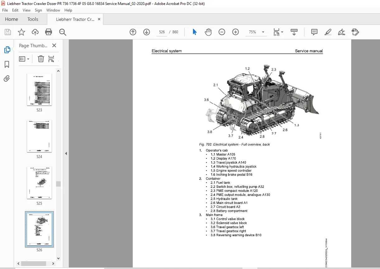
| 020.7 | Electrical System |
| 020.7.1 | Batteries installation |
| 020.8 | Travel Gearbox |
| 020.8.1 | Travel gearbox |
| 020.8.2 | Brake system |
| 020.9 | Travel Gear, Axles, Drive Shafts |
| 020.9.1 | Travel gear frame |
| 020.9.2 | Idler |
| 020.9.3 | Tension unit |
| 020.9.4 | Track roller |
| 020.9.5 | Carrier roller |
| 020.9.6 | Track chain |
| 020.9.7 | Sprocket |
| 020.10 | Working Attachment |
| 020.10.1 | Straight blade |
| 020.10.2 | 6-way blade |
| 020.10.3 | Cutting angle adjustment for blade |
| 020.10.4 | Ripper |
| 030.1 | Maintenance and Inspection Schedule |
| 030.2 | Fill Quantities & Lubrication Schedule |
| 030.2.1 | Recommended lubricants |
| 030.2.2 | Recommended fuel and operating fluids |
| 030.2.3 | Lubrication schedule |
| 030.3 | Lubricants and Fuels |
| 030.3.1 | General information – safety data sheets, technical data sheets, Liebherr standards |
| 030.3.2 | Diesel fuels – Liebherr recommendation |
| 030.3.3 | Engine oils – Stage IV/Tier 4f, Stage V and other emission stages |
| 030.3.4 | Coolant – water requirements, corrosion inhibitor, anti-freeze and corrosion protection agent |
| 030.3.5 | Diesel exhaust fluids – recommendation and minimum quality requirements |
| 030.3.6 | Hydraulic oils – recommendation, quality, oil analysis, filter change, oil change |
| 030.3.7 | Lube oils for travel gearbox – quality, viscosity, oil change |
| 030.3.8 | Oil for duo cone (slipring) seal – travel gear |
| 030.3.9 | Grease and other lubricants |
| 030.3.10 | Oil for hinges and joints |
| 030.3.11 | Oil for axle bearing |
| 030.4 | Maintenance Tasks |
| 030.4.1 | Safety instructions for maintenance |
| 030.4.2 | Maintenance preparations – maintenance position, lifting / lowering operator’s cab |
| 030.4.3 | Overall machine – external checks, lubrication, wiper blade, oil samples, wet cleaning, piston rod protection, taking out of service |
| 030.4.4 | Diesel engine – oil level, oil/filter change, V-belt, fuel system, air filter, DPF, exhaust, electrical (030.4.4.1 – 030.4.4.27) |
| 030.4.5 | Cooling system – coolant level, cleaning, leak check, anti-freeze, coolant change (030.4.5.1 – 030.4.5.5) |
| 030.4.6 | Travel hydraulics – changing supply circuit filter cartridge |
| 030.4.7 | Hydraulic components – oil level, magnetic rod, leak check, oil change, pressure adjustment, return filter (030.4.7.1 – 030.4.7.6) |
| 030.4.8 | Electrical system – lighting, batteries, cable routings, travel drive control (030.4.8.1 – 030.4.8.4) |
| 030.4.9 | Travel gearbox – condition, oil level, oil change, duo cone area (030.4.9.1 – 030.4.9.5) |
| 030.4.10 | Travel gear – bolts, rollers, idler guides, track tension, wear, axle bearing (030.4.10.1 – 030.4.10.6) |
| 030.4.11 | Working attachment – cutting edges, blade centre, bearing wear, screws, ripper tooth tips (030.4.11.1 – 030.4.11.5) |
| 030.4.12 | Cab, heating, A/C – function check, air filter, HVAC specialist inspection, condenser (030.4.12.1 – 030.4.12.4) |
| 030.5 | Testing and Adjustment Checklist |
| 030.5.1 | Adjustment checklist |
| 030.5.2 | Track components check list |
| 030.6 | Check and Adjustment Tasks |
| 030.6.1 | Safety instructions |
| 030.6.2 | Overall machine – preparations, visual inspection, bringing to operating temperature |
| 030.6.3 | Drive group – engine speed controller, adjustment range |
| 030.6.4 | Cooling system – stand-by pressure for fan control, pressure relief valve for fan motor |
| 030.6.5 | Working hydraulics – standby pressure, operating pressure, primary/secondary relief valves, pressure cut-off, hydro accumulator nitrogen fill |
| 030.6.6 | Travel hydraulics – supply pressure, neutral position, high pressure limitation, pressure regulator |
| 030.6.7 | Electrical system – hydrostat calibration, travel joystick, inching brake pedal, brake test, overspeed test, CAN modules, Master5 software/LiFT/factory reset, Free Grade/Definition Grade calibration, lighting duration (030.6.7.1 – 030.6.7.13) |
| 040.1 | Diesel Engine |
| 040.1.1 | Diesel engine – full overview |
| 040.1.2 | Fuel system – overview, fuel quantity sensor, fuel filter, fuel tank |
| 040.1.3 | Air filter system |
| 040.1.4 | Exhaust system – full overview |
| 040.1.5 | Diesel engine mounting |
| 040.2 | Clutch |
| 050.1 | Complete cooling system |
| 050.2 | Cooler Arrangement |
| 050.2.1 | Cambi cooler |
| 050.3 | Hydraulic |
| 050.3.1 | Gear pump |
| 050.3.2 | Gear motor |
| 060.1 | Working hydraulics – full overview |
| 060.2 | Regulating Pump |
| 060.2.1 | Regulating pump – full overview |
| 060.3 | Proportional Control Valve Block |
| 060.3.1 | Proportional control valve block – full overview |
| 060.4 | Hydraulic Cylinders |
| 060.4.1 | Lift cylinder |
| 060.4.2 | Tilt cylinder |
| 070.1 | Complete travel hydraulics |
| 070.2 | Variable Displacement Pump |
| 070.3 | Variable Displacement Motors |
| 070.3.1 | Variable displacement motors – full overview |
| 080.1 | Hydraulic Cylinders |
| 080.1.1 | Lift cylinder |
| 080.1.2 | Tilt cylinder and swing cylinder |
| 080.1.3 | Ripper cylinder |
| 080.1.4 | Cutting angle control cylinder for blade |
| 080.2 | Hydraulic Tank |
| 080.2.1 | Hydraulic tank |
| 100.1 | Inching Brake Pedal |
| 100.1.1 | Speed reduction pedal |
| 110.1 | Electrical system – full overview |
| 110.2 | Lighting System |
| 110.3 | Circuit Diagrams |
| 110.4 | Electrical Components – Operator’s Cab |
| 110.4.1 | Cab electrical components – full overview |
| 110.4.2 | Central control (Master 105) |
| 110.4.3 | Compact control (A 120) |
| 110.4.4 | Travel joystick |
| 110.4.5 | Speed control |
| 110.5 | Electrical Components – Diesel Engine |
| 110.6 | Electrical Components – Main Frame |
| 110.7 | Electrical Components – Compartments |
| 110.7.1 | Battery compartment |
| 110.7.2 | Fuel tank |
| 110.7.3 | Central electrical system compartment |
| 110.7.4 | Hydraulic tank |
| 110.8 | Display Unit |
| 110.9 | Electrical Components – Lidat |
| 110.10 | Electrical Components – Assistance Systems |
| 110.10.1 | Calibrating Free Grade and Definition Grade |
| 110.11 | Electrical Components – Machine Control |
| 110.11.1 | Machine control – Trimble |
| 110.11.2 | Machine control – Leica |
| 110.11.3 | Machine control – Topcon |
| 120.1 | Travel gearbox – overall |
| 120.2 | Brake System |
| 120.3 | Duo Cone Slipring Seal |
| 120.4 | External Oil Supply |
| 130.1 | Travel Gear Frame |
| 130.1.1 | Support frame |
| 130.2 | Idler |
| 130.3 | Tension Unit |
| 130.4 | Tension Unit – Removal |
| 130.4.1.1 | Remove the cover on the track roller frame |
| 130.4.1.2 | Position of tension unit grease nipple |
| 130.4.1.3 | Push the pin in |
| 130.4.1.4 | Removal of cover |
| 130.4.1.5 | Grease nipple with twist guard |
| 130.4.1.6 | Place a mark |
| 130.4.1.7 | Installation of the assembly tool |
| 130.4.1.8 | Adjust the assembly tool |
| 130.4.1.9 | Clamp on the assembly tool |
| 130.4.1.10 | Press in the tension unit |
| 130.4.1.11 | Removal of the tension unit |
| 130.5 | Tension Unit – Installation |
| 130.5.1.1 | Installation |
| 130.5.1.2 | Positioning of left and right travel gear |
| 130.5.1.3 | Press in the tension unit |
| 130.5.1.4 | Venting the tension unit |
| 130.5.1.5 | Installation of cover |
| 130.5.1.6 | Install the cover on the track roller frame |
| 130.6 | Track Roller |
| 130.7 | Carrier Roller |
| 130.8 | Function, Wear and Evaluation |
| 140.1 | Lift cylinder suspension |
| 140.2 | Equaliser Bar |
| 140.3 | Push Frame (inside) |
| 140.4 | Push Frame (outside) |
| 150.1 | Straight blade |
| 150.2 | 6-way blade |
| 150.3 | Ripper |
| 150.4 | Ripper for front equipment – semi-LI-blade |
| 150.5 | Ripper for front equipment – 6-way blade |
| 160.1 | Operator’s Platform |
| 160.1.1 | Operator’s platform installations |
| 160.1.2 | Operator’s platform bearing |
| 160.1.3 | Support cylinder |
| 160.2 | Operator’s Cab |
| 160.2.1 | Operator’s seat with pneumatic comfort suspension |
| 160.3 | Heating, Ventilation, Air Conditioning |
| 160.3.1 | Heating and air conditioning system |
| 160.3.1.1 | Heating, air conditioning and ventilation – full system |
| 190.1 | Refuelling pump |
| 190.2 | Reversible fan drive |
| 200.2 | Testing and Adjustment Software |
| 200.2.1 | Wizard test and adjustment software |
| 200.2.1.1 | General |
| 200.2.1.2 | Symbols |
Official Factory Service Manual
Liebherr PR 736 Crawler Dozer
Service & Repair Manual – PDF Download
Valid for: PR 736-1736_05_G8.0 16834 | PR 736-1736_4F_G8.0 16834
📁 File Details
| Manufacturer | Liebherr-Werk Telfs GmbH |
| Compatible Models | PR 736-1736_05_G8.0 16834 PR 736-1736_4F_G8.0 16834 |
| Language | English |
| Pages | 860 Pages |
| File Type | |
| File Size | 189 MB |
| Delivery | Instant Download |
📋 What This Manual Covers
This is the official Liebherr factory service manual used by authorised dealers and trained technicians worldwide. It provides comprehensive, system-level technical knowledge for the complete maintenance, adjustment, and repair of the Liebherr PR 736 Crawler Dozer.
🔧 Systems Covered (860 Pages)
| Section | System / Topic |
|---|---|
| 010 | Introduction, Safety Instructions, Special Tools, Standards |
| 020 | Technical Data – Engine, Hydraulics, Travel, Electrical |
| 030 | Maintenance, Lubrication, Adjustment & Testing Checklists |
| 040 | Drive Group – Diesel Engine, Fuel System, Air & Exhaust |
| 050 | Cooling System – Cambi Cooler, Gear Pump & Motor |
| 060–080 | Working & Travel Hydraulics – Pumps, Valves, Cylinders, Tank |
| 110 | Electrical System – Wiring, Lighting, CAN Modules, Diagnostics |
| 120–130 | Travel Gearbox, Brake System, Track Gear, Rollers, Idler |
| 140–150 | Steel Components, Working Attachment – Blade, Ripper |
| 160 | Operator’s Cab, Heating, HVAC, Ventilation |
| 190 | Options – Refuelling Pump, Reversible Fan Drive |
| 200 | Service Codes, Diagnostics, Wizard Test & Adjustment Software |
⚡ Why Download From Us
✔ Same manual used by Liebherr dealerships – not a generic third-party reprint
✔ Instant delivery – download within 2 minutes of payment, no waiting for couriers
✔ Secure payment – you are taken directly to the download page after checkout
✔ Searchable PDF – find any topic, part number, or procedure instantly
✔ Support: [email protected] – we respond to every query
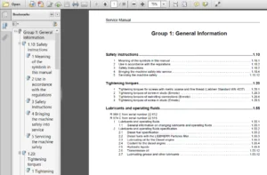
IMAGES PREVIEW OF THE MANUAL:
S.V