Liebherr R 914 C Litronic 1062 1063 1064 1065 Hydraulic Excavator Operating Manual SN 27782 – PDF DOWNLOAD
$28.95
Liebherr R 914 C Litronic 1062 1063 1064 1065 Hydraulic Excavator Operating Manual SN 27782 – PDF DOWNLOAD
Product ID
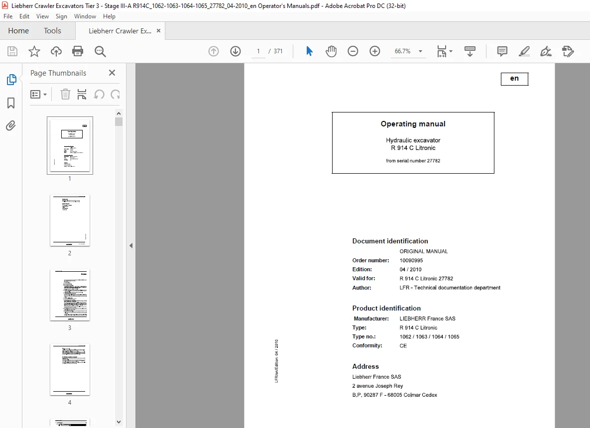
Manufacturer: LIEBHERR France SAS
Type: R 914 C Litronic
Type no.: 1062 / 1063 / 1064 / 1065
Description
Liebherr R 914 C Litronic 1062 1063 1064 1065 Hydraulic Excavator Operating Manual SN 27782 – PDF DOWNLOAD
FILE DETAILS:
Liebherr R 914 C Litronic 1062 1063 1064 1065 Hydraulic Excavator Operating Manual SN 27782 – PDF DOWNLOAD
Language : English
Pages : 371
Downloadable : Yes
File Type : PDF
DESCRIPTION:
Liebherr R 914 C Litronic 1062 1063 1064 1065 Hydraulic Excavator Operating Manual SN 27782 – PDF DOWNLOAD
Product ID
Manufacturer: LIEBHERR France SAS
Type: R 914 C Litronic
Type no.: 1062 / 1063 / 1064 / 1065
Preface:
These operating instructions have been written for the machine operator and for the maintenance personnel of the machine.
They contain:
The operating instructions are to be read and used carefully by all persons who carry out work with or on the machine before putting the machine into service for the first time and later, at regular intervals.
Work with or on the machine includes, for example:
- Operation including setting up and equipping, rectifying malfunctions during the course of work, resolving production dropouts, care, disposal of operating and process materials.
- Maintenance, including maintenance, inspection and repair work.
- Transportation or loading the machine.
The operating instructions allow the machine operator to familiarize themselves with the machine more easily and prevent malfunctions occurring due to improper operation. The observance of the operating and maintenance instructions by maintenance personnel:
- increases reliability in use.
- extends the service life of your machine.
- reduces repair costs and downtime.
The operating instructions belong with the machine for the entire lifetime of the machine. Place a copy in an easily reached position on the cab storage shelf. This copy must be replaced immediately if lost, damaged or unreadable.
The operating and maintenance instructions must be completed by information on current national regulations for accident prevention and protection. In addition to the operating instructions and legally binding regulations on accident prevention which apply in the user country and at point of use, authorized specialist rules for safe and correct working procedures are also to be observed.
These operating and maintenance instructions contain all the information required for operating and maintaining your machine.
- Some illustrations in these operating instructions may depict details and working devices which differ from your machine.
- In some illustrations, protective devices and covers have been removed in the interests of better presentation.
- Improvements, which are always being incorporated into our machines, may result in changes to your machine which are not yet indicated in these operating instructions.
TABLE OF CONTENTS:
Liebherr R 914 C Litronic 1062 1063 1064 1065 Hydraulic Excavator Operating Manual SN 27782 – PDF DOWNLOAD
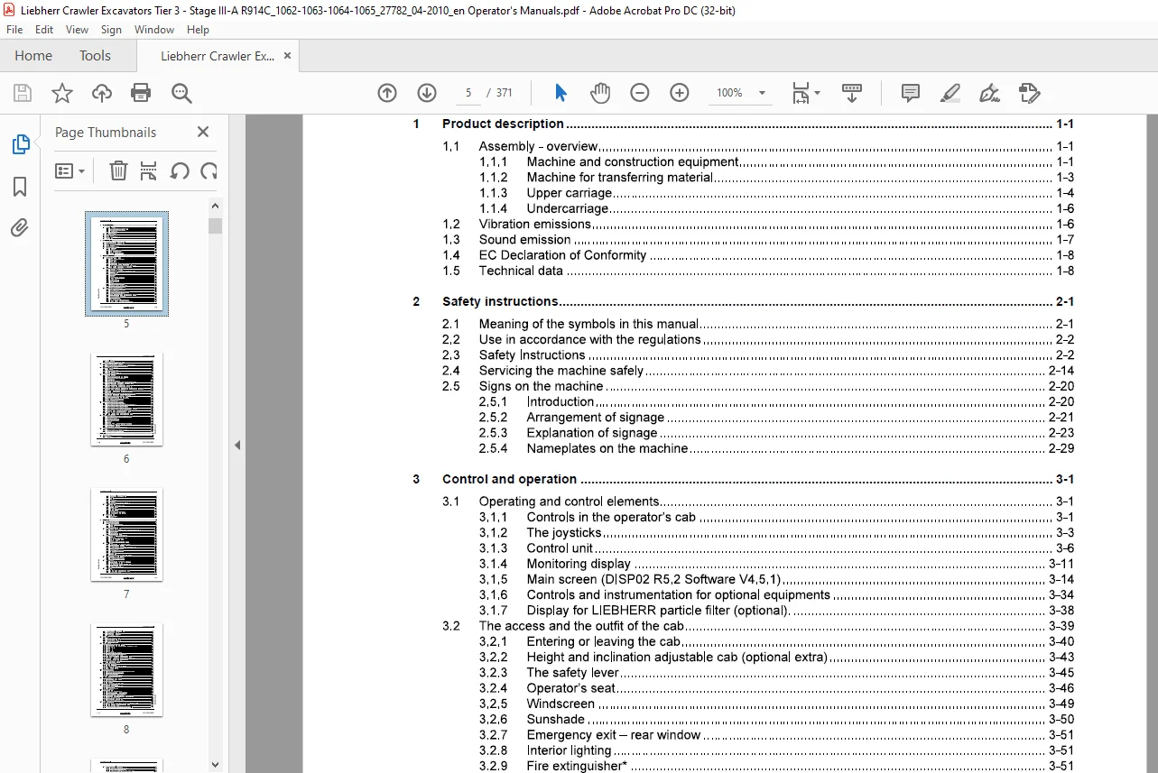
11 Assembly – overview 1-1
111 Machine and construction equipment 1-1
112 Machine for transferring material 1-3
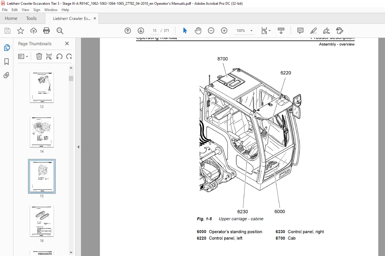
113 Upper carriage 1-4
114 Undercarriage 1-6
12 Vibration emissions 1-6
13 Sound emission 1-7
14 EC Declaration of Conformity 1-8
15 Technical data 1-8
21 Meaning of the symbols in this manual 2-1
22 Use in accordance with the regulations 2-2
23 Safety Instructions 2-2
24 Servicing the machine safely 2-14
25 Signs on the machine 2-20
251 Introduction 2-20
252 Arrangement of signage 2-21
253 Explanation of signage 2-23
254 Nameplates on the machine 2-29
31 Operating and control elements 3-1
311 Controls in the operator’s cab 3-1
312 The joysticks 3-3
313 Control unit 3-6
314 Monitoring display 3-11
315 Main screen (DISP02 R52 Software V451) 3-14
3 16 Controls and instrumentation for optional equipments 3-34
317 Display for LIEBHERR particle filter (optional) 3-38
32 The access and the outfit of the cab 3-39
321 Entering or leaving the cab 3-40
322 Height and inclination adjustable cab (optional extra) 3-43
323 The safety lever 3-45
324 Operator’s seat 3-46
325 Windscreen 3-49
326 Sunshade 3-50
32 7 Emergency exit – rear window 3-51
328 Interior lighting 3-51
329 Fire extinguisher” 3-51
3210 Windscreen wiper 3-52
3211 Lighting 3-54
3212 The heater and air conditioner 3-55
3213 Additional standstill heater (Option) 3-60
3214 Pressurized driver’s cab (option) 3-64
33 Setting the machine into operation 3-66
331 Starting I stopping the machine 3-68
332 Starting the engine 3-70
333 Speed adjustment and operating modes 3-71
334 Notes after starting the engine 3-73
335 Warm-up phase for Diesel engine and hydraulic circuit 3-73
336 Switching the Diesel engine off 3-74
337 indicatorStarting aids 3-75
338 Jump start procedure 3-77
339 Anti-theft device with code key (option) 3-78
3310 Immobilizer with electronic ignition key (option) 3-78
3311 Travel functions 3-80
3312 Drive warning device (optional extra) 3-84
34 Operating the excavator in safety modes 3-85
341 Board E52 for safety mode of Diesel engine & servo control 3-85
342 Safety operation of the main working pumps 3-88
35 Recovering, towing the machine 3-89
351 Pre-requisite 3-89
352 Process preconisations 3-89
353 Other preconisations 3-91
354 With clevis type eylet available 3-91
36 Working with the machine 3-92
361 Low idle automatic 3-97
362 Automatic motorstop after low idle (in option) 3-98
363 The uppercarriage swing movements 3-98
364 Working position 3-100
365 Working attachment control 3-101
366 Lowering the working attachment with the engine shut down 3-103
367 Turning, rotating, bolting and unbolting the add-on unit 3-104
368 Control of the swivel rotator (option) 3-105
369 Lifting magnet control system (optional equipment) 3-107
3610 Control of special equipments via the additional pedals 3-108
3611 Commutation of the controls for an additional user AHS (special equipment) 3-112
3612 Special control system of the joysticks 3-113
3613 Option oil flow reduction for long working attachment 3-115
3614 Dozer blade 3-116
3615 Cut off by end switches of attachment movements (Option) 3-117
3616 Mechanical stanchion cylinder shut-down (option) 3-121
3617 Low pressure protection for boom cylinders 3-124
3618 Use of the excavator for lifting loads overhead 3-125
3619 Overload warning device (Option) 3-126
3620 Mowing bucket (option) 3-128
37 Attaching and dismounting equipment parts 3-129
371 Attaching and dismounting the bucket 3-130
372 Attaching and dismounting the bucket with improved sealing 3-133
373 Attaching and dismounting the grab on stick 3-135
374 Attaching and dismounting the grab on stick 3-138
375 Attaching and dismounting the grab on the industrial stanchion 3-141
376 Attaching and dismounting the stick to the boom 3-143
377 Mechanical quick-change adapter (optional extra) 3-145
378 Hydraulic quick-change adapter (optional extra) 3-150
379 LIKUFIX- hydraulic coupling system (optional extra) 3-156
38 General working methods 3-158
381 Minimum impact working methods for your machine 3-158
382 Preparatory activities 3-159
383 Using a backhoe bucket 3-160
384 Loading a transport vehicle 3-161
385 Skimming 3-162
386 Using a clamshell bucket (earthmoving attachment) 3-163
387 Using a multiple tine grapple (industrial attachment) 3-165 ~
388 Using an hydraulic hammer 3-166 ~
389 Working with large and heavy attachments 3-167 c!;
39 Transport 3-168 g
391 Transporting the machine on a low loader 3-169 ®
392 Loading the machine with a crane 3-171
411 Machine Control system (BST) 4-2
412 Engine control system (PLO-CR) 4-3
413 Keypad 4-6
414 Display 4-6
415 Coding error 4-7
416 Other errors 4-7
417 Error due to warning symbols in SY field 4-7
42 Faults and remedies 4-9
421 Diesel engine and fuel system 4-9
422 Hydraulic system 4-10
423 Transmission 4-11
424 Electrical system 4-11
425 Work equipment 4-12
426 Heating/air-conditioning system 4-12
427 LIEBHERR particles filter system 4-15
43 Fuses and relays 4-16
431 Fuse box E50 4-16
432 A1010 Plate 4-17
51 Servicing the machine safely 5-1
52 Maintenance access doors 5-8
521 Overview of access doors 5-8
522 Door lock 5-9
523 Engine hood lock 5-10
53 Lubricants and operating fluids 5-10
531 General information on changing lubricants and operating fluids 5-10
532 Lubrication chart 5-12
533 Lubricant chart 5-14
534 Operating material chart 5-15
54 Lubricants and operating fluids specification 5-15
541 Dieselfuel 5-15
542 Lubricating oil for the Diesel engine 5-16
543 Coolant for the diesel engine 5-18
544 Hydraulic liquids 5-25
545 Lubricating grease and other lubricants 5-29
55 Diesel engine 5-30
551 Checking the oil level in the diesel engine 5-30
552 Changing the diesel engine oil 5-31
553 Belt for the A/C compressor and alternator installation 5-32
554 Lubricating starter ring gear 5-33
555 Vibration damper 5-34
556 Checking mounting screws 5-34
557 Oil separator 5-35
558 Heater flange 5-36
559 Checking and adjustment of valve clearance 5-36
56 LIEBHERR particles filter (In option) 5-39
561 Drain the condensation water: 5-39
562 Water separator maintenance: 5-39
5 7 Cooling system 5-40
5 71 Checking and cleaning the cooling system 5-40
5 7 2 Checking the coolant level 5-41
5 7 3 Coolant antifreeze and anti-corrosion fluid 5-41
5 7 4 Changing the coolant 5-41
575 Reversible fan drive (option) 5-45
58 Fuel system 5-46
581 Refuelling 5-46
582 Electrical refuelling pump (optional extra) 5-47
583 Draining the fuel tank 5-48
584 Emptying and cleaning the fuel tank 5-49
585 Draining the fuel prefilter 5-49
586 Changing fuel filter cartridges 5-50
587 Bleeding the fuel system 5-52
59 Dry air filter 5-55
591 Changing the main element 5-56
592 Changing the safety element 5-57
593 Monitoring the filtered air line 5-58
594 Spark catcher (option) 5-58
510 Hydraulic system 5-59
5101 Depressurizing the hydraulic system 5-59
5102 Checking the oil level, emptying and refilling the hydraulic tank 5-61
5103 Return-line filter 5-64
5104 Leak oil filter 5-65
5105 Control oil filter 5-66
5106 Control circuit 5-67
510 7 Bleeding the hydraulic pumps 5-67
5108 Removing the intake hose to the pumps 5-68
5109 Bleeding the hydraulic cylinders 5-69
51010 Replacement of the vent filter on the hydraulic tank 5-71
51011 Bypass oil filter for hydraulic system (Special equipment) 5-71
51012 Return oil filter for hydraulic hammer (option) 5-73
51013 Servicing the hydraulic cylinder 5-7 4
51014 Replacing hydraulichoses 5-75
511 Oil changes on components 5-76
5111 General information 5-76
5112 Slewing gear transmission – oil change 5-77
5113 Splitterbox – Oil change 5-78
5114 Travel gear oil change 5-79
512 The track components 5-80
5121 Checking the mounting screws of the track components 5-80
5122 Checking the track chains tension 5-80
5123 Retensioning the track 5-82
5124 Releasing the track chain tension 5-82
5125 Cleaning the track components 5-83
513 Electrical system 5-84
5131 Notes on the electrical system 5-84
5132 Main battery switch 5-85
5133 Battery care 5-85
5134 Slip ring assembly (optional extra) 5-86
514 Heating/air-conditioning system 5-87
5141 Recirculated and fresh air filters 5-87
5142 Heating system 5-88
5143 Air-conditioning system 5-89
515 Greasing the machine 5-91
5151 Centralized lubrication system 5-91
5152 Semi automatic and full automatic systems 5-93
5153 Operation of the semi automatic system 5-93
5154 Operation of the full automatic system 5-95 ° 0
5155 Emergency lubrication with defective lubrication system 5-97 ~
5156 To refill a grease container 5-97 c!;
5157 Changes in the lubrication circuit 5-98 g
5158 Greasing the grab (optional extra) 5-99 ®
516 Quick-change systems 5-100 b!!c:
5161 Greasing the mechanical quick-change adapter (optional extra) 5-100 ~
5162 Hydraulic quick-change adapter (optional extra) 5-100 ~
5163 LIKUFIX (optional extra) 5-101
5164 Checking and maintenance of quick change coupler 5-103
517 Check mounting bolts for tightness 5-104
5171 Mounting bolts of the counterweight 5-105
517 2 Mounting screws of the swing ring 5-105
5173 Mounting screws of the hydraulic oil and fuel tank 5-106
5174 Mounting screws of the swing gear and motor 5-106
518 Drive unit brakes and swing gear brakes 5-107
519 General maintenance points 5-107
519 1 Replacing working parts 5-107
5192 Checking or replacing the teeth on the bucket 5-107
5193 Welding work on the machine 5-109
520 Control and maintenance chart 5-110
IMAGES PREVIEW OF THE MANUAL:
Contact us: [email protected]
https://vimeo.com/836082858?share=copy
PLEASE NOTE:
- This is the same manual used by the dealers to diagnose and troubleshoot your vehicle
- You will be directed to the download page as soon as the purchase is completed. The whole payment and downloading process will take anywhere between 2-5 minutes
- Need any other service / repair / parts manual, please feel free to contact [email protected] . We still have 50,000 manuals unlisted
S.V