Liebherr R 9150 R 9150B 1592 1829 Hydraulic Excavator Operating Manual SN 38036 – PDF DOWNLOAD
Original price was: $86.95.$30.95Current price is: $30.95.
Liebherr R 9150 R 9150B 1592 1829 Hydraulic Excavator Operating Manual SN 38036 – PDF DOWNLOAD
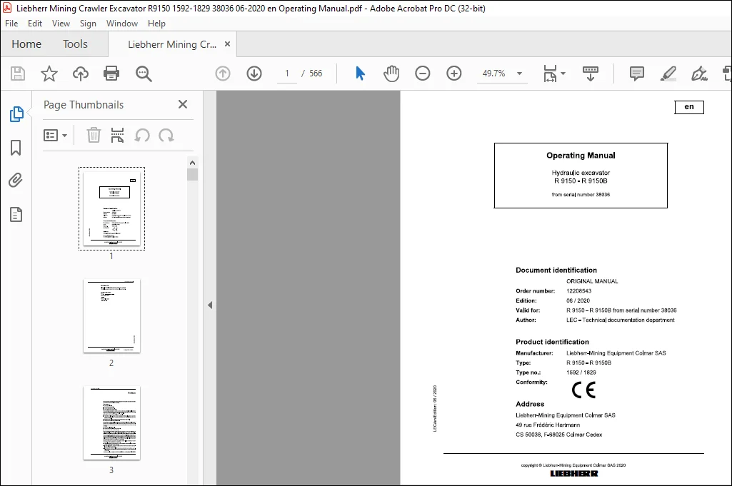
Product identification
Manufacturer: Liebherr-Mining Equipment Colmar SAS
Type: R 9150 R 9150B
Type no.: 1592 1829
Description
Liebherr R 9150 R 9150B 1592 1829 Hydraulic Excavator Operating Manual SN 38036 – PDF DOWNLOAD
FILE DETAILS:
Liebherr R 9150 R 9150B 1592 1829 Hydraulic Excavator Operating Manual SN 38036 – PDF DOWNLOAD
Language : English
Pages : 566
Downloadable : Yes
File Type : PDF
Size: 109 MB
IMAGES PREVIEW OF THE MANUAL:
DESCRIPTION:
Liebherr R 9150 R 9150B 1592 1829 Hydraulic Excavator Operating Manual SN 38036 – PDF DOWNLOAD
Product identification
Manufacturer: Liebherr-Mining Equipment Colmar SAS
Type: R 9150 R 9150B
Type no.: 1592 1829
Preface:
- Operation including setting up and equipping, rectifying malfunctions during the course of work, resolving production dropouts, care, disposal of operating and process materials.
- Maintenance, including maintenance, inspection and repair work.
- Transportation or loading the machine.
- Increases reliability in use.
- Extends the service life of your machine.
- Reduces repair costs and downtime.
- Some illustrations in these operating instructions may depict details and working devices which differ from your machine.
- In some illustrations, protective devices and covers have been removed in the interests of better presentation.
- Improvements, which are always being incorporated into our machines, may result in changes to your machine which are not yet indicated in these operating instructions.
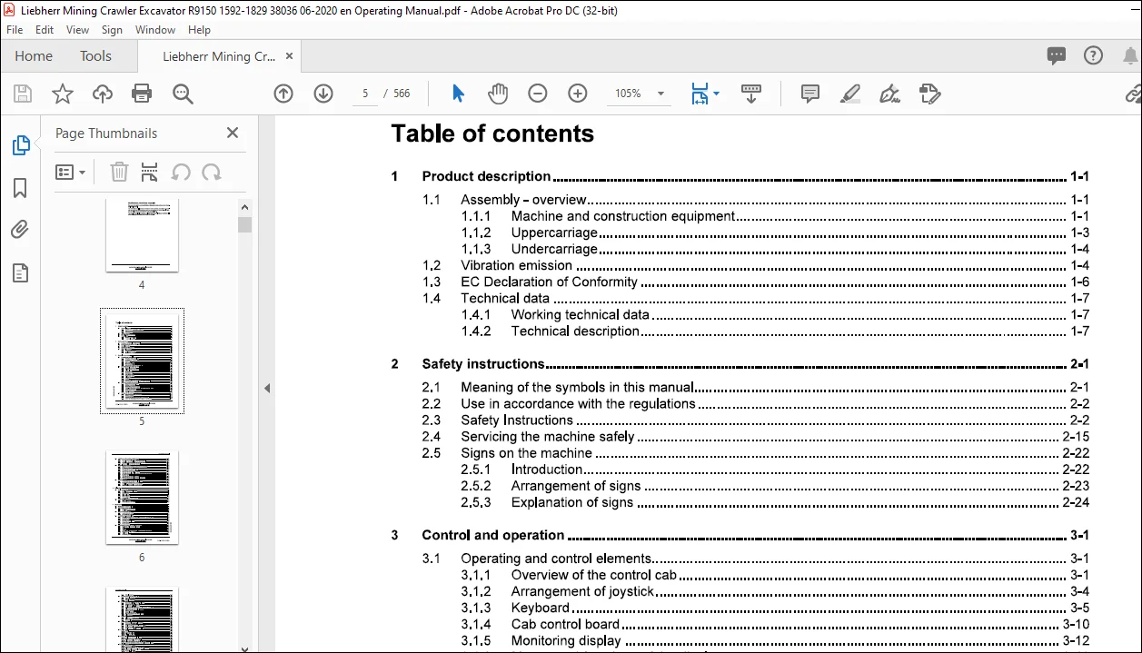
TABLE OF CONTENTS:
Liebherr R 9150 R 9150B 1592 1829 Hydraulic Excavator Operating Manual SN 38036 – PDF DOWNLOAD
1 Product description 1-1
1 1 Assembly- overview 1-1
1 1 1 Machine and construction equipment 1-1
1 1 2 Uppercarriage 1-3
1 1 3 Undercarriage 1-4
1 2 Vibration emission 1-4
1 3 EC Declaration of Conformity 1-6
1 4 Technical data 1-7
1 4 1 Working technical data 1-7
1 4 2 Technical description 1-7
2 Safety instructions 2-1
2 1 Meaning of the symbols in this manual 2-1
2 2 Use in accordance with the regulations 2-2
2 3 Safety Instructions 2-2
2 4 Servicing the machine safely 2-15
2 5 Signs on the machine 2-22
2 5 1 Introduction 2-22
2 5 2 Arrangement of signs 2-23
2 5 3 Explanation of signs 2-24
3 Control and operation 3-1
3 1 Operating and control elements 3-1
3 1 1 Overview of the control cab 3-1
3 1 2 Arrangement of joystick 3-4
3 1 3 Keyboard 3-5
3 1 4 Cab control board 3-10
3 1 5 Monitoring display 3-12
3 1 6 Menus and functions of the display 3-13
3 2 The access and the outfit of the cab 3-41
3 2 1 Enter or leave the cab 3-43
3 2 2 Tilting operator cab (optional) 3-47
3 2 3 Safety lever 3-50
3 2 4 Operator’s seat 3-51
3 2 5 Emergency exit 3-57
3 2 6 Fire extinguisher 3-58
3 2 7 Windscreen wiper 3-60
3 2 8 Field of view 3-62
3 2 9 Lighting 3-63
3 2 10 Heating/air-conditioning system 3-66
3 2 11 Pressurization/reinforced filtration system (optional) 3-75
3 3 Setting the machine into operation 3-75
3 3 1 Start and stop the machine 3-77
3 3 2 Starting aids (optional) 3-83
3 3 3 Preheating procedure (optional) 3-85
3 3 4 Warm-up procedure for Diesel engine and hydraulic circuit 3-93
0 3 3 5 Jump start procedure 3-95
0 3 3 6 Emergency and safety operations 3-96
‘5 3 3 7 Travel movements 3-107
Working with the machine 3-110
3 4 1 Uppercarriage swing movements 3-117
3 4 2 Working position 3-119
3 4 3 Joystick functions when setting up the machine 3-119
3 4 4 Lower the attachment when the engine is not running 3-131
3 5 Attaching and dismounting equipment parts 3-132
3 5 1 Use a quick coupler (optional) 3-133
3 5 2 Grapple or shear installed on the stick (optional) 3-135
3 5 3 Hydraulic hammer installed on the stick (optional) 3-139
3 5 4 Shear installed on the boom (optional) 3-142
3 6 General working methods 3-144
3 6 1 Minimum impact working methods for your machine 3-144
3 6 2 Preparatory activities 3-144
3 6 3 Working with the backhoe bucket 3-145
3 6 4 Loading the transport vehicle 3-147
3 6 5 Working with the shovel type bucket 3-147
3 6 6 Working with the clamshell bucket (construction equipment) 3-149
3 6 7 Hoisting work 3-151
3 6 8 Working with the hydraulic hammer 3-152
3 6 9 Working with the grapple (industrial equipment) 3-153
3 6 10 Skimming 3-154
3 7 Transport 3-155
3 7 1 Transporting the machine on a low loader 3-156
3 7 2 Loading the machine with a crane 3-158
3 7 3 Travelling procedures for mining machine 3-159
3 7 4 Excavator lifting and lashing operations 3-162
4 Malfunctions 4-1
4 1 Faults and remedies 4-2
4 1 1 Diesel engine and fuel system 4-2
4 1 2 Hydraulic system 4-9
4 1 3 Transmission 4-9
4 1 4 Electrical system 4-10
4 1 5 Work equipment 4-10
4 1 6 Heating/air-conditioning system 4-10
4 2 Fuses and relays 4-12
4 2 1 Electrical box E50 4-13
4 2 2 Cab connection box E1005 4-15
5 Maintenance 5-1
5 1 Servicing the machine safely 5-1
5 2 Maintenance access doors 5-8
5 2 1 Overview of access doors 5-8
5 2 2 Door lock 5-9
5 3 Maintenance anchor points 5-9
5 3 1 Approved anchor points 5-10
5 3 2 Use the anchor points 5-15
5 4 Lubricants and operating fluids 5-15
5 4 1 General information on changing lubricants and operating fluids 5-15
5 4 2 Lubrication chart 5-17
5 4 3 Lubricant chart 5-19
5 4 4 Operating material chart 5-20
5 4 5 Service station 5-20 ~
5 4 6 Grease devices 5-22 C”II 5 5 Lubricating and operating material specifications 5-23 8–
5 5 1 Lubricating oil for the Diesel engine 5-23 g
5 5 2 Fuel 5-24 :;:::;
5 5 3 Coolant 5-24 ;
5 5 4 Hydraulic oil specifications for LIEBHERR Mining excavators 5-24 c3
5 5 5 Swing and travel gear oils 5-30 ~
5 5 6 Splitterbox oil 5-32
5 5 7 Lubricating grease 5-32
5 5 8 Other lubricants 5-34
5 6 Condition monitoring with oil analysis 5-35
5 6 1 General information 5-35
5 6 2 Oil sampling 5-35
5 6 3 Sample processing 5-43
5 7 Diesel engine 5-47
5 7 1 Check the oil level of the Diesel engine 5-47
5 7 2 Change the Diesel engine oil 5-48
5 7 3 Replace the oil filter elements 5-50
5 7 4 Replace the filter element of the oil separator (if installed) 5-51
5 7 5 Belts and tensioning devices 5-51
5 7 6 Check and adjust the valve clearance 5-52
5 7 7 Vibration damper 5-52
5 7 8 Heater flange (optional) 5-52
5 7 9 Mounting screws of the Diesel engine 5-52
5 7 10 Elastic bedding 5-53
5 8 Splitterbox 5-54
5 8 1 Splitterbox mounting screws 5-54
5 8 2 Elastic bedding 5-56
5 8 3 Breather filter 5-57
5 9 Cooling system 5-57
5 9 1 Check and clean the cooling system 5-57
5 9 2 Check the coolant level 5-58
5 9 3 Coolant antifreeze and anti-corrosion fluid 5-59
5 9 4 Change the coolant 5-59
5 9 5 Replace the coolant filter (if installed) 5-61
5 10 Fuel system 5-62
5 10 1 Refuel 5-62
5 10 2 Drain the fuel tank 5-63
5 10 3 Clean the fuel tank 5-64
5 10 4 Fuel filtering system 5-65
5 11 Dry air filter 5-76
5 11 1 Replace the primary filter element 5-78
5 11 2 Replace the safety element 5-79
5 11 3 Clean the precleaner air channels 5-80
5 11 4 Clean the housing of the air filter elements 5-81
5 11 5 Check the air intake system, hoses, elbow tubes, clamps 5-82
5 12 Hydraulic system 5-82
5 12 1 Preparatory activities 5-83
5 12 2 Check the oil level in the hydraulic tank 5-83
5 12 3 Release the pressure from the hydraulic system 5-84
5 12 4 Drain and fill the hydraulic tank 5-86
5 12 5 Hydraulic oil coolers 5-88
5 12 6 Leak oil filter and return filter 5-88
5 12 7 Piloting and replenishing oil filters 5-89
5 12 8 High pressure filters in working circuit 5-91
5 12 9 Servo oil circuit 5-94
5 12 10 Remove the intake hoses from the pumps 5-95
5 12 11 Bleed the hydraulic pumps 5-96
5 12 12 Bleed the hydraulic cylinders 5-98
5 12 13 Bleed the valve blocks 5-98
5 12 14 Return-line filter for the hydraulic hammer (optional) 5-99
5 12 15 Oil cooler protection filters (optional equipment) 5-101
5 12 16 Servicing the hydraulic cylinder 5-102
5 12 17 Replacement of the hydraulic hoses 5-103
5 12 18 Progressive criss-cross tightening procedure 5-106
5 13 Oil changes on components 5-107
5 13 1 General information 5-107
copyright© Liebherr-Mining Equipment Colmar SAS 2020
R 9150- R 9150B / 12208543
MJFCIFSS
Operating Manual
5 13 2 Swing gear – Oil change 5-108
5 13 3 Travel gear – Oil change 5-111
5 13 4 Swing gears and travel gears flushing 5-113
5 13 5 Splitterbox – Oil change 5-114
5 14 Track components 5-115
5 14 1 Check the track components mounting 5-115
5 14 2 Check the track tension 5-121
5 14 3 Increase the track tension 5-122
5 14 4 Decrease the track tension 5-123
5 14 5 Clean the travel gear 5-124
5 14 6 Carrier rails for track chain (optional) 5-124
5 15 Electrical system 5-126
5 15 1 Notes on the electrical system 5-126
5 15 2 Batteries switches and EDC connectors 5-126
5 15 3 Battery care 5-128
5 15 4 Electrical components location 5-130
5 16 Heating/air-conditioning system 5-131
5 16 1 Heating system 5-132
5 16 2 Air-conditioning system 5-134
5 16 3 Additional maintenance work 5-137
5 16 4 Additional cab heater (optional) 5-138
5 16 5 Cab preheating system (optional) 5-138
5 17 Cab pressurization (optional) 5-138
5 17 1 Aeration device (optional) 5-138
5 17 2 Pressurization/reinforced filtration system (optional) 5-139
5 18 Greasing the machine 5-140
5 18 1 Lubrication of attachment bearing points 5-140
5 18 2 Lubrication of special tools (optional) 5-140
5 19 Check mounting bolts for tightness 5-140
5 19 1 Counterweight mounting bolts 5-141
5 19 2 Mounting bolts of the swing ring 5-142
5 19 3 Mounting bolts of the fuel tank 5-142
5 19 4 Mounting bolts of the hydraulic tank 5-143
5 19 5 Mounting bolts of swing gear and swing motor 5-144
5 19 6 Mounting bolts of hydraulic pumps 5-145
5 19 7 Mounting bolts of the cab 5-145
5 19 8 Mounting bolts of the cab elevation (if installed) 5-147
5 19 9 Mounting bolts of the tilting operator cab (optional) 5-147
5 19 10 Mounting bolts of side frames 5-149
5 20 Quick coupler (optional) 5-149
5 21 Drive unit brakes and swing gear brakes 5-149
5 22 Fire suppression system 5-150
5 23 Starting aids (optional) 5-150
5 24 General maintenance points 5-153
5 24 1 Replacing working parts 5-153
5 24 2 Welding work on the machine 5-153
5 25 Control and maintenance chart 5-154
5 25 1 General information 5-154
5 25 2 How to use the maintenance chart 5-155 ~
5 25 3 Daily Maintenance Schedule – R9150 5-156 ~
5 25 4 250 Hours Maintenance Schedule – R9150 5-162 8
5 25 5 500 Hours Maintenance Schedule – R9150 5-164 g
5 25 6 1000 Hours Maintenance Schedule – R9150 5-171 :e
5 25 7 2000 Hours Maintenance Schedule – R9150 5-179 ~ i;:
6 UJ Appendix 6-1 1
6 1 Visual check of the hydraulic hoses 6-1
6 1 1 Preface 6-1
Operating Manual
6 1 2 General information 6-2
6 1 3 Components functions 6-4
6 1 4 Recommendations for hose assembly maintenance 6-5
6 2 Cleaning procedure for hydraulic circuits 6-9
6 2 1 Preface 6-9
6 2 2 General information about hydraulic oil contamination 6-9
6 2 3 General cleaning procedure 6-11
6 2 4 Location of the hydraulic tank filters 6-11
6 2 5 Working pumps circuit 6-12
6 2 6 Swing circuit 6-18
6 2 7 Cooling pumps circuit 6-21
6 2 8 Travel motors circuit 6-25
6 2 9 Backhoe cylinders lines 6-28
6 2 10 Shovel cylinders lines 6-34
6 2 11 Clean the hydraulic tank 6-43
6 2 12 Restart the machine 6-43
6 2 13 Monitor the restarted machine 6-45
6 3 Centralized lubrication system 6-45
Customer Support: [email protected]
PLEASE NOTE:
- This is not a physical manual but a digital manual – meaning no physical copy will be couriered to you. The manual can be yours in the next 2 mins as once you make the payment, you will be directed to the download page IMMEDIATELY.
- This is the same manual used by the dealers inorder to diagnose your vehicle of its faults.
- Require some other service manual or have any queries: please WRITE to us at [email protected]
S.V