Liebherr R 9150- R 9150B Hydraulic excavator Operating Manual 38036 – PDF DOWNLOAD
Original price was: $78.00.$30.95Current price is: $30.95.
Liebherr R 9150- R 9150B Hydraulic excavator Operating Manual 38036 – PDF DOWNLOAD
Product identification
Manufacturer: Liebherr-Werk Bischofshofen GmbH
Type: R 9150 – R 9150B
Type no.:1592/1829
from serial number:38036
Description
Liebherr R 9150- R 9150B Hydraulic excavator Operating Manual 38036 – PDF DOWNLOAD
FILE DETAILS:
Liebherr R 9150- R 9150B Hydraulic excavator Operating Manual 38036 – PDF DOWNLOAD
Language : English
Pages : 568
Downloadable : Yes
File Type : PDF
Size: 115 MB
DESCRIPTION:
Liebherr R 9150- R 9150B Hydraulic excavator Operating Manual 38036 – PDF DOWNLOAD
Product identification
Manufacturer: Liebherr-Werk Bischofshofen GmbH
Type: R 9150 – R 9150B
Type no.:1592/1829
from serial number:38036
Preface
This operating manual has been written for the driver and for the maintenance personnel of the machine.
It contains the following descriptions:
- Chapter 1 – Product description
- Chapter 2 – Safety regulations
- Chapter 3 – Handling and operation
- Chapter 4 – Malfunctions
- Chapter 5 – Maintenance
This operating manual must be carefully read before initial operation and should be read and used later at regular intervals by anyone who carries out work on the machine.
Working with or on the machine includes:
- Operation, including equipping, troubleshooting during operation, removing production debris, maintenance, removing operating and auxiliary materials.
- Servicing, including maintenance, inspection, and repairs.
- Transport or loading the machine.
This manual helps the driver to become acquainted with the machine and prevents malfunctions due to incorrect operation.
Observation of the operating and maintenance manual by maintenance staff:
- Increases reliability during operation.
- Extends the service life of your machine.
- Reduces repair costs and downtime.
This manual must be kept with the machine. Make sure a copy is always kept in the glove compartment of the driver’s cab.
In addition to the operating and maintenance manual, follow the instructions based on existing national accident prevention and environmental protection regulations.
In addition to the operating manual and applicable national and local legal accident prevention rules, observe the recognized technical regulations for safe and correct operation.
This operating and maintenance manual contains all the information you need to operate and service your machine.
- Some illustrations in this manual may show details and equipment that are different from those on your machine.
On some pictures, protective devices and covers have been removed for a better view.
We constantly make improvements to our machines, which means there may have been modifications to your machine that are not mentioned in this manual.
However, if you should require explanations or information, the Liebherr technical information and customer services departments will be happy to provide assistance.
IMAGES PREVIEW OF THE MANUAL:
TABLE OF CONTENTS:
Liebherr R 9150- R 9150B Hydraulic excavator Operating Manual 38036 – PDF DOWNLOAD
Product description 1-1
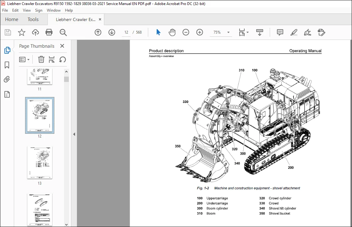
1 1 Assembly- overview 1-1
1 1 1 Machine and construction equipment 1-1
1 1 2 Uppercarriage 1-3
1 1 3 Undercarriage 1-4
1 2 Vibration emission 1-4
1 3 EC Declaration of Conformity 1-6
1 4 Technical data 1-7
1 4 1 Working technical data 1-7
1 4 2 Technical description 1-7
2 Safety instructions 2-1
2 1 Meaning of the symbols in this manual 2-1
2 2 Use in accordance with the regulations 2-2
2 3 Safety Instructions 2-2
2 4 Servicing the machine safely 2-15
2 5 Signs on the machine 2-22
2 5 1 Introduction 2-22
2 5 2 Arrangement and explanations of signs 2-23
3 Control and operation 3-1
3 1 Operating and control elements 3-1
3 1 1 Overview of the control cab 3-1
3 1 2 Arrangement of joystick 3-4
3 1 3 Keyboard 3-4
3 1 4 Cab control board 3-10
3 1 5 Monitoring display 3-11
3 1 6 Menus and functions of the display 3-12
3 2 The access and the outfit of the cab 3-40
3 2 1 Enter or leave the cab 3-42
3 2 2 Tilting operator cab (optional equipment) 3-46
3 2 3 Safety lever 3-49
3 2 4 Operator’s seat 3-50
3 2 5 Emergency exit 3-56
3 2 6 Fire extinguisher 3-57
3 2 7 Windscreen wiper 3-59
3 2 8 Field of view 3-61
3 2 9 Lighting 3-62
3 2 10 Heating/air-conditioning system 3-65
3 2 11 Pressurization/reinforced filtration system (optional) 3-74
3 3 Setting the machine into operation 3-74
3 3 1 Start and stop the machine 3-76
3 3 2 Starting aids (optional) 3-83
3 3 3 Preheating procedure (optional) 3-85
Working with the machine 3-110
3 4 1 Uppercarriage swing movements 3-117
3 4 2 Working position 3-119
3 4 3 Joystick functions when setting up the machine 3-119
3 4 4 Lower the attachment when the engine is not running 3-131
3 5 Attaching and dismounting equipment parts 3-132
3 5 1 General instructions 3-133
3 5 2 Set the configuration of the hydraulic supply lines 3-133
3 5 3 Install a quick coupler (optional equipment) on and remove it from the stick 3-135
3 5 4 Attach a non-rotary tool on and remove it from a quick coupler (optional equipments) 3-135
3 5 5 Attach a rotary tool on and remove it from a quick coupler (optional equipments) 3-136
3 5 6 Install a grapple or a shear (optional equipment) on and remove it from the stick 3-138
3 5 7 Install a hydraulic hammer (optional equipment) on and remove it from the stick 3-141
3 5 8 Select the special tool 3-143
3 5 9 Install a shear (optional equipment) on and remove it from the boom 3-144
3 6 General working methods 3-145
3 6 1 Minimum impact working methods for your machine 3-145
3 6 2 Preparatory activities 3-146
3 6 3 Working with the backhoe bucket 3-147
3 6 4 Loading the transport vehicle 3-148
3 6 5 Working with the shovel type bucket 3-149
3 6 6 Working with the clamshell bucket (construction equipment) 3-151
3 6 7 Hoisting work 3-152
3 6 8 Working with the hydraulic hammer 3-153
3 6 9 Working with the grapple (industrial equipment) 3-155
3 6 10 Skimming 3-156
3 7 Transport 3-156
3 7 1 Transporting the machine on a low loader 3-157
3 7 2 Loading the machine with a crane 3-160
3 7 3 Travelling procedures for mining machine 3-161
3 7 4 Excavator lifting and lashing operations 3-163
4 Malfunctions 4-1
4 1 Faults and remedies 4-2
4 1 1 Diesel engine and fuel system 4-2
4 1 2 Hydraulic system 4-9
4 1 3 Transmission 4-9
4 1 4 Electrical system 4-10
4 1 5 Work equipment 4-10
4 1 6 Heating/air-conditioning system 4-10
4 2 Fuses and relays 4-12
4 2 1 Electrical box E50 4-13
4 2 2 Cab connection box E1005 4-15
5 Maintenance 5-1
5 1 Servicing the machine safely 5-1
5 2 Access points for the maintenance 5-7
5 2 1 Access points overview 5-7
5 2 2 Door lock 5-9
5 2 3 Support device for the tilting operator cab (optional equipment) 5-9
5 3 Maintenance anchor points 5-10
5 3 1 Approved anchor points 5-10
5 3 2 Use the anchor points 5-15
5 4 Lubricants and operating fluids 5-15 ~
5 4 1 General information on changing lubricants and operating fluids 5-15 ~
5 4 2 Lubrication chart 5-17 8
5 4 3 Lubricant chart 5-19 c
0 5 4 4 Operating material chart 5-20 :;:::;
5 4 5 Service station 5-20 ;
5 4 6 Grease devices 5-22 c3
5 5 Lubricating and operating material specifications 5-23 ~
5 5 1 Lubricating oil for the Diesel engine 5-23
5 5 2 Fuel 5-24
5 5 3 Coolant 5-24
5 5 4 Hydraulic oil specifications for LIEBHERR Mining excavators 5-24
5 5 5 Swing and travel gear oils 5-30
5 5 6 Splitterbox oil 5-32
5 5 7 Lubricating grease 5-32
5 5 8 Other lubricants 5-34
5 6 Condition monitoring with oil analysis 5-35
5 6 1 General information 5-35
5 6 2 Oil sampling 5-35
5 6 3 Sample processing 5-43
5 7 Diesel engine 5-47
5 7 1 Check the oil level of the Diesel engine 5-47
5 7 2 Change the Diesel engine oil 5-48
5 7 3 Replace the oil filter elements 5-50
5 7 4 Replace the filter element of the oil separator (if installed) 5-51
5 7 5 Belts and tensioning devices 5-51
5 7 6 Check and adjust the valve clearance 5-52
5 7 7 Vibration damper 5-52
5 7 8 Heater flange (optional) 5-52
5 7 9 Mounting screws of the Diesel engine 5-52
5 7 10 Elastic bedding 5-53
5 8 Splitterbox 5-54
5 8 1 Splitterbox mounting screws 5-54
5 8 2 Elastic bedding 5-56
5 8 3 Breather filter 5-57
5 9 Cooling system 5-57
5 9 1 Check and clean the cooling system 5-57
5 9 2 Check the coolant level 5-58
5 9 3 Coolant antifreeze and anti-corrosion fluid 5-59
5 9 4 Change the coolant 5-59
5 9 5 Replace the coolant filter (if installed) 5-61
5 10 Fuel system 5-62
5 10 1 Refuel 5-62
5 10 2 Drain the fuel tank 5-63
5 10 3 Clean the fuel tank 5-64
5 10 4 Fuel filtering system 5-65
5 11 Dry air filter 5-76
5 11 1 Replace the primary filter element 5-78
5 11 2 Replace the safety element 5-79
5 11 3 Clean the precleaner air channels 5-80
5 11 4 Clean the housing of the air filter elements 5-81
5 11 5 Check the air intake system, hoses, elbow tubes, clamps 5-82
5 12 Hydraulic system 5-82
5 12 1 Preparatory activities 5-83
5 12 2 Check the oil level in the hydraulic tank 5-84
5 12 3 Release the pressure from the hydraulic system 5-85
5 12 4 Drain and fill the hydraulic tank 5-86
5 12 5 Hydraulic oil coolers 5-89
5 12 6 Leak oil filter and return filter 5-89
5 12 7 Piloting and replenishing oil filters 5-90
5 12 8 High pressure filters in working circuit 5-92
5 12 9 Servo oil circuit 5-95
5 12 10 Remove the intake hoses from the pumps 5-96
5 12 11 Bleed the hydraulic pumps 5-97
5 12 12 Bleed the hydraulic cylinders 5-99
5 12 13 Bleed the valve blocks 5-99
5 12 14 Return-line filter for the hydraulic hammer (optional) 5-100
5 12 15 Oil cooler protection filters (optional equipment) 5-102
5 12 16 Servicing the hydraulic cylinder 5-103
5 12 17 Replacement of the hydraulic hoses 5-104
5 12 18 Progressive criss-cross tightening procedure 5-107
5 13 Oil changes on components 5-108
5 13 1 General information 5-108
5 13 2 Swing gear – Oil change 5-109
5 13 3 Travel gear- Oil change 5-112
5 13 4 Swing gears and travel gears flushing 5-114
5 13 5 Splitterbox – Oil change 5-115
5 14 Track components 5-116
5 14 1 Check the track components mounting 5-116
5 14 2 Check the track tension 5-123
5 14 3 Increase the track tension 5-123
5 14 4 Decrease the track tension 5-124
5 14 5 Clean the travel gear 5-125
5 14 6 Carrier rails for track chain (optional) 5-125
5 15 Electrical system 5-127
5 15 1 Notes on the electrical system 5-127
5 15 2 Batteries switches and EDC connectors 5-128
5 15 3 Battery care 5-129
5 15 4 Electrical components location 5-131
5 16 Heating/air-conditioning system 5-132
5 16 1 Heating system 5-133
5 16 2 Air-conditioning system 5-135
5 16 3 Additional maintenance work 5-138
5 16 4 Additional cab heater (optional) 5-139
5 16 5 Cab preheating system (optional equipment) 5-139
5 17 Cab pressurization (optional) 5-139
5 17 1 Aeration device (optional) 5-139
5 17 2 Pressurization/reinforced filtration system (optional) 5-140
5 18 Greasing the machine 5-141
5 18 1 Lubrication of attachment bearing points 5-141
5 18 2 Lubrication of special tools (optional) 5-141
5 19 Check mounting bolts for tightness 5-141
5 19 1 Counterweight mounting bolts 5-142
5 19 2 Mounting bolts of the swing ring 5-143
5 19 3 Mounting bolts of the fuel tank 5-143
5 19 4 Mounting bolts of the hydraulic tank 5-144
5 19 5 Mounting bolts of swing gear and swing motor 5-145
5 19 6 Mounting bolts of hydraulic pumps 5-146
5 19 7 Mounting bolts of the cab 5-146
5 19 8 Mounting bolts of the cab elevation (if installed) 5-148
5 19 9 Mounting bolts of the tilting operator cab (optional) 5-148
5 19 10 Mounting bolts of side frames 5-150
5 20 Quick coupler ( optional) 5-150
5 21 Drive unit brakes and swing gear brakes 5-150
5 22 Fire suppression system 5-151
5 23 Starting aids (optional) 5-151
5 24 General maintenance points 5-154 ~
5 24 1 Replacing working parts 5-154 ~
5 24 2 Welding work on the machine 5-154 8
5 25 Control and maintenance chart 5-155 g
5 25 1 General information 5-155 ~
5 25 2 How to use the maintenance chart 5-156 i;:
5 25 3 Daily Maintenance Schedule – R9150 5-157 ~
5 25 4 250 Hours Maintenance Schedule – R9150 5-163 ~
5 25 5 500 Hours Maintenance Schedule – R9150 5-165
5 25 6 1000 Hours Maintenance Schedule – R9150 5-172
5 25 7 2000 Hours Maintenance Schedule – R9150 5-180
6 Appendix 6-1
6 1 Visual check of the hydraulic hoses 6-1
6 1 1 Preface 6-1
6 1 2 General information 6-2
6 1 3 Components functions 6-4
6 1 4 Recommendations for hose assembly maintenance 6-5
6 2 Cleaning procedure for hydraulic circuits 6-9
6 2 1 Preface 6-9
6 2 2 General information about hydraulic oil contamination 6-9
6 2 3 General cleaning procedure 6-11
6 2 4 Location of the hydraulic tank filters 6-11
6 2 5 Working pumps circuit 6-12
6 2 6 Swing circuit 6-18
6 2 7 Cooling pumps circuit 6-21
6 2 8 Travel motors circuit 6-25
6 2 9 Backhoe cylinders lines 6-28
6 2 10 Shovel cylinders lines 6-34
6 2 11 Clean the hydraulic tank 6-43
6 2 12 Restart the machine 6-43
6 2 13 Monitor the restarted machine 6-45
6 3 Centralized lubrication system 6-45-
Customer Support: [email protected]
PLEASE NOTE:
- This is the SAME exact manual used by your dealers to fix your vehicle.
- The same can be yours in the next 2-3 mins as you will be directed to the download page immediately after paying for the manual.
- Any queries / doubts regarding your purchase, please feel free to contact [email protected]
S.M