Liebherr R 9150 – R 9150B Hydraulic Excavator Operating Manual SN 30614 – PDF DOWNLOAD
$31.95
Liebherr R 9150 – R 9150B Hydraulic Excavator Operating Manual SN 30614 – PDF DOWNLOAD
Description
Liebherr R 9150 – R 9150B Hydraulic Excavator Operating Manual SN 30614 – PDF DOWNLOAD
FILE DETAILS:
Liebherr R 9150 – R 9150B Hydraulic Excavator Operating Manual SN 30614 – PDF DOWNLOAD
Language : English
Pages : 594
Downloadable : Yes
File Type : PDF
IMAGES PREVIEW OF THE MANUAL:
DESCRIPTION:
Liebherr R 9150 – R 9150B Hydraulic Excavator Operating Manual SN 30614 – PDF DOWNLOAD
Preface:
maintenance personnel of the machine.
They contain:
who carry out work with or on the machine before putting the machine into service
for the first time and later, at regular intervals.
Work with or on the machine includes, for example:
course of work, resolving production dropouts, care, disposal of operating and
process materials.
– Maintenance, including maintenance, inspection and repair work.
– Transportation or loading the machine.
machine more easily and prevent malfunctions occurring due to improper operation.
- The operating instructions belong with the machine for the entire lifetime ofthe machine. Place a copy in an easily reached position on the cab storageshelf. This copy must be replaced immediately if lost, damaged or unreadable.
- The operating and maintenance instructions must be completed by information oncurrent national regulations for accident prevention and protection. In addition to the
operating instructions and legally binding regulations on accident prevention which
apply in the user country and at point of use, authorized specialist rules for safe and
correct working procedures are also to be observed.
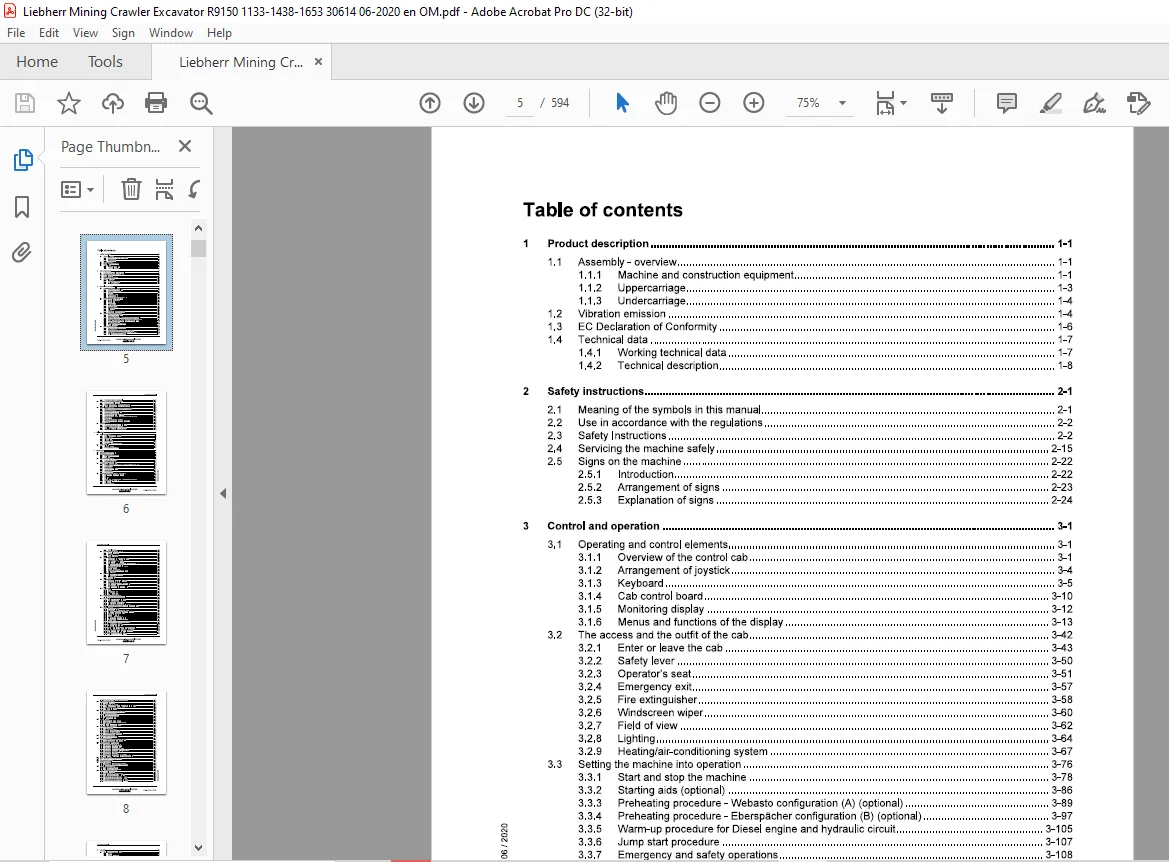
TABLE OF CONTENTS:
Liebherr R 9150 – R 9150B Hydraulic Excavator Operating Manual SN 30614 – PDF DOWNLOAD
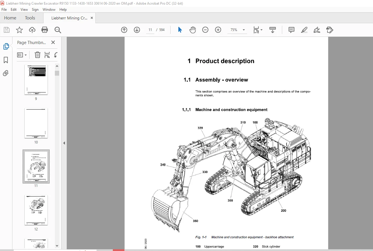
1 Product description 1-1
1 1 Assembly- overview 1-1
1 1 1 Machine and construction equipment 1-1
1 1 2 Uppercarriage 1-3
1 1 3 Undercarriage 1-4
1 2 Vibration emission 1-4
1 3 EC Declaration of Conformity 1-6
1 4 Technical data 1-7
1 4 1 Working technical data 1-7
1 4 2 Technical description 1-8
2 Safety instructions 2-1
2 1 Meaning of the symbols in this manual 2-1
2 2 Use in accordance with the regulations 2-2
2 3 Safety Instructions 2-2
2 4 Servicing the machine safely 2-15
2 5 Signs on the machine 2-22
2 5 1 Introduction 2-22
2 5 2 Arrangement of signs 2-23
2 5 3 Explanation of signs 2-24
3 Control and operation 3-1
3 1 Operating and control elements 3-1
3 1 1 Overview of the control cab 3-1
3 1 2 Arrangement of joystick 3-4
3 1 3 Keyboard 3-5
3 1 4 Cab control board 3-10
3 1 5 Monitoring display 3-12
3 1 6 Menus and functions of the display 3-13
3 2 The access and the outfit of the cab 3-42
3 2 1 Enter or leave the cab 3-43
3 2 2 Safety lever 3-50
3 2 3 Operator’s seat 3-51
3 2 4 Emergency exit 3-57
3 2 5 Fire extinguisher 3-58
3 2 6 Windscreen wiper 3-60
3 2 7 Field of view 3-62
3 2 8 Lighting 3-64
3 2 9 Heating/air-conditioning system 3-67
3 3 Setting the machine into operation 3-76
3 3 1 Start and stop the machine 3-78
3 3 2 Starting aids (optional) 3-86
3 3 3 Preheating procedure – Webasto configuration (A) (optional) 3-89
3 3 4 Preheating procedure – Eberspacher configuration (B) (optional) 3-97
Warm-up procedure for Diesel engine and hydraulic circuit 3-105
N — 3 3 6 Jump start procedure 3-107
0 3 3 7 Emergency and safety operations 3-108
0 3 3 8 Travel movements 3-116
Working with the machine 3-119
3 4 1 Uppercarriage swing movements 3-126
3 4 2 Working position 3-128
3 4 3 Joystick functions when setting up the machine 3-128
3 4 4 Lower the attachment when the engine is not running 3-140
3 4 5 Overload warning device (optional) 3-141
copyright© Liebherr-Mining Equipment Colmar SAS 2020
R 9150- R 9150B / 11212564
MJFCIFSS
Operating Manual
3 4 6 Pressurised attachment (optional) 3-143
3 5 Attaching and dismounting equipment parts 3-144
3 5 1 Use a quick coupler (optional) 3-145
3 5 2 Grapple or shear installed on the stick (optional) 3-147
3 5 3 Hydraulic hammer installed on the stick (optional) 3-151
3 6 General working methods 3-154
3 6 1 Minimum impact working methods for your machine 3-154
3 6 2 Preparatory activities 3-154
3 6 3 Working with the backhoe bucket 3-156
3 6 4 Loading the transport vehicle 3-157
3 6 5 Working with the shovel type bucket 3-158
3 6 6 Working with the clamshell bucket (construction equipment) 3-159
3 6 7 Hoisting work 3-161
3 6 8 Working with the hydraulic hammer 3-162
3 6 9 Working with the grapple (industrial equipment) 3-163
3 6 10 Skimming 3-164
3 7 Transport 3-165
3 7 1 Transporting the machine on a low loader 3-166
3 7 2 Loading the machine with a crane 3-168
3 7 3 Travelling procedures for mining machine 3-169
3 7 4 Excavator lifting and lashing operations 3-172
4 Malfunctions 4-1
4 1 Faults and remedies 4-2
4 1 1 Diesel engine and fuel system 4-2
4 1 2 Hydraulic system 4-9
4 1 3 Transmission 4-9
4 1 4 Electrical system 4-10
4 1 5 Work equipment 4-10
4 1 6 Heating/air-conditioning system 4-10
4 2 Fuses and relays 4-12
4 2 1 Electrical box E50 4-13
4 2 2 Cab connection box E1005 4-15
5 Maintenance 5-1
5 1 Servicing the machine safely 5-1
5 2 Maintenance access doors 5-8
5 2 1 Overview of access doors 5-8
5 2 2 Door lock 5-9
5 3 Maintenance anchor points 5-9
5 3 1 Approved anchor points 5-10
5 3 2 Use the anchor points 5-13
5 4 Lubricants and operating fluids 5-14
5 4 1 General information on changing lubricants and operating fluids 5-14
5 4 2 Lubrication chart 5-15
5 4 3 Lubricant chart 5-17
5 4 4 Operating material chart 5-18
5 4 5 Service station 5-18 ~
5 4 6 Grease devices 5-20 C”II 5 5 Lubricating and operating material specifications 5-21 8–
5 5 1 Lubricating oil for the Diesel engine 5-21 g
5 5 2 Fuel 5-22 :;:::;
5 5 3 Coolant 5-22 ;
5 5 4 Hydraulic oil specifications for LIEBHERR Mining excavators 5-22 c3
5 5 5 Swing and travel gear oils 5-28 ~
5 5 6 Splitterbox oil 5-30
5 5 7 Lubricating grease 5-30
5 5 8 Other lubricants 5-32
5 6 Condition monitoring with oil analysis 5-33
5 6 1 General information 5-33
5 6 2 Oil sampling 5-33
5 6 3 Sample processing 5-41
5 7 Diesel engine 5-45
5 7 1 Check the oil level of the Diesel engine 5-45
5 7 2 Change the Diesel engine oil 5-46
5 7 3 Replace the oil filter elements 5-48
5 7 4 Replace the filter element of the oil separator (if installed) 5-49
5 7 5 Belts and tensioning devices 5-49
5 7 6 Check and adjust the valve clearance 5-50
5 7 7 Vibration damper 5-50
5 7 8 Heater flange (optional) 5-50
5 7 9 Mounting screws of the Diesel engine 5-50
5 7 10 Elastic bedding 5-51
5 8 Splitterbox 5-52
5 8 1 Splitterbox mounting screws 5-52
5 8 2 Elastic bedding 5-54
5 8 3 Breather filter 5-55
5 9 Cooling system 5-55
5 9 1 Check and clean the cooling system 5-55
5 9 2 Check the coolant level 5-56
5 9 3 Coolant antifreeze and anti-corrosion fluid 5-57
5 9 4 Change the coolant 5-57
5 9 5 Replace the coolant filter (if installed) 5-59
5 10 Fuel system 5-60
5 10 1 Refuel 5-60
5 10 2 Drain the fuel tank 5-63
5 10 3 Clean the fuel tank 5-64
5 10 4 Fuel filtering system 5-65
5 11 Compressed air system (optional) 5-76
5 11 1 Pressurised attachment (optional) 5-76
5 12 Dry air filter 5-78
5 12 1 Replace the primary filter element 5-81
5 12 2 Replace the safety element 5-82
5 12 3 Clean the precleaner air channels 5-83
5 12 4 Clean the housing of the air filter elements 5-84
5 12 5 Check the air intake system, hoses, elbow tubes, clamps 5-85
5 13 Hydraulic system 5-85
5 13 1 Preparatory activities 5-86
5 13 2 Check the oil level in the hydraulic tank 5-86
5 13 3 Release the pressure from the hydraulic system 5-87
5 13 4 Drain and fill the hydraulic tank 5-89
5 13 5 Hydraulic oil coolers 5-91
5 13 6 Leak oil filter and return filter 5-91
5 13 7 Piloting and replenishing oil filters 5-92
5 13 8 High pressure filters in working circuit 5-94
5 13 9 Servo oil circuit 5-97
5 13 10 Remove the intake hoses from the pumps 5-98
5 13 11 Bleed the hydraulic pumps 5-99
5 13 12 Bleed the hydraulic cylinders 5-101
5 13 13 Bleed the valve blocks 5-101
5 13 14 Return-line filter for the hydraulic hammer (optional) 5-102
5 13 15 Oil cooler protection filters (optional equipment) 5-104
5 13 16 Auxiliary hydraulic outlet (optional equipment) 5-105
5 13 17 Servicing the hydraulic cylinder 5-107
5 13 18 Replacement of the hydraulic hoses 5-108
copyright© Liebherr-Mining Equipment Colmar SAS 2020
R 9150- R 9150B / 11212564
MJFCIFSS
Operating Manual
5 13 19 Progressive criss-cross tightening procedure 5-112
5 14 Oil changes on components 5-113
5 14 1 General information 5-113
5 14 2 Swing gear- Oil change 5-113
5 14 3 Travel gear and Lifetime travel gear (optional) – Oil change 5-116
5 14 4 Swing gears and travel gears flushing 5-121
5 14 5 Splitterbox – Oil change 5-121
5 15 Track components 5-123
5 15 1 Check the track components mounting 5-123
5 15 2 Check the track tension 5-128
5 15 3 Increase the track tension 5-128
5 15 4 Decrease the track tension 5-129
5 15 5 Clean the travel gear 5-130
5 16 Electrical system 5-131
5 16 1 Notes on the electrical system 5-131
5 16 2 Batteries switches and EDC connectors 5-131
5 16 3 Battery care 5-133
5 16 4 Electrical components location 5-135
5 17 Heating/air-conditioning system 5-136
5 17 1 Heating system 5-137
5 17 2 Air-conditioning system 5-139
5 17 3 Additional maintenance work 5-142
5 17 4 Additional cab heater (optional) 5-143
5 17 5 Cab preheating system (optional) 5-143
5 18 Cab pressurization (optional) 5-143
5 18 1 Aeration device (optional) 5-143
5 19 Greasing the machine 5-144
5 19 1 Lubrication of attachment bearing points 5-144
5 19 2 Lubrication of special tools (optional) 5-145
5 20 Check mounting bolts for tightness 5-145
5 20 1 Counterweight mounting bolts 5-146
5 20 2 Mounting bolts of the swing ring 5-147
5 20 3 Mounting bolts of the fuel tank 5-147
5 20 4 Mounting bolts of the hydraulic tank 5-148
5 20 5 Mounting bolts of swing gear and swing motor 5-149
5 20 6 Mounting bolts of hydraulic pumps 5-150
5 20 7 Mounting bolts of the cab 5-150
5 20 8 Mounting bolts of the cab elevation (if installed) 5-152
5 20 9 Mounting bolts of removable side frames (if installed) 5-153
5 21 Quick coupler ( optional) 5-153
5 22 Drive unit brakes and swing gear brakes 5-153
5 23 Fire suppression system 5-154
5 24 Starting aids (optional) 5-154
5 24 1 Starting aids – Webasto configuration (A) 5-154
5 24 2 Starting aids – Eberspacher configuration (8) 5-158
5 25 General maintenance points 5-161
5 25 1 Replacing working parts 5-161
5 25 2 Welding work on the machine 5-162
5 26 Control and maintenance chart 5-162 ~
5 26 1 General information 5-163 ~
5 26 2 How to use the maintenance chart 5-163 8
5 26 3 Daily Maintenance Schedule – R9150 5-165 g
5 26 4 250 Hours Maintenance Schedule – R9150 5-171 :e
5 26 5 500 Hours Maintenance Schedule – R9150 5-173 ~ i;:
5 26 6 1000 Hours Maintenance Schedule – R9150 5-180 c3
5 26 7 2000 Hours Maintenance Schedule – R9150 5-188 ~
6 Appendix 6-1
6 1 Visual check of the hydraulic hoses 6-1
6 1 1 Preface 6-1
6 1 2 General information 6-2
6 1 3 Components functions 6-4
6 1 4 Recommendations for hose assembly maintenance 6-5
6 2 Cleaning procedure for hydraulic circuits 6-9
6 2 1 Preface 6-9
6 2 2 General information about hydraulic oil contamination 6-9
6 2 3 General cleaning procedure 6-11
6 2 4 Location of the hydraulic tank filters 6-11
6 2 5 Working pumps circuit 6-12
6 2 6 Swing circuit 6-18
6 2 7 Cooling pumps circuit 6-21
6 2 8 Travel motors circuit 6-25
6 2 9 Backhoe cylinders lines 6-28
6 2 10 Shovel cylinders lines 6-34
6 2 11 Clean the hydraulic tank 6-43
6 2 12 Restart the machine 6-43
6 2 13 Monitor the restarted machine 6-45
6 3 Centralized lubrication system 6-45
Need help? Contact: [email protected]
https://vimeo.com/890292362?share=copy
S.V