Liebherr R 9250 1357 Hydraulic Excavator Operating Manual SN 30616 – PDF DOWNLOAD
Original price was: $85.95.$29.95Current price is: $29.95.
Liebherr R 9250 1357 Hydraulic Excavator Operating Manual SN 30616 – PDF DOWNLOAD
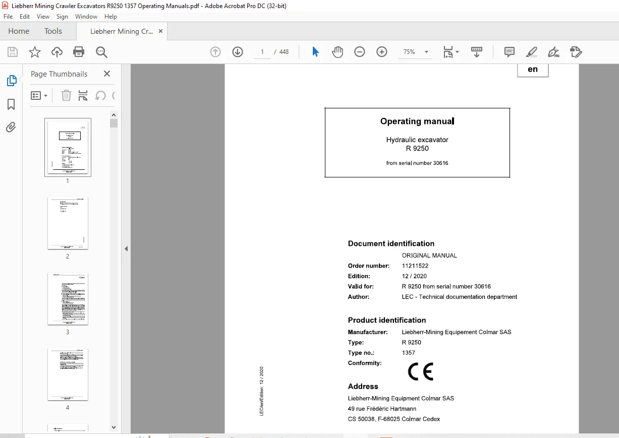
Product identification
Manufacturer: Liebherr-Mining Equipement Colmar SAS
Type: R 9250
Type no.: 1357
Description
Liebherr R 9250 1357 Hydraulic Excavator Operating Manual SN 30616 – PDF DOWNLOAD
FILE DETAILS:
Liebherr R 9250 1357 Hydraulic Excavator Operating Manual SN 30616 – PDF DOWNLOAD
Language : English
Pages : 448
Downloadable : Yes
File Type : PDF
Size: 95 MB
DESCRIPTION:
Liebherr R 9250 1357 Hydraulic Excavator Operating Manual SN 30616 – PDF DOWNLOAD
Product identification
Manufacturer: Liebherr-Mining Equipement Colmar SAS
Type: R 9250
Type no.: 1357
Preface:
These operating instructions have been written for the machine operator and for the maintenance personnel of the machine.
They contain:
The operating instructions are to be read and used carefully by all persons who carry out work with or on the machine before putting the machine into service for the first time and later, at regular intervals.
Work with or on the machine includes, for example:
- Operation including setting up and equipping, rectifying malfunctions during the course of work, resolving production dropouts, care, disposal of operating and process materials.
- Maintenance, including maintenance, inspection and repair work.
- Transportation or loading the machine.
The operating instructions allow the machine operator to familiarize themselves with the machine more easily and prevent malfunctions occurring due to improper operation. The observance of the operating and maintenance instructions by maintenance personnel:
- Increases reliability in use.
- Extends the service life of your machine.
- Reduces repair costs and downtime.
The operating instructions belong with the machine for the entire lifetime of the machine. Place a copy in an easily reached position on the cab storage shelf. This copy must be replaced immediately if lost, damaged or unreadable.
The operating and maintenance instructions must be completed by information on current national regulations for accident prevention and protection. In addition to the operating instructions and legally binding regulations on accident prevention which apply in the user country and at point of use, authorized specialist rules for safe and correct working procedures are also to be observed.
These operating and maintenance instructions contain all the information required for operating and maintaining your machine.
- Some illustrations in these operating instructions may depict details and working devices which differ from your machine.
- In some illustrations, protective devices and covers have been removed in the interests of better presentation.
- Improvements, which are always being incorporated into our machines, may result in changes to your machine which are not yet indicated in these operating instructions.
IMAGES PREVIEW OF THE MANUAL:
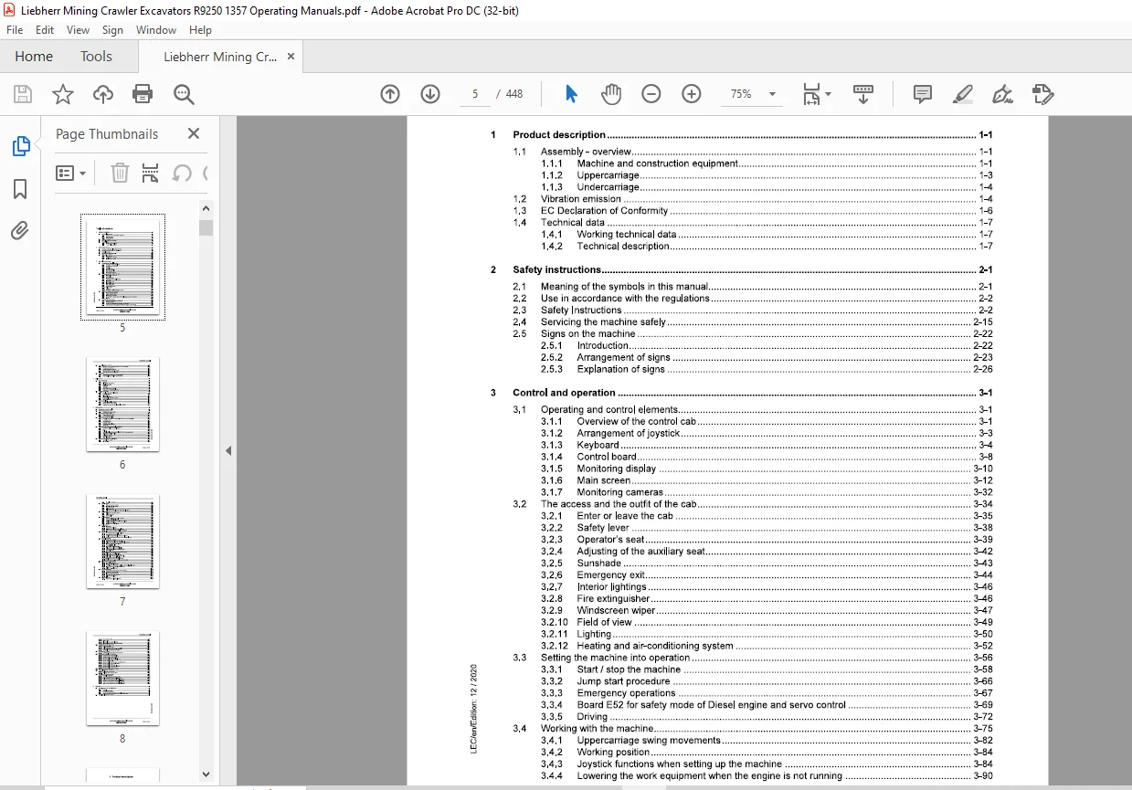
TABLE OF CONTENTS:
Liebherr R 9250 1357 Hydraulic Excavator Operating Manual SN 30616 – PDF DOWNLOAD
1 Product description 1-1
1 1 Assembly- overview 1-1
1 1 1 Machine and construction equipment 1-1
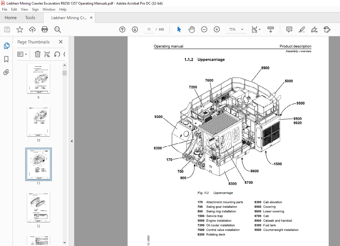
1 1 2 Uppercarriage 1-3
1 1 3 Undercarriage 1-4
1 2 Vibration emission 1-4
1 3 EC Declaration of Conformity 1-6
1 4 Technical data 1-7
1 4 1 Working technical data 1-7
1 4 2 Technical description 1-7
2 Safety instructions 2-1
2 1 Meaning of the symbols in this manual 2-1
2 2 Use in accordance with the regulations 2-2
2 3 Safety Instructions 2-2
2 4 Servicing the machine safely 2-15
2 5 Signs on the machine 2-22
2 5 1 Introduction 2-22
2 5 2 Arrangement of signs 2-23
2 5 3 Explanation of signs 2-26
3 Control and operation 3-1
3 1 Operating and control elements 3-1
3 1 1 Overview of the control cab 3-1
3 1 2 Arrangement of joystick 3-3
3 1 3 Keyboard 3-4
3 1 4 Control board 3-8
3 1 5 Monitoring display 3-10
3 1 6 Main screen 3-12
3 1 7 Monitoring cameras 3-32
3 2 The access and the outfit of the cab 3-34
3 2 1 Enter or leave the cab 3-35
3 2 2 Safety lever 3-38
3 2 3 Operator’s seat 3-39
3 2 4 Adjusting of the auxiliary seat 3-42
3 2 5 Sunshade 3-43
3 2 6 Emergency exit 3-44
3 2 7 Interior lightings 3-46
3 2 8 Fire extinguisher 3-46
3 2 9 Windscreen wiper 3-47
3 2 10 Field of view 3-49
3 2 11 Lighting 3-50
3 2 12 Heating and air-conditioning system 3-52
3 3 Setting the machine into operation 3-56
3 3 1 Start I stop the machine 3-58
3 3 2 Jump start procedure 3-66
3 3 3 Emergency operations 3-67
3 3 4 Board E52 for safety mode of Diesel engine and servo control 3-69
3 3 5 Driving 3-72
Working with the machine 3-75
3 4 1 Uppercarriage swing movements 3-82
3 4 2 Working position 3-84
3 4 3 Joystick functions when setting up the machine 3-84
3 4 4 Lowering the work equipment when the engine is not running 3-90
3 5 General working methods 3-90
3 5 1 Minimum impact working methods for your machine 3-90
3 5 2 Preparatory activities 3-91
3 5 3 Positioning of the machine 3-92
3 5 4 Working with the backhoe bucket 3-93
3 5 5 Working with the Shovel bucket 3-95
3 6 Transport 3-98
3 6 1 Travelling procedures for mining machine 3-98
3 6 2 Excavator lifting and lashing operations 3-101
4 Malfunctions 4-1
4 1 Error code charts 4-2
4 1 1 Sensors 4-2
4 1 2 Electronic components 4-4
4 1 3 Regulating circuit 4-5
4 1 4 CAN BUS 4-5
4 1 5 Joysticks 4-6
4 1 6 Error with warning symbols 4-6
4 1 7 Heating/ air conditioning system 4-8
4 2 Faults and remedies 4-9
4 2 1 Diesel engine and fuel system 4-9
4 2 2 Hydraulic system 4-10
4 2 3 Transmission 4-10
4 2 4 Electrical system 4-11
4 2 5 Heating/air-conditioning system 4-11
4 2 6 Work equipment 4-11
4 3 Fuses and relays 4-12
4 3 1 Power electrical box E1003 4-12
4 3 2 Cab connection box E1005 4-14
4 3 3 Heating/ air conditioning electrical box E1006 4-16
5 Maintenance 5-1
5 1 Servicing the machine safely 5-1
5 2 Maintenance access doors 5-7
5 2 1 Overview of access doors 5-7
5 3 Maintenance anchor points 5-13
5 3 1 Approved anchor points 5-14
5 3 2 Use the anchor points 5-17
5 4 Lubricants and operating fluids 5-18
5 4 1 General information on changing lubricants and operating fluids 5-18
5 4 2 Lubrication chart 5-19
5 4 3 The service trap 5-20
5 4 4 Lubricant chart 5-22
5 4 5 Operating material chart 5-24
5 4 6 Service trap 5-24
5 5 Lubricating and operating material specifications 5-26
5 5 1 Lubricating oil for the Diesel engine 5-26
5 5 2 Fuel 5-26 ~
5 5 3 Coolant 5-26 C”II 5 5 4 Hydraulic oil specifications for LIEBHERR Mining excavators 5-27 -~-
5 5 5 Swing and travel gear oils 5-32 g
5 5 6 Splitterbox oil 5-34 :;:::;
5 5 7 Lubricating grease 5-35 ;
5 5 8 Other lubricants 5-37 c3
5 6 Condition monitoring with oil analysis 5-37 ~
5 6 1 General information 5-37
5 6 2 Oil sampling 5-38
5 6 3 Sample processing 5-44
5 7 Diesel engine 5-48
5 7 1 Check of engine oil level 5-48
5 7 2 Diesel engine oil change 5-49
5 7 3 Mounting screws 5-51
5 7 4 Elastic bedding 5-52
5 7 5 Belt for the 24 V alternator of the Diesel engine 5-53
5 8 Splitterbox 5-53
5 8 1 Splitterbox mounting screws 5-53
5 8 2 Elastic bedding 5-55
5 8 3 Breather filter 5-56
5 9 Cooling system 5-56
5 9 1 Check and clean the cooling system 5-56
5 9 2 Check the coolant level 5-58
5 9 3 Coolant antifreeze and anti-corrosion fluid 5-59
5 9 4 Change the coolant 5-59
5 9 5 Replace the coolant filters 5-60
5 10 Fuel system 5-62
5 10 1 Refuelling 5-62
5 10 2 Draining the fuel tank 5-64
5 10 3 Emptying and cleaning the fuel tank 5-66
5 10 4 Draining and changing fuel filter cartridges 5-67
5 11 Dry air filter 5-68
5 11 1 To change the primary filter element 5-69
5 11 2 Changing the safety element 5-70
5 11 3 To clean the air channels for the precleaner 5-71
5 11 4 Check the air intake system, hoses, elbows, clamps 5-71
5 12 Hydraulic system 5-72
5 12 1 Preparatory activities 5-72
5 12 2 Check the oil level in the hydraulic tank 5-73
5 12 3 Release the pressure from the hydraulic system 5-73
5 12 4 Drain and fill the hydraulic tank 5-74
5 12 5 Hydraulic oil coolers 5-75
5 12 6 Return, leak oil and air filters 5-76
5 12 7 Piloting and replenishing oil filters 5-77
5 12 8 High pressure filters in working circuit 5-79
5 12 9 Servo oil circuit 5-80
5 12 10 Remove the intake hoses from the pumps 5-82
5 12 11 Bleeding of hydraulic pumps 5-83
5 12 12 Bleeding the hydraulic cylinders 5-85
5 12 13 Oil cooler protection filters (optional) 5-86
5 12 14 Servicing the hydraulic cylinder 5-87
5 12 15 Replacement of the hydraulic hoses 5-88
5 12 16 Progressive criss-cross tightening procedure 5-91
5 13 Oil changes on components 5-92
5 13 1 General information 5-92
5 13 2 Swing gear – Oil change 5-93
5 13 3 Travel gear and Lifetime travel gear (optional) – Oil change 5-95
5 13 4 Swing gears and travel gears flushing 5-99
5 13 5 Splitterbox – oil change 5-100
5 14 Track components 5-102
5 14 1 Checking the track components mounting 5-102
14 2 Check the track tension 5-105
5 14 3 Increase the track tension 5-105
5 14 4 Decrease the track tension 5-106
I 5 14 5 Clean the travel gear 5-107
5 15 Electrical system 5-108
5 15 1 Notes on the electrical system 5-108
5 15 2 Main battery switch 5-108
5 15 3 Battery care 5-109
5 15 4 Electrical components location 5-110
5 15 5 Electrical boxes and cab pressurization 5-111
5 16 Heating/air conditioning system 5-111
5 16 1 Heating system 5-113
5 16 2 Air-conditioning system 5-114
5 16 3 Dual air-conditioning system (optional) 5-117
5 16 4 Additional maintenance operations 5-117
5 17 Greasing the machine 5-118
5 17 1 Lubrication of attachment bearing points 5-118
5 18 Check mounting bolts for tightness 5-119
5 18 1 Counterweight mounting bolts 5-120
5 18 2 Threaded studs of the swing ring 5-121
5 18 3 Mounting bolts of the fuel tank 5-122
5 18 4 Mounting bolts of the hydraulic tank 5-123
5 18 5 Frame mounting bolts 5-124
5 18 6 Mounting bolts of swing gear and swing motor 5-124
5 18 7 Mounting bolts of hydraulic pumps 5-125
5 18 8 Mounting bolts of the cab 5-126
5 18 9 Mounting bolts of the cab elevation 5-127
5 18 10 Mounting bolts of side frames 5-127
5 19 Drive unit brakes and swing gear brakes 5-128
5 20 General maintenance points 5-128
5 20 1 Replacing working parts 5-128
5 20 2 Welding work on the machine 5-128
5 21 Control and maintenance chart 5-129
5 21 1 General information 5-129
5 21 2 How to use the maintenance chart 5-130
5 21 3 Daily Maintenance Schedule – R9250 5-132
5 21 4 250 Hours Maintenance Schedule – R9250 5-138
5 21 5 500 Hours Maintenance Schedule – R9250 5-144
5 21 6 1000 Hours Maintenance Schedule – R9250 5-151
5 21 7 2000 Hours Maintenance Schedule – R9250 5-159
6 Appendix 6-1
6 1 Visual check of the hydraulic hoses 6-1
6 1 1 Preface 6-1
6 1 2 General information 6-2
6 1 3 Components functions 6-4
6 1 4 Recommendations for hose assembly maintenance 6-5
6 2 Centralized lubrication system 6-9
Contact us: [email protected]
https://vimeo.com/825100937?share=copy
PLEASE NOTE:
- This is the SAME manual used by the dealers to troubleshoot any faults in your vehicle. This can be yours in 2 minutes after the payment is made.
- Contact us at [email protected] should you have any queries before your purchase or that you need any other service / repair / parts operators manual.
S.V