Liebherr R954C-Demolition 780 784 785 976 1090 1120 1175 1328 1381 1390 Hydraulic Excavator Operator’s Manual SN 30979
$29.95
Liebherr R954C-Demolition 780 784 785 976 1090 1120 1175 1328 1381 1390 Hydraulic Excavator Operator’s Manual SN 30979 – PDF DOWNLOAD
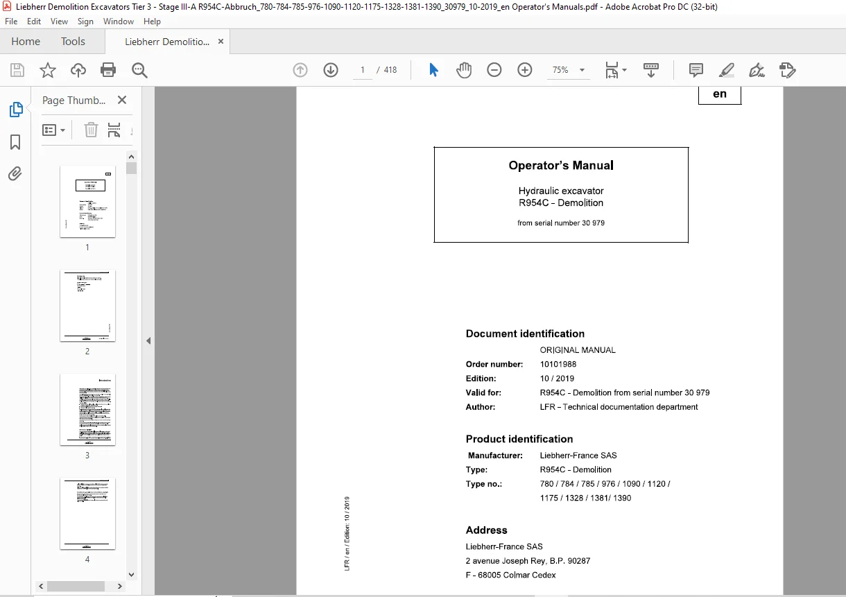
Product identification
Manufacturer: Liebherr-France SAS
Type: R954C – Demolition
Type no.: 780 / 784 / 785 / 976 / 1090 / 1120 / 1175 / 1328 / 1381/ 1390
Description
Liebherr R954C-Demolition 780 784 785 976 1090 1120 1175 1328 1381 1390 Hydraulic Excavator Operator’s Manual SN 30979 – PDF DOWNLOAD
FILE DETAILS:
Liebherr R954C-Demolition 780 784 785 976 1090 1120 1175 1328 1381 1390 Hydraulic Excavator Operator’s Manual SN 30979 – PDF DOWNLOAD
Language : English
Pages : 418
Downloadable : Yes
File Type : PDF
IMAGES PREVIEW OF THE MANUAL:
DESCRIPTION:
Liebherr R954C-Demolition 780 784 785 976 1090 1120 1175 1328 1381 1390 Hydraulic Excavator Operator’s Manual SN 30979 – PDF DOWNLOAD
Product identification
Manufacturer: Liebherr-France SAS
Type: R954C – Demolition
Type no.: 780 / 784 / 785 / 976 / 1090 / 1120 / 1175 / 1328 / 1381/ 1390
Introduction:
- This operating manual has been specifically devised for machine operators and maintenance personnel. It contains important warnings, information and tips regarding the maintenance and proper operation of the machine. It assists you in becoming familiar with the functions and features of the machine and helps prevent incorrect operation.
- By strictly adhering to the instructions in the operating manual, you can significantly enhance the reliability and service life of the machine.
- The operating manual is an integral part of the scope of delivery of the machine. Ensure that a copy is at all times available in the storage compartment in the operator’s cab.
- Carefully read the operating manual before starting the machine and then regularly read it again. All persons carrying out work on or with the machine must be fully familiar with the content of the operating manual and must adhere to the instructions.
– Maintenance including inspection, servicing and repair.
– Transport or loading of the machine.
- The machine owner must ensure that this operating manual is complemented with the relevant statutory regulations for accident prevention and the protection of the environment. Apart from the instructions in this operating manual and the statutory accident prevention, health and safety regulations applicable in the country of operation, all personnel working on or with the machine must adhere to best practice for safe and proper operation.
- Certain sections in this manual might not apply to your specific model.
- Some of the figures in this operating manual might show details or equipment that differ from those in your machine.
- Some of the figures show the equipment with guards or covers removed (for better depiction).
- As our products are constantly being improved, certain changes might be made to the equipment which are not referred to specifically in this operating manual.
- Should you require additional information or if you have any queries, please contact the LIEBHERR customer service department.
Warranty and liability:
- Due to the range of products (e.g. fuels, lubricants, tool attachments, spare parts) available from other manufacturers, LIEBHERR is not in a position to assess the compatibility of these products with its own machines. This also applies in relation to possible effects that third-party products have on LIEBHERR products and vice versa.
- It is therefore the responsibility of the machine owner to assess whether third-party products can be safely used in conjunction with the LIEBHERR machine. LIEBHERR shall not be liable for damage to or downtimes of LIEBHERR machine caused by the use a third-party products. Such damage is not covered by the LIEBHERR warranty.
- LIEBHERR shall not be liable for damage caused by improper operation, insufficient maintenance or non-compliance with safety instructions.
Amendments, general terms and conditions, copyright:
- We reserve the right to modify our products and amend the instructions in this operating manual without prior notice.
- The reproduction or publication of the content of this operating manual (including figures) is prohibited. LIEBHERR reserves all rights in this operating manual, including copyright.
- The warranty and liability clauses of the general business terms and conditions of LIEBHERR apply.
TABLE OF CONTENTS:
Liebherr R954C-Demolition 780 784 785 976 1090 1120 1175 1328 1381 1390 Hydraulic Excavator Operator’s Manual SN 30979 – PDF DOWNLOAD
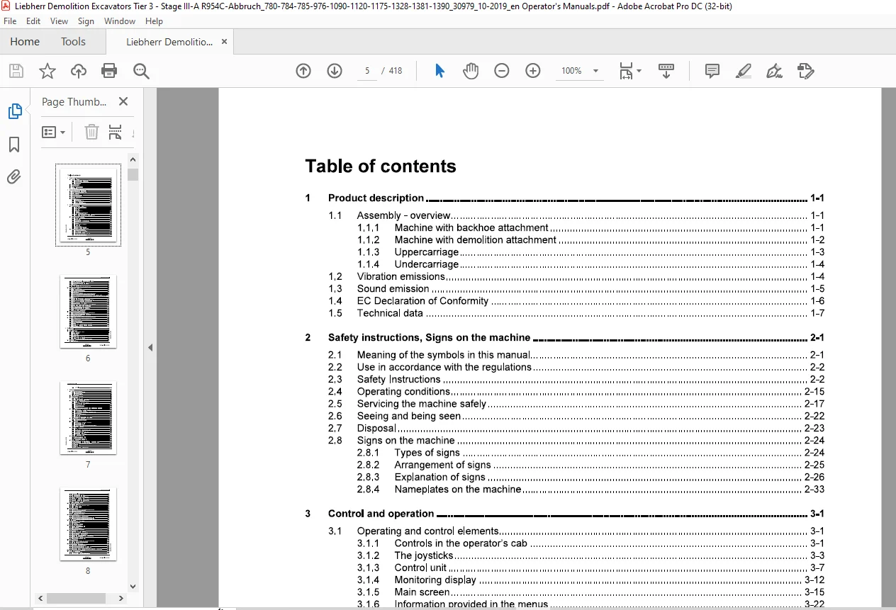
1 Product description 1-1
1 1 Assembly- overview 1-1
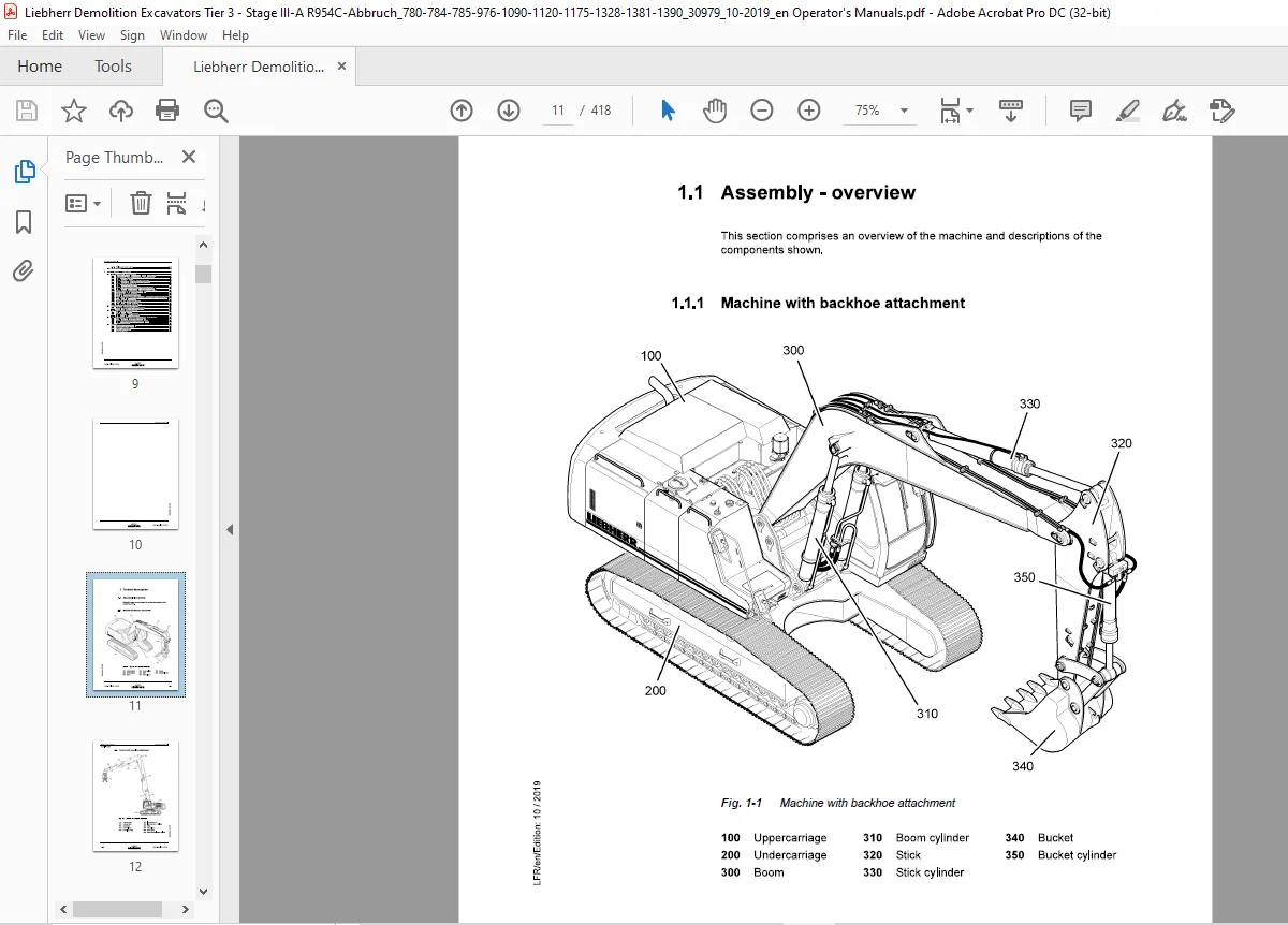
1 1 1 Machine with backhoe attachment 1-1
1 1 2 Machine with demolition attachment 1-2
1 1 3 Uppercarriage 1-3
1 1 4 Undercarriage 1-4
1 2 Vibration emissions 1-4
1 3 Sound emission 1-5
1 4 EC Declaration of Conformity 1-6
1 5 Technical data 1-7
2 Safety instructions, Signs on the machine 2-1
2 1 Meaning of the symbols in this manual 2-1
2 2 Use in accordance with the regulations 2-2
2 3 Safety Instructions 2-2
2 4 Operating conditions 2-15
2 5 Servicing the machine safely 2-17
2 6 Seeing and being seen 2-22
2 7 Disposal 2-23
2 8 Signs on the machine 2-24
2 8 1 Types of signs 2-24
2 8 2 Arrangement of signs 2-25
2 8 3 Explanation of signs 2-26
2 8 4 Nameplates on the machine 2-33
3 Control and operation 3-1
3 1 Operating and control elements 3-1
3 1 1 Controls in the operator’s cab 3-1
3 1 2 The joysticks 3-3
3 1 3 Control unit 3-7
3 1 4 Monitoring display 3-12
3 1 5 Main screen 3-15
3 1 6 Information provided in the menus 3-22
3 1 7 Controls on side control desks 3-36
3 1 8 Controls and instrumentation for optional equipment 3-38
3 1 9 Display for LIEBHERR particle filter (option) 3-42
3 2 Access and equipment of the cab 3-44
3 2 1 Entering or leaving the cab 3-44
3 2 2 Safety lever 3-46
3 2 3 Operator seat 3-47
3 2 4 Putting on and releasing the safety belt 3-50
3 2 5 Windscreen 3-51
3 2 6 Sunshade 3-51
3 2 7 Emergency exit – rear window 3-52
3 2 8 Interior lights 3-52
3 2 9 Fire extinguisher 3-53
3 2 10 The heater and air conditioner 3-53
Setting the machine into operation 3-64
3 3 1 Before starting the machine 3-64
3 3 2 Turning on the electrical system 3-65
3 3 3 Starting the Diesel engine 3-66
3 3 4 Speed adjustment and operating modes 3-67
3 3 5 Notes after starting the engine 3-69
copyright by
R954C – Demolition/ 10101988
MJFCIFSS
Operator’s Manual
3 3 6 Warm-up phase for Diesel engine and hydraulic circuit 3-69
3 3 7 Switching the Diesel engine off 3-70
3 3 8 Automatic motorstop after low idle (option) 3-72
3 3 9 Starting aids 3-72
3 3 10 Jump start procedure 3-74
3 3 11 Immobilizer with electronic ignition key (option) 3-74
3 4 Working with the machine 3-77
3 4 1 The travel movements 3-77
3 4 2 Travel warning device (option) 3-81
3 4 3 Uppercarriage swing movements 3-82
3 4 4 Working position 3-85
3 4 5 Working attachment control 3-85
3 4 6 Lowering the working attachment with the engine shut down 3-87
3 4 7 Description of the reach monitoring system Liebherr Demolition Control (LDC) 3-88
3 4 8 Determining the Excavator Configuration Number (ECN) of the reach monitoring system
LDC 3-89
3 4 9 Setting the ECN 3-98
3 4 10 Control of a long-reach demolition attachment 3-100
3 4 11 Demolition work with the reach monitoring system LDC 3-103
3 4 12 Rotating, tilting, locking and unlocking a working tool 3-108
3 4 13 Control of the hammer or the shears 3-110
3 4 14 AHS11 proportional control (option) 3-112
3 4 15 Commutation of control for an additional attachment (option) 3-112
3 4 16 Special control system of the joysticks (Option) 3-115
3 4 17 Switching to the special control system (option) 3-117
3 4 18 Cut-off of attachment movements (option) 3-119
3 4 19 Use of the excavator for lifting loads overhead 3-122
3 4 20 Overload warning system (option) 3-123
3 4 21 Adjustable hydraulic cab (option) 3-124
3 5 Operating the excavator in safety modes 3-127
3 5 1 Board E52 for safety mode of Diesel engine & servo control 3-127
3 5 2 Safety operation of the main working pumps 3-129
3 5 3 Emergency operation of boom cylinders (option) 3-130
3 6 Recovering, towing the machine 3-132
3 6 1 Towing with the machine, emergency towing of the machine 3-132
3 7 Working methods 3-135
3 7 1 Minimum impact working methods for your machine 3-135
3 7 2 Preparatory activities 3-136
3 7 3 Using a backhoe bucket 3-137
3 7 4 Loading a transport vehicle 3-138
3 7 5 Skimming 3-139
3 7 6 Using a clamshell bucket (earthmoving attachment) 3-140
3 7 7 Using a multiple tine grapple (industrial attachment) 3-142
3 7 8 Using an hydraulic hammer 3-143
4 Troubleshooting 4-1
4 1 Error code list 4-2
4 2 Faults and remedies 4-8 m
4 2 1 Diesel engine and fuel system 4-8 o
C’II 4 2 2 Hydraulic system 4-9 ;;
4 2 3 Transmission 4-10
i::::
4 2 4 Electrical system 4-11 °
4 2 5 Work equipment 4-11 I
4 2 6 Heating/air-conditioning system 4-12 ~
4 2 7 LIEBHERR particles filter system 4-13 LL
I 4 2 8 Errors of LIEBHERR reach monitoring system LDC 4-14
4 3 Fuses and relays 4-18
4 3 1 Fuse box E50 4-18
copyright by
R954C – Demolition / 10101988
MJFCIFSS
Operator’s Manual
4 3 2 A1010 Plate 4-19
5 Maintenance 5-1
5 1 Maintenance access doors 5-1
5 1 1 Overview of access doors 5-1
5 1 2 Door retaining rods 5-2
5 1 3 Engine hood retainer 5-3
5 2 Cleaning machine 5-3
5 3 Care for rubber components 5-4
5 4 Lubricants and fluids 5-4
5 4 1 General information 5-4
5 4 2 Filling quantities and lubricating chart 5-5
5 5 Lubricants and fluids specification 5-7
5 5 1 Dieselfuels 5-7
5 5 2 Lubricating oil for the diesel engine 5-8
5 5 3 Coolants for diesel engine 5-10
5 5 4 Hydraulic oil 5-12
5 5 5 Lubricants for gearboxes 5-18
5 5 6 Grease 5-20
5 5 7 Lubricants and care products for electrical and mechanical components 5-20
5 6 Diesel engine 5-21
5 6 1 Checking the oil level in the diesel engine 5-21
5 6 2 Changing the diesel engine oil 5-22
5 6 3 Belt for the A/C compressor and alternator installation 5-23
5 6 4 Vibration damper 5-24
5 6 5 Checking mounting screws 5-24
5 6 6 Oil separator 5-25
5 6 7 Heater flange 5-26
5 6 8 Checking and adjustment of valve clearance 5-26
5 7 LIEBHERR particles filter (option) 5-29
5 7 1 Drain the condensation water 5-29
5 7 2 Water separator maintenance 5-29
5 8 Cooling system 5-30
5 8 1 Checking and cleaning the cooling system 5-30
5 8 2 Checking the coolant level 5-31
5 8 3 Changing the coolant 5-31
5 8 4 Check of the coolant and adjustment of the mixing ratio 5-33
5 8 5 Reversible fan (option) 5-37
5 9 Fuel system 5-38
5 9 1 Refuelling 5-38
5 9 2 Electrical refuelling pump (optional extra) 5-39
5 9 3 Draining the fuel tank 5-42
5 9 4 Emptying and cleaning the fuel tank 5-43
5 9 5 Draining the fuel prefilter 5-43
5 9 6 Changing fuel filter cartridges 5-44
5 9 7 Bleeding the fuel system 5-46
5 10 Dry air filter 5-49
0) 5 10 1 Changing the main element 5-50
5 10 2 Changing the safety element 5-51
5 10 3 Monitoring the filtered air line 5-52
Hydraulic system 5-52
5 11 1 Depressurizing the hydraulic system 5-52
5 11 2 Checking the oil level, emptying and refilling the hydraulic tank 5-53
5 11 3 Checking and cleaning the oil cooler system 5-56
5 11 4 Return filter 5-56
I 5 11 5 Leak oil filter 5-58
5 11 6 Servofilter 5-59
5 11 7 Replenishing oil filter in swing circuit 5-59
5 11 8 Servo control circuit 5-60
5 11 9 Bleeding the hydraulic pumps 5-61
5 11 10 Bleeding the hydraulic cylinders 5-62
5 11 11 Removing the suction hose to the pumps 5-64
5 11 12 Vent filter on the hydraulic tank 5-65
5 11 13 Bypass oil filter for hydraulic system ( option) 5-65
5 11 14 Return oil filter for hydraulic hammer (option) 5-67
5 11 15 Servicing the hydraulic cylinder 5-68
5 11 16 Replacing hydraulic hoses 5-69
Oil changes on components 5-70
5 12 1 General information 5-70
5 12 2 Swing gear – Oil level check and oil change 5-71
5 12 3 Travel gear oil change 5-71
5 12 4 Splitterbox – Oil change 5-73
The track components 5-73
5 13 1 Checking the mounting screws of the track components 5-74
5 13 2 Checking the track chains tension 5-7 4
5 13 3 Retensioning the track 5-75
5 13 4 Releasing the track chain tension 5-76
5 13 5 Cleaning the track components 5-77
Hydraulic undercarriage 5-78
5 14 1 Retracting and extending the track frames 5-78
5 14 2 Lubricating the hydraulic undercarriage 5-80
5 14 3 Checking the track gauge of the track frames (CVC-1 only) 5-82
5 14 4 Checking the track gauge of the track frames (CVC-2 only) 5-83
Electrical system 5-86
5 15 1 Notes on the electrical system 5-86
5 15 2 Main battery switch 5-86
5 15 3 Battery care 5-87
5 15 4 Slip ring assembly (option) 5-88
Heating/air-conditioning system 5-88
5 16 1 Recirculated and fresh air filters 5-88
5 16 2 Heating system 5-89
5 16 3 Air-conditioning system 5-90
5 16 4 Cab pressuring system (option) 5-92
Greasing the machine 5-93
5 17 1 The centralized lubrication system 5-93
5 17 2 Semi automatic and full automatic systems 5-95
5 17 3 Operation of the semi automatic system 5-95
5 17 4 Operation of the full automatic system 5-96
5 17 5 Emergency lubrication with defective lubrication system 5-98
5 17 6 To refill a grease container 5-98
5 17 7 Changes in the lubrication circuit 5-99
5 17 8 Greasing the grab (optional extra) 5-100
Quick-change systems 5-101
5 18 1 Greasing the mechanical quick-change adapter (option) 5-101
5 18 2 Hydraulic quick-change adapter (option) 5-101
5 18 3 LIKUFIX (option) 5-102
Check mounting bolts for tightness 5-103 m 0
5 19 1 Mounting bolts of the counterweight 5-104 ~
5 19 2 Mounting screws of the swing ring 5-104 ~
5 19 3 Mounting screws of the hydraulic oil and fuel tank 5-105 g
5 19 4 Mounting screws of the swing gear and motor 5-105 ~
5 19 5 Mounting bolts central piece to side frames (option “removable side frames”) 5-105 ~
Drive unit brakes and swing gear brakes 5-106 ~
General maintenance points 5-106 ~
5 21 1 Replacing working parts 5-106
5 21 2 Checking or replacing the teeth on the bucket 5-107
5 21 3 Welding work on the machine 5-109
5 22 Maintenance chart 5-109
6 Assembly, disassembly and transport 6-1
6 1 Installation and removal of attachment parts 6-1
6 1 1 Instructions for the installation and removal of demolition attachments 6-1
6 1 2 Adaptation of the lubrication circuit for special working attachments 6-3
6 1 3 Installation of a support frame 6-3
6 1 4 Removal of the demolition attachment on support frames 6-4
6 1 5 Installation of the demolition attachment on support frames 6-7
6 1 6 Removal of the backhoe attachment 6-8
6 1 7 Installation of the backhoe attachment 6-11
6 1 8 Removal of the backhoe attachment on a storage rack with catwalk 6-12
6 1 9 Installation of the backhoe attachment on a storage rack with catwalk 6-15
6 1 10 Removal and installation of the demolition attachment on storage racks 6-17
6 1 11 Connection of hydraulic hoses with quick couplings 6-22
6 1 12 Quick change multi-couplings (option) 6-23
6 1 13 Quick coupler for attachment parts (option) 6-26
6 1 14 Hydraulic quick change adapter between the demolition boom and the basic boom (option) 6-28
6 1 15 Double hydraulic quick-change adapters on the basic boom and on the extension (option) 6-30
6 1 16 Removal and installation of a bucket 6-33
6 1 17 Mechanical quick-change adapter (option) 6-34
6 1 18 Hydraulic quick-change adapter (option) 6-39
6 1 19 LIKUFIX – hydraulic coupling system (option) 6-45
6 2 Modification of the undercarriage width (option) 6-47
6 2 1 Mechanical modification of the undercarriage width 6-47
6 2 2 Hydraulic modification of the undercarriage width 6-53
6 3 Installation and removal of the counterweight 6-57
6 3 1 Single-piece counterweight 6-58
6 3 2 Removal of a multi-parts counterweight 6-59
6 3 3 Installation of a multi-parts counterweight 6-60
6 4 Installation and removal of the counterweight with the hydraulic system (option) 6-61
6 4 1 Control of the hydraulic system of the counterweight 6-61
6 4 2 Removal of the counterweight with the hydraulic system 6-62
6 4 3 Installation of the counterweight with the hydraulic system 6-63
6 4 4 Lifting the counterweight 6-65
6 5 Transport 6-66
6 5 1 Driving the machine onto the trailer 6-66
6 5 2 Lifting the machine with a crane 6-67
6 5 3 Lifting a specific machine 6-69
6 5 4 Lashing the machine 6-71
Questions? Email us: [email protected]
PLEASE NOTE:
- This is the SAME exact manual used by your dealers to fix your vehicle.
- The same can be yours in the next 2-3 mins as you will be directed to the download page immediately after paying for the manual.
- Any queries / doubts regarding your purchase, please feel free to contact [email protected]
S.V