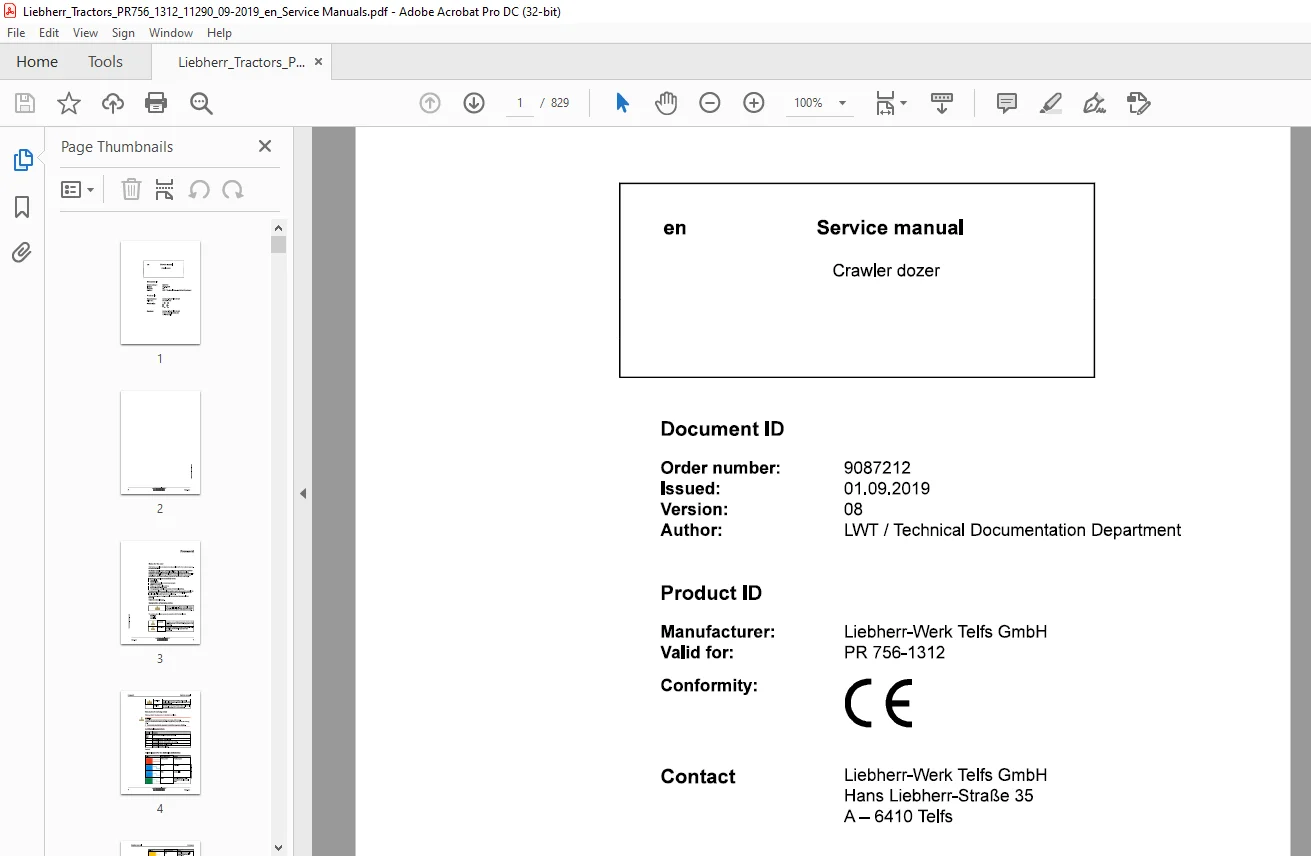
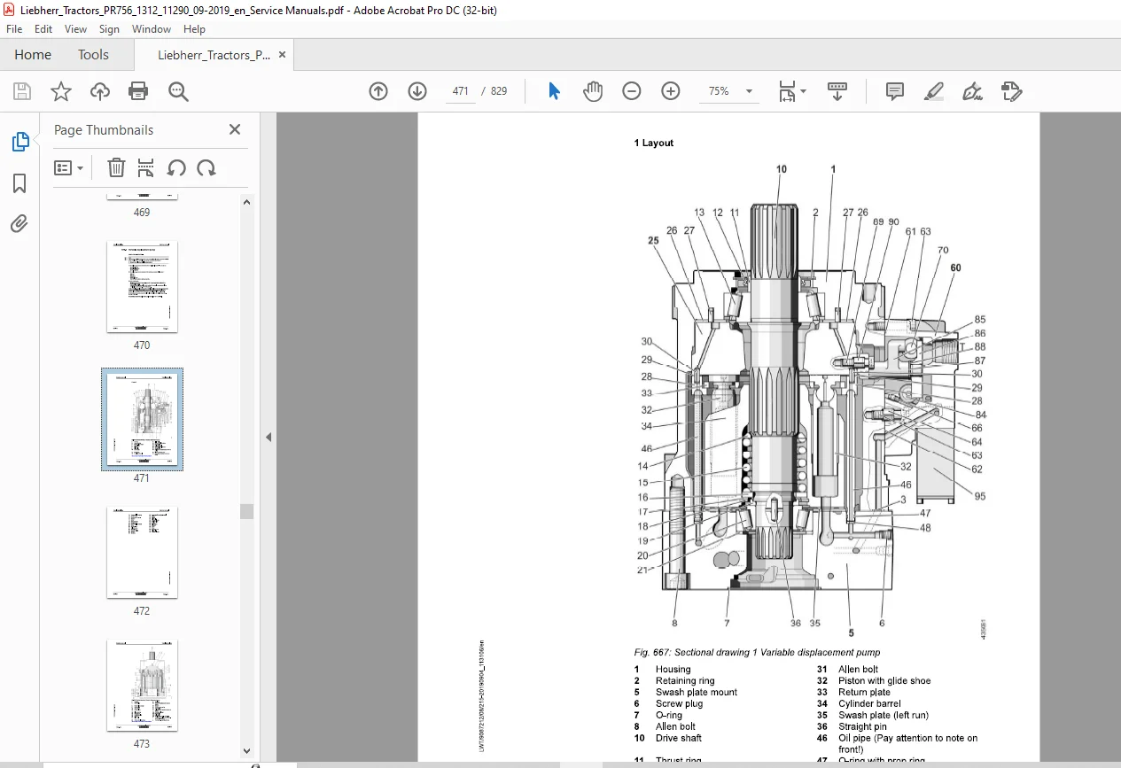
Liebherr Tractor PR 756 1312 Crawler dozer Service Manual – PDF DOWNLOAD
Original price was: $89.95.$33.95Current price is: $33.95.
Liebherr Tractor PR 756 1312 Crawler dozer Service Manual – PDF DOWNLOAD
Description
Liebherr Tractor PR 756 1312 Crawler dozer Service Manual – PDF DOWNLOAD
FILE DETAILS:
Liebherr Tractor PR 756 1312 Crawler dozer Service Manual – PDF DOWNLOAD
Language : English
Pages : 829
Downloadable : Yes
File Type : PDF
Size: 176 MB
DESCRIPTION:
Liebherr Tractor PR 756 1312 Crawler dozer Service Manual – PDF DOWNLOAD
This Service manual is intended for trained specialist staff in the Liebherr organization and its dealers.
The Service manual provides specific knowledge for the maintenance of Liebherr construction machinery. Basic technical knowledge of electrics, hydraulics, mechanics and Diesel engine technology are not detailed in this Service manual. A subject-based, qualified training is therefore necessary. Liebherr recommends participation on the Liebherr Training program for construction machinery.
In this Service manual you find information about:
For information relating to control and operation refer to the operator’s manual. For information relating to spare parts refer to the Spare parts catalog. Observe the locally applicable accident prevention regulations.
- Familiarize yourself with the operator’s manual before putting the machine into service. Also, ensure you have obtained, read, and understood any additional instructions regarding special accessories for the machine.
- Only authorized personnel may operate, maintain, or repair the machine. Remember to observe the minimum legal age limit.
- Utilize trained or instructed personnel and clearly define their responsibilities for operation, setup, maintenance, and repairs.
- Determine the machine operator’s responsibility, including adherence to traffic regulations, and empower them to refuse unsafe instructions from third parties.
- Do not allow untrained or trainee individuals to operate or work on the machine without constant supervision and guidance from an experienced instructor or operator.
- Periodically check and observe anyone operating or working on the machine to ensure they follow the safety instructions and guidelines provided in the operator’s manual.
- Always wear appropriate work clothing when operating or working on the machine. Avoid wearing rings, watches, ties, scarves, open jackets, or loose clothing that may pose a risk of injury by getting stuck or pulled in. Use prescribed safety equipment for specific tasks, such as safety glasses, safety shoes, safety helmets, work gloves, reflective vests, and ear protection.
- Consult the supervisor at the jobsite for special safety instructions and regulations.
- Maintain three-point contact when entering and exiting the machine.
- Never use joysticks as handholds when entering or exiting the machine to prevent inadvertent movement and serious accidents.
- Avoid jumping off the machine. Use designated steps, ladders, catwalks, and handles when climbing on or off the machine. Use both hands for support and face the machine.
- Keep steps, ladders, and handles free of oil, grease, mud, snow, and ice to minimize the risk of slipping, stumbling, or falling.
- Familiarize yourself with the emergency exit.
- If no other instructions are provided, follow this procedure for maintenance and repair work:
- Park the machine on solid and level ground.
- Bring all control levers to the neutral position.
- Set the parking switch to the park position.
- Turn off the engine and remove the ignition key.
- Actuate the control levers several times to relieve pressure in the servo lines.
- Bring all control levers to the neutral position.
- Before working on the hydraulic circuit, with the engine turned off and the ignition key in the contact position, move all pilot controls (joysticks and pedals) in both directions to relieve servo pressure and remaining back pressures in the working circuits. Then release the internal hydraulic tank pressure.
- Before leaving the operator’s seat, switch the parking switch to the park position.
- Secure all loose parts on the machine.
- Never operate the machine without conducting a complete walk-around inspection. Check if all warning signs are present on the machine and if they are legible.
- Observe all signs indicating danger and safety instructions.
IMAGES PREVIEW OF THE MANUAL:
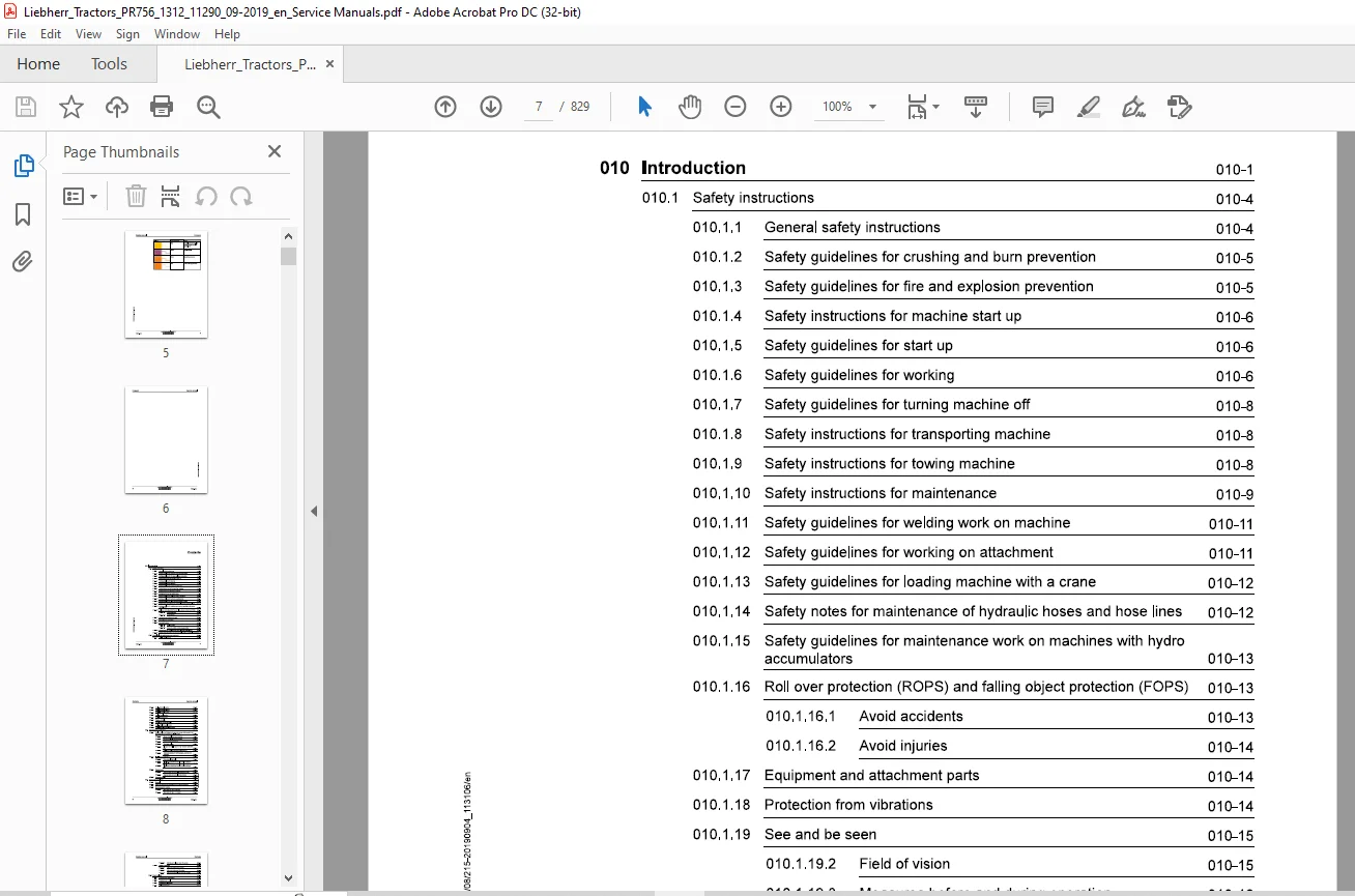
TABLE OF CONTENTS:
Liebherr Tractor PR 756 1312 Crawler dozer Service Manual – PDF DOWNLOAD
010.1 Safety instructions 010-4
0101.1 General safety instructions 010-4
010.1.2 Safety guidelines for crushing and burn prevention 010-5
010.1.3 Safety guidelines for fire and explosion prevention 010-5
010.14 Safety instructions for machine start up 010-6
0101.5 Safety guidelines for start up 010-6
010.1.6 Safety guidelines for working 010-6
0101.7 Safety guidelines for turning machine off 010-8
010.1.8 Safety instructions for transporting machine 010-8
010.1.9 Safety instructions for towing machine 010-8
010.1.10 Safety instructions for maintenance 010-9
010.1.11 Safety guidelines for welding work on machine 010-11
010.1.12 Safety guidelines for working on attachment 010-11
010.1.13 Safety guidelines for loading machine with a crane 010-12
010.1.14 Safety notes for maintenance of hydraulic hoses and hose lines 010-12
010.1.15 Safety guidelines for maintenance work on machines with hydro
accumulators 010-13
010.1.16 Roll over protection (ROPS) and falling object protection (FOPS) 010-13
010.1.16.1 Avoid accidents 010-13
010.1.16.2 Avoid injuries 010-14
010.1.17 Equipment and attachment parts 010-14
010.1.18 Protection from vibrations 010-14
010.1.19 See and be seen 010-15
010.1.19.2 Field of vision 010-15
010.1.19.3 Measures before and during operation 010-16
010.1.20 Safety notes for Diesel engines with electronic control units 010-17
010.1.21 Safety notes for working on Common Rail System of Diesel engines910-17
010.2 Special tools for maintenance and repair work 010-19
0102.1 Tools – Diesel engine 010-19
010.2.3 Tools – Hydraulic cylinder 010-27
010.2.4 Tools – Electrical system 010-28
010.25 Tools – Travel gearbox 010-30
010.26 Tools – Undercarriage 010-31
010.2.7 Tension unit tools 010-33
010.2.8 Lift cylinder suspension tools 010-33
010.2.9 Tools – Oscillating axle frame 010-34
010.2.10 Tools – Diesel exhaust fluid system 010-35
Standards and specifications 010-37
010.3.1 Preload values and tightening torques for screws with standard and
fine metric thread according to DIN ISO 261 010-37
010.3.1.1 Scope of application and purpose 010-37
010.3.1.2 Further applicable documentation 010-37
010.3.1.3 Changes and descriptions 010-38
010.3.1.4 Tightening values 010-38
010.3.1.5 Flanges and half flanges for high pressure (standard
62) 010-44
010.3.1.6 Half flange for low pressure (standard 61) 010-44
010.3.1.7 Tightening torques for cutting edges, end bits and
adapters 010-44
010.3.2 Installation specifications 010-45
010.3.2.1 Duo cone slipring seals 010-45
010.3.2.2 Installation instructions for axle shell mounting of
track roller 010-48
010.3.2.3 Installation instructions for axle shell mounting of
idler 010-49
010.3.3 Tapping bores 010-49
010.3.3.1 Tapping bores of metric ISO standard threads 010-49
010.3.3.2 Tapping bores of metric ISO fine threads 010-51
010.3.4 Conversion tables 010-54
Conservation guidelines 010-55
010.41 General 010-55
010.4.2 Taking the machine out of service for an unknown duration 010-55
010.4.3 Shut down of the machine 010-56
010.4.3.1 Shut down for up to 2 months 010-56
0104.3.2 Shut down for up to 12 months 010-57
010.44 Return to operation 010-58
010.4.4.1 After a shut down of 2 months 010-58
010.4.4.2 After a shut down of 12 months 010-58
010.4.4.3 After shut down of longer than 12 months 010-59
010.5 Repair welding 010-60
010.5.1 Preparation of cracked part 010-60
010.5.1 Preparation of a weld 010-61
0105.1 Treatment of electrodes 010-61
0105.1 Welding technique 010-61
0105.1 Reinforcement of welding seam 010-62
010.5.1 General use of reinforcement sheeting 010-62
010.5.1.1 Form of sheeting 010-62
010.5.1.1 Thickness of sheeting 010-62
010.5.1.1 Material quality of sheeting 010-63
010.5.1.1 Application of reinforcement sheeting 010-63
010.5.1.1 Welding the reinforcement sheeting 010-63
010.5.1.1 Selection of correct welding electrodes 010-64
010.5.1.2 Electrode selection 010-64
010.5.1.2 Steel chart 010-65
010.5.1.2 Welding additives chart 010-66
010.6 Hydraulic symbols 010-70
010.7 Electrical symbols 010-80
010.8 Material weights 010-84
020 Technical data 020-1
020.1 Overall machine 020-3
020.1.1 Overall machine – Full overview
PR756-1312/11290~; 020-3
020.2 Drive group 020-5
020.2.1 Diesel engine
PR756-1312/11290~; 020-5
0202.2 Clutch
PR756-1312/11290-; 020-6
020.2.3 Splitterbox
PR756-1312/11290-; 020-7
020.3 Cooling system 020-8
020.3.1 Regulator pump for coolant circuit
PR756-1312/11290-; 020-8
020.3.2 Gear motor Fan drive hydraulic oil cooler
PR756-1312/11290-; 020-8
020.3.3 Axial piston motor fan drive of water and charge air cooler
PR756-1312/11290-; 020-8
020.4 Working hydraulics 020-9
020.4.1 Regulating pump Working hydraulic
PR756-1312/11290-; 020-9
020.4.2 Proportional control valve block
PR756-1312/11290-; 020-9
020.4.3 Lift cylinder
PR756-1312/11290-; 020-9
020.4.4 Tilt cylinder
PR756-1312/11290-; 020-10
020.5 Travel hydraulics 020-11
020.5.1 Gear pump replenishing and pilot control working hydraulic
PR756-1312/11290-; 020-11
020.5.2 Variable displacement pump
PR756-1312/11290-; 020-11
020.5.3 Variable displacement motor
PR756-1312/11290-; 020-11
020.6 Hydraulic components 020-12
020.6.1 Hydraulic tank
PR756-1312/11290-; 020-12
020.7 Electrical system 020-13
020.7.1 Batteries – Installation
PR756-1312/11290-; 020-13
020.8 Travel gearbox 020-14
020.8.1 Travel gearbox
PR756-1312/11290-; 020-14
020.8.2 Brake system
PR756-1312/11290-; 020-15
020.9 Travel gear, axles, tyres, drive shafts 020-16
020.9.1 Travel gear frame
PR756-1312/11290-; 020-16
020.9.2 Idler
PR756-1312/11290-; 020-16
020.9.3 Tension unit
PR756-1312/11290-; 020-16
020.9.4 Track roller
PR756-1312/11290-; 020-16
PR756-1312/11290-; 020-17
020.9.6 Track chain
PR756-1312/11290~; 020-17
020.9.7 Sprocket
PR756-1312; 020-17
020.10 Working attachment 020-19
020.10.1 Straight blade
PR756-1312/11290-; 020-19
020.10.2 Cutting angle adjustment for blade
PR756-1312/11290-; 020-20
020.10.3 Ripper with cutting angle adjustment
PR756-1312/11290-; 020-21
020.10.4 Quick coupler Ripper tooth
PR756-1312/11290-; 020-22
030 Maintenance 030-1
030.1 Maintenance and inspection schedule 030-8
030.2 Fill quantities, lubrication schedule 030-14
030.2.1 Recommended lubricants
PR756-1312/11290~; 030-14
030.2.2 Recommended fuel and operating fluids
PR756-1312/11290-; 030-15
030.2.3 Lubrication schedule
PR756-1312; 030-15
030.3 Lubricants and fuels 030-18
030.3.1 General information about lubricants and fuels 030-18
030.3.1.1 General Information 030-18
030.3.1.2 General questions 030-18
030.3.1.3 Safety data sheets 030-18
030.3.1.4 Technical data sheets 030-18
030.3.1.5 Specific Liebherr standards 030-18
030.3.2 Diesel fuels
PR756-1312/11290-; 030-19
030.3.2.1 Minimum quality requirement 030-19
030.3.3 Engine oils
PR756-1312/11290-; 030-19
030.3.3.1 Liebherr recommendation 030-19
030.3.3.1 Other approved engine oils 030-19
030.3.3.2 Minimum quality requirement 030-19
030.3.3.3 Aggravating circumstances 030-20
030.3.4 Coolant
PR756-1312/11290-; 030-20
030.3.4.1 Requirements for water used 030-20
030.3.4.2 Corrosion inhibitor 030-21
030.3.4.2 Liebherr recommendation 030-21
030.3.4.2 Anti-freeze and corrosion protection agent 030-21
030.3.4.2 Liebherr recommendation 030-21
030.3.4.2 Minimum quality requirement 030-21
030.3.5 Diesel exhaust fluids
PR756-1312/11290-; 030-22
030.3.5.1 Liebherr recommendation 030-22
030.3.5.2 Minimum quality requirement 030-22
030.3.6 Hydraulic oil
PR756-1312/11290-; 030-22
030.3.6.1 Liebherr Hydraulic oil 030-22
030.3.6.2 Engine oil as hydraulic oil 030-23
030.3.6.3 Warm up specification 030-23
030.3.6.4 Biodegradable hydraulic oils 030-24
030.3.6.5 Oil change, oil analysis, filter change 030-24
030.3.7 Lube oils for splitterboxes
PR756-1312/11290~; 030-27
030.3.7.1 Quality 030-27
030.3.7.2 Viscosity 030-28
030.3.8 Lube oils for travel gearbox
PR756-1312/11290~; 030-28
030.3.8.1 Quality 030-28
030.3.8.2 Viscosity 030-29
030.3.8.3 Oil change 030-29
030.3.9 Oil for duo cone (slipring) seal Travel gear
PR756-1312; 030-29
030.3.10 Grease and other lubricants
PR756-1312/11290-; 030-30
030.3.11 Qil for hinges and joints
PR756-1312; 030-31
030.3.12 OQil for axle bearing
PR756-1312; 030-32
030.4 Maintenance tasks 030-33
0304.1 Safety instructions for maintenance
PR756-1312; 030-33
030.4.2 Maintenance – preparations 030-33
030.4.2.1 Maintenance position
PR756-1312/11290-; 030-33
030.4.2.2 Turn the electrical system off
PR756-1312/11290-; 030-36
030.4.2.3 Raising the operator’s cab hydraulically
PR756-1312/11290-; 030-36
030.4.2.4 Lower the operator’s cab hydraulically
PR756-1312/11290-; 030-39
030.4.3 Overall machine 030-41
030.4.3.1 Checking the machine for external damage, correct
maintenance and proper condition
PR756-1312; 030-41
030.4.3.2 Lubricating all lube points according to lubrication
chart
PR756-1312; 030-42
030.4.3.3 Checking the window wiper
PR756-1312/11290-; 030-42
030.4.3.4 Oil samples and oil analysis
PR756-1312/11290-; 030-42
030.4.3.5 Wet cleaning the machine
PR756-1312/11290-; 030-46
030.4.3.6 Protecting the piston rods
PR756-1312/11290-; 030-48
030.4.3.7 Taking the machine out of service
PR756-1312; 030-48
0304.4 Drive group 030-48
030.4.4.1 Check the engine oil level
PR756-1312/11290-; 030-48
030.4.4.2 Changing engine oil
PR756-1312/11290-; 030-49
030.4.4.3 Changing the lube oil filters
PR756-1312/11290-; 030-51
belly pans for contamination and cleaning them
030.4.4.5 Checking the ribbed V-belt and adjusting it if
030.4.4.6 Changing belt drive
030.4.4.8 Check the supply and exhaust lines for mounting and
0304.4.9 Check the electrical system of the Diesel engine
030.4.4.10 Change oil separator filter cartridge
0304.4.11 Checking and changing heat flange
030.4.4.12 Checking engine mount, oil pan and engine brackets
030.4.4.13 Checking tightening torque of profile clamp
030.4.4.14 Notes for work on the fuel system
030.4.4.15 Fuel preliminary filter: Drain the condensation
030.4.4.16 Fuel tank: Drain condensation and sediments
030.4.4.17 Change fuel preliminary filter cartridge
030.4.4.18 Changing fuel fine filter
0304.4.19 Empty and clean the fuel tank
030.4.4.20 Venting fuel system
0304.4.22 Replacing the air filter
030.4.4.23 Clean the dust discharge valve
030.4.4.24 Splitterbox: Check the oil level
030.4.4.25 Splitterbox: Change the oil
Cooling system 030-76
030.4.5.1 Check the coolant level
030.4.5.2 Clean the cooling system
0304.5.3 Check the cooling system
PR756-1312/11290~; 030-81
030.4.5.5 Change the coolant
PR756-1312/11290~; 030-88
0304.6 Travel hydraulics 030-31
030.4.6.1 Changing the supply circuit filter
PR756-1312/11290-; 030-91
0304.7 Hydraulic components 030-95
030.4.7.1 Check the oil level in the hydraulic tank and add oil
PR756-1312/11290-; 030-95
030.4.7.2 Clean the magnetic rod on the hydraulic tank
PR756-1312/11290-; 030-98
030.4.7.3 Checking the hydraulic system for function and leaks
PR756-1312/11290~; 030-99
030.4.7.4 Clean the oil cooler
PR756-1312/11290~; 030-100
030.4.7.5 Changing the hydraulic oil
PR756-1312/11290~; 030-101
030.4.7.6 Draining water and sediments in the hydraulic tank
PR756-1312/11290-; 030-104
030.4.7.7 Change the return filter insert
PR756-1312/11290~; 030-104
030.4.8 Electrical system 030-106
030.4.8.1 Check the display unit and lighting
PR756-1312/11290-; 030-106
030.4.8.2 Check the batteries
PR756-1312/11290~; 030-106
0304.9 Travel gearbox 030-109
030.4.9.1 Travel gearbox: checking the condition
PR756-1312; 030-109
030.4.9.2 Check the oil level
PR756-1312/11290-; 030-109
030.4.9.3 Change the oil
PR756-1312/11290~; 030-110
030.4.9.4 Checking the oil level in the duo cone (slip ring) area
PR756-1312/11290-; 030-110
030.4.9.5 Change the oil in the duo cone (slip ring) area
PR756-1312/11290~; 030-112
030.4.10 Travel gear, axles, tyres, drive shafts 030-116
030.4.10.1 Checking the nuts and bolts of the travel gear
PR756-1312/11290-; 030-116
030.4.10.2 Checking the carrier rollers, track rollers and idlers
for tightness
PR756-1312/11290-; 030-118
030.4.10.3 Check and adjust the idler guides
PR756-1312/11290~; 030-118
030.4.10.4 Check and adjust the chain tension
PR756-1312/11290-; 030-122
030.4.10.5 Change the chain
PR756-1312/11290~; 030-125
030.4.10.6 Checking the travel gear wear
PR756-1312/11290-; 030-131
030.4.10.7 Checking travel gear guides
PR756-1312/11290~; 030-132
030.4.10.8 Checking oil fill of axle bearings
PR756-1312/11290-; 030-135
030.4.10.9 Grease the equalizer bar bearing
PR756-1312/11290~; 030-136
030.4.10.10 Checking oil level of track carriers
PR756-1312/11290~; 030-136
030.4.10.11 Checking idler spacing and adjusting it, if necessary
PR756-1312/11290-; 030-137
030.4.10.12 Check the screws on the front side of the axle
bearing for tight seating
PR756-1312/11290~; 030-139
030.4.11 Working attachment 030-140
030.4.11.1 Checking the cutting edges, corners and ripper teeth
for wear
PR756-1312/11290-; 030-140
0304.11.2 Check the center position and mounting
PR756-1312/11290~; 030-141
030.4.11.3 Check the working equipment
PR756-1312/11290-; 030-141
030.4.11.4 Checking the bearing points of the working attach-
ment for play and wear
PR756-1312; 030-141
030.4.11.5 Checking the mounting screws and pin retainers of
the working attachment for tight seating
PR756-1312; 030-143
030.4116 Removing and installing the ripper tooth tips
PR756-1312/11290-; 030-143
030.4.12 Operator’s cab, heating, air conditioning 030-147
030.4.12.1 Checking the heating for function and leaks
PR756-1312/11290-; 030-147
030.4.12.2 Clean and change the recirculating – fresh air filter
PR756-1312/11290~; 030-148
specialist staff
030.4.124 Check the compressor mounting
PR756-1312/11290-; 030-149
030.4.12.5 To check the capacitor
PR756-1312/11290-; 030-150
030.5 Testing and adjustment checklist
PR756-1312/11290-; 030-151
0305.1 Adjustment checklist 030-151
030.5.2 Track Components Check List 030-162
030.5.2.1 Test report 030-162
030.5.2.2 Wear data 030-166
Check and adjustment tasks 030-169
0306.1 Safety instructions
PR756-1312; 030-169
030.6.2 Overall machine 030-170
030.6.2.1 Preparations for adjustment procedures
PR756-1312/11290-; 030-170
030.6.2.2 Visual inspection and maintenance
PR756-1312/11290-; 030-172
030.6.2.3 Bringing machine to operating temperature
PR756-1312/11290-; 030-173
operating temperature:
PR756-1312/11290-; 030-173
mining adjustment range
Cooling system 030-177
030.6.4.1 Checking the stand-by pressure for the fan control
030.6.4.2 Checking pressure relief valve — fan motor and fan
Working hydraulics 030-184
PR756-1312/11290-; 030-184
control valve block
PR756-1312/11290~; 030-185
control valve block
PR756-1312/11290-; 030-186
0306.5.4 Checking the pressure cut off
PR756-1312/11290-; 030-188
030.6.5.5 Checking the pressure difference HD-LS
PR756-1312/11290-; 030-189
0306.5.6 Checking the nitrogen fill in the hydro accumulator
PR756-1312/11290~; 030-190
030.6.6 Travel hydraulics 030-190
030.6.6.1 Checking the supply pressure of the variable pump
PR756-1312/11290-; 030-190
030.6.6.2 Checking the hydraulic neutral position of the vari-
able displacement pumps
PR756-1312/11290-; 030-191
0306.6.3 Checking the pressure limitation for high pressure
PR756-1312/11290-; 030-193
030.6.7 Electrical system 030-194
030.6.7.1 Calibrating the hydrostat
PR756-1312/11290-; 030-194
030.6.7.2 Checking travel joystick
PR756-1312/11290-; 030-205
030.6.7.3 Calibrating inching brake pedal
PR756-1312/11290-; 030-218
030.6.7.4 Brake test
PR756-1312/11290-; 030-225
0306.7.5 Overspeed safety test (option)
PR756-1312/11290-; 030-229
030.6.7.6 Parameter adjustment options
PR756-1312/11290-; 030-231
040 Drive group 040-1
040.1 Diesel engine 040-2
Fuel system 040-7
040.1.2.1 Fuel system
040.1.2.2 Fuel quantity sensor
040.1.2.4 Fuel tank
Air filter system 040-11
040.14 Exhaust system 040-14
040.1.4.1 Exhaust system – full overview
PR756-1312/11290~; 040-15
040.1.4.2 Selective catalytic reduction – SCR
PR756-1312/11290-; 040-16
0401.5 Diesel engine mounting
PR756-1312/11290~; 040-19
040.2 Clutch
PR756-1312/11290~; 040-21
040.3 Splitterbox
PR756-1312/11290~; 040-23
040.4 Couplings – Pump output
PR756-1312/11290~; 040-26
050 Cooling system 050-1
050.1 Cooling system, complete
PR756-1312/11290~; 050-2
050.2 Cooler arrangement 050-5
050.21 Combi cooler
PR756-1312/11290~; 050-6
050.3 Hydraulic 050-12
050.3.1 Regulating pump
PR756-1312/11290~; 050-12
050.3.2 Gear motor — fan oil cooler
PR756-1312/11290~; 050-16
050.3.3 Axial piston fixed displ. motor — fan drive
PR756-1312/11290~; 050-17
050.3.4 Pump regulation
PR756-1312/11290-; 050-19
060 Working hydraulics 060-1
060.1 Working hydraulics – Full overview
PR756-1312/11290~; 060-2
060.2 Regulating pump 060-14
0602.1 Regulating pump – Full overview
PR756-1312/11290~; 060-15
060.3 Proportional control valve block 060-21
060.3.1 Proportional control valve block – Full overview
PR756-1312/11290~; 060-22
060.4 Pilot control Working hydraulic 060-28
060.4.1 Pilot control – Full overview
PR756-1312/11290-; 060-28
060.5 Hydraulic cylinder 060-35
060.5.1 Lift cylinder
PR756-1312/11290-; 060-35
060.5.2 Tilt cylinder with half shell bearings
PR756-1312/11290-; 060-37
070 Travel hydraulics 070-1
070.1 Full overview – Travel hydraulic
PR756-1312/11290-; 070-2
070.2 Gear pump – replenishing
PR756-1312/11290-; 070-12
070.3 Variable displacement pump
PR756-1312/11290~; 070-14
070.4 Variable displacement motors 070-22
070.4.1 Variable displacement motor
PR756-1312/11290-; 070-22
070.5 Distributor block 070-32
070.5.1 Parking brake, solenoid valve
PR756-1312/11290-; 070-33
070.5.2 Pressure relief valve – replenishing
PR756-1312/11290-; 070-35
080 Hydraulic components 080-1
080.1 Hydraulic cylinder 080-2
080.1.1 Ripper cylinder
PR756-1312/11290-; 080-2
080.1.2 Valves
PR756-1312/11290-; 080-3
080.2 Hydraulic tank 080-16
080.2.1 Hydraulic tank
PR756-1312/11290-; 080-16
100 Brake system 100-1
100.1 Inching brake pedal 100-2
100.1.1 Speed reduction pedal
PR756-1312/11290-; 100-2
110 Electrical system 110-1
110.1 Electrical system – Full overview
PR756-1312/11290-; 110-2
PR756-1312/11290-; 110-5
110.3 Circuit diagrams
PR756-1312/11290~; 110-8
110.4 Electrical components in operator’s cab
PR756-1312/11290-; 110-9
110.4.2 Central control (Master 100)
PR756-1312/11290-; 110-16
110.4.3 Travel sensor
PR756-1312/11290-; 110-18
110.44 Speed control
PR756-1312/11290~; 110-20
110.5 Electrical components – Diesel engine
PR756-1312/11290-; 110-22
110.6 Electrical components – Main frame
PR756-1312/11290~; 110-27
110.7 Electrical components Compartments 110-31
110.7.1 Battery compartment
PR756-1312/11290-; 110-31
110.7.2 Fuel tank
PR756-1312/11290-; 110-33
110.7.3 Central electrical system compartment
PR756-1312/11290-; 110-36
110.7.4 Hydraulic tank
PR756-1312/11290~; 110-43
110.8 Display unit
PR756-1312/11290-; 110-45
120 Travel gearbox 120-1
120.1 Travel gearbox, overall
PR756-1312/11290~; 120-2
120.2 Brake system
PR756-1312/11290-; 120-8
120.3 Duo cone slipring seal
PR756-1312/11290-; 120-9
120.4 External oil supply
PR756-1312/11290~; 120-10
130 Travel gear, axles, tyres, drive shafts 130-1
130.1 Travel gear frame 130-2
130.1.1 Support frame
PR756-1312/11290-; 130-2
130.2 Idler
130.4 Tension unit — removal
PR756-1312/11290-; 130-16
130.5 Tension unit — installation
PR756-1312/11290~; 130-22
130.5.1.1 Preparation notes 130-22
130.5.1.2 Installation of tension unit on rigid travel gear and
single pendulum travel gear 130-23
130.6 Track roller
PR756-1312/11290-; 130-29
130.7 Carrier roller
PR756-1312/11290~; 130-30
130.8 Function, wear and evaluation
PR756-1312; 130-31
140 Steel components Basic machine 140-1
140.1 Lift cylinder suspension
PR756-1312/11290~; 140-2
140.2 Equaliser bar
PR756-1312/11290~; 140-3
140.3 Push frame (outside)
PR756-1312/11290-; 140-6
150 Working attachment 150-1
160.1 Straight blade
PR756-1312/11290-; 150-2
150.2 Hydraulic cutting angle adjustment
PR756-1312/11290~; 150-3
150.3 Ripper
PR756-1312; 150-11
150.4 Cutting angle adjustment – Ripper
PR756-1312/11290~; 150-12
160 Operator’s cab, heating, air conditioning 160-1
160.1 Operator’s platform 160-2
160.1.1 Operator’s platform Attachments
PR756-1312/11290~; 160-2
160.1.2 Operator’s platform bearing
PR756-1312/11290-; 160-3
160.1.3 Support cylinder
PR756-1312/11290~; 160-5
160.2 Operator’s cab 160-9
PR756-1312/11290-; 160-9
160.3 Heating, ventilation, air conditioning 160-10
160.3.1 Heating and air conditioning system 160-10
160.3.1.1 Heating, air conditioning and ventilation
PR756-1312/11290-; 160-10
190 Options 190-1
190.1 Refueling pump
PR756-1312/11290-; 190-2
190.2 Reversible fan drive
PR756-1312/11290-; 190-7
200 Service codes, Diagnostics 200-1
200.2 Testing and adjustment software 200-2
200.21 Wizard test and adjustment software 200-2
200.2.1.1 General 200-2
200.2.1.2 Symbols 200-3
200.2.1.3 Information window 200-73
Questions? Email us: [email protected]
PLEASE NOTE:
- This is the same manual used by the dealers to diagnose and troubleshoot your vehicle
- You will be directed to the download page as soon as the purchase is completed. The whole payment and downloading process will take anywhere between 2-5 minutes
- Need any other service / repair / parts manual, please feel free to contact [email protected] . We still have 50,000 manuals unlisted
S.V