Liebherr Tractor PR 766 1296 Crawler Dozer Operator’s Manual 15137 – PDF DOWNLOAD
Original price was: $86.95.$28.95Current price is: $28.95.
Liebherr Tractor PR 766 1296 Crawler Dozer Operator’s Manual 15137 – PDF DOWNLOAD
Product ID
Manufacturer: Liebherr-Werk Telfs GmbH
Type: PR 766
Type no.: 1296
From Serial no.: 15137
Description
Liebherr Tractor PR 766 1296 Crawler Dozer Operator’s Manual 15137 – PDF DOWNLOAD
FILE DETAILS:
Liebherr Tractor PR 766 1296 Crawler Dozer Operator’s Manual 15137 – PDF DOWNLOAD
Language : English
Pages : 338
Downloadable : Yes
File Type : PDF
Size: 71.4 MB
DESCRIPTION:
Liebherr Tractor PR 766 1296 Crawler Dozer Operator’s Manual 15137 – PDF DOWNLOAD
Product ID
Manufacturer: Liebherr-Werk Telfs GmbH
Type: PR 766
Type no.: 1296
From Serial no.: 15137
Preface:
This operator’s manual has been written for the operator and for the maintenance
staff of the machine.
It contains the descriptions for:
– Chapter 1 “Product description”
– Chapter 2 “Safety instructions”
– Chapter 3 “Control, operation”
– Chapter 4 “Malfunctions”
– Chapter 5 “Maintenance”
The operator’s manual must be read and used carefully by all persons who carry
out work with or on the machine before putting the machine into service for the first
time and later, at regular intervals.
Work with or on the machine includes, for example:
Operation including set up, troubleshooting during work procedure, disposal of production wastes, care, disposal of service and auxiliary materials.
Service including maintenance, inspection and repair work
Transport or loading the machine
This allows the machine operator to familiarize himself with the machine more
easily and prevent malfunctions due to improper operation.
Observation of the operator’s manual by maintenance staff:
– increases reliability in use
– extends the service life of your machine
– reduces repair costs and downtime
- The operator’s manual belongs with the machine. Make sure that a copy is
always readily available in the operator’s cab. - The operator’s manual should be supplemented with instructions for accident
prevention and environmental protection based on existing national regulations.
In addition to the operator’s manual and legally binding regulations on accident
prevention which apply in the user country and at point of use, authorized specialist
rules for safe and correct working procedures are also to be observed. - These operator’s manual contains all required information for control, operation
and maintenance of your machine. - Some illustrations in this operator’s manual may depict details and working devices
which differ to your machine. - In some illustrations, protective devices and covers have been removed in the
interests of better presentation. - Improvements, which are always being incorporated into our machines, may result
in changes to your machine which are not yet indicated in this operator’s manual. - If you need additional explanations or instructions, please don’t hesitate to contact
the Technical Documentation and Service Department.
IMAGES PREVIEW OF THE MANUAL:
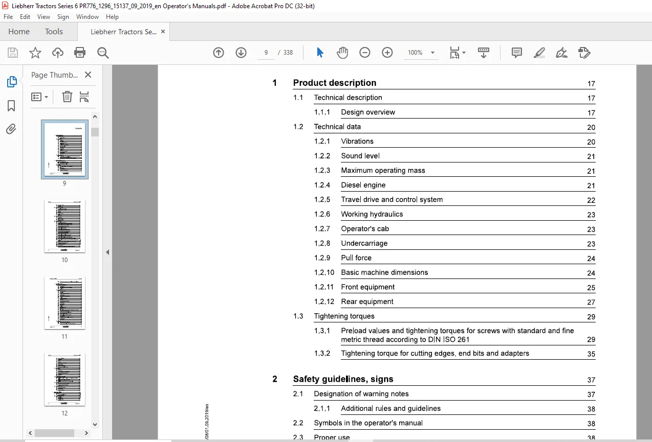
TABLE OF CONTENTS:
Liebherr Tractor PR 766 1296 Crawler Dozer Operator’s Manual 15137 – PDF DOWNLOAD
1 Product description 17
1.1 Technical description 17
1.1.1 Design overview 17
1.2 Technical data 20
1.2.1 Vibrations 20
1.2.2 Sound level 21
1.2.3 Maximum operating mass 21
1.2.4 Diesel engine 21
1.2.5 Travel drive and control system 22
1.2.6 Working hydraulics 23
1.2.7 Operator’s cab 23
1.2.8 Undercarriage 23
1.2.9 Pull force 24
1.2.10 Basic machine dimensions 24
1.2.11 Front equipment 25
1.2.12 Rear equipment 27
1.3 Tightening torques 29
1.3.1 Preload values and tightening torques for screws with standard and fine
metric thread according to DIN ISO 261 29
1.3.2 Tightening torque for cutting edges, end bits and adapters 35
2 Safety guidelines, signs 37
2.1 Designation of warning notes 37
Additional rules and guidelines 38
2.2 Symbols in the operator’s manual 38 ~
2.3 Proper use 38 .;:,:: 0 2.3.1 Laws, rules, guidelines and safety regulations 38
~ 2.3.2 Intended use 38
2.3.3 Foreseeable misuse 39
2.3.4 Danger area of the machine 40
2.3.5 Operating conditions 41
2.3.6 Disposal 42
2.4 Description of personnel 43
2.4.1 Personal protective equipment 43
2.4.2 Requirements for personnel 43
2.4.3 Operator 43
2.4.4 Operator 44
2.4.5 Maintenance staff 45
2.4.6 Guide 46
2.5 Signs on the machine 46
2.5.1 Safety signs 46
2.5.2 Information signs 54
2.5.3 Identification plates 61
2.6 Safety instructions 62
2.6.1 General safety instructions 62
2.6.2 Safety guidelines for crushing and burn prevention 64
2.6.3 Safety guidelines for fire and explosion prevention 64
2.6.4 Safety instructions for machine start up 65
2.6.5 Safety guidelines for start up 65
2.6.6 Safety guidelines for working 65
2.6.7 Safety guidelines for turning machine off 66
2.6.8 Safety instructions for transporting machine 67
2.6.9 Safety instructions for towing machine 67
2.6.10 Safety instructions for maintenance 68
2.6.11 Safety guidelines for welding work on machine 70
2.6.12 Safety guidelines for working on attachment 70
2.6.13 Safety guidelines for loading machine with a crane 71
2.6.14 Safety notes for maintenance of hydraulic hoses and hose lines 71
2.6.15 Safety guidelines for maintenance work on machines with hydro accu- ,!!?
“0′ mulators 72
2.6.16 Roll over protection (ROPS) and falling object protection (FOPS) 72 :ii
2.6.17 Equipment and attachment parts 73
2.6.18 Protection from vibrations 73
2.6.19 See and be seen 74
2.6.20 Safety notes for Diesel engines with electronic control units 76
2.6.21 Safety notes for working on Common Rail System of Diesel engines 76
3 Control, operation 79
3.1 Operating and control elements 80
3.1.1 Operator’s cab 80
3.1.2 Control elements on the operator’s platform 82
3.1.3 Display unit 87
3.2 Operation 126
3.2.1 Battery main switch 126
3.2.2 Access light 127
3.2.3 Entering and exiting the machine 128
3.2.4 Emergency exit 128
3.2.5 Using emergency hammer (option) 130
3.2.6 Door lock 130
3.2.7 Premium operator’s seat 132
3.2.8 Safety belt 138
3.2.9 Adjust the armrests and joysticks 140
3.2.10 Heating system 141
3.2.11 Air conditioning 143
3.2.12 Sliding window 148
3.2.13 Sun blind 148
3.2.14 Interior lighting of cab 149
3.2.15 Inside mirror 150
3.2.16 Electrical windscreen wiper system and windscreen washer system 150
3.2.17 Compartment for documentation 153
3.2.18 Turn the engine compartment lighting on 153
3.2.19 Reversing warning device 154
3.2.20 Disengageable reversing warning device 155
3.2.21 Fire extinguisher 156
3.2.22 Assembly of third party installations in the cab 157
3.2.23 Rotating beacon 158 3.2.24 LiDAT (option) 158
3.3 Operation 159
3.3.1 Operating machine on a daily basis 159
3.3.2 Using the machine at low or high ambient temperatures 165
3.3.3 Starting diesel engine 165
3.3.4 Travel mode 170
3.3.5 Driving 176
3.3.6 Braking 178
3.3.7 Taking machine out of service 180
3.3.8 Working in water 185
3.3.9 Working with attachment 186
3.3.10 Working with optional attachments 195
3.4 Work methods 201
3.4.1 Grading 201
3.4.2 Fine grading 202
3.4.3 Using several machines simultaneously 203
3.4.4 Creating and banking up trenches 204
3.4.5 Land clearing 205
3.4.6 Ripping 207
3.5 Install and remove the attachment 209
3.5.1 Installation guidelines for installation and removal of working attachment
3.5.2 Install the bearing shells of the attachment 209
3.5.3 Installing and removing push frame with straight blade 211
3.6 Transport 223
3.6.1 Transporting machine by truck or rail 223
3.6.2 Loading the machine with the crane 228
3.7 Emergency operations 231
3.7.1 Emergency mode function 231
3.7.2 Towing machine 231
3.7.3 Jump start procedure 239
4 Operating problems 241
4.1 Servicecodes 241 “0′
4.1.1 Service code – Display unit
4.2 Problems – Cause – Remedy 243
4.2.1 Diesel engine 243
4.2.2 Hydraulic system 245
4.2.3 Travel gear, tracks 246
copyright© Liebherr-Well< Telfs GmbH 2019
12 llEBHERR PR776-1296 / 15137
Operator’s manual Contents
4.2.4 Electrical system 246
4.2.5 Heating system 246
4.2.6 Working attachments 247
4.3 Problem remedy 248
4.3.1 Changing the fuses and relays 248
5 Maintenance 257
5.1 Maintenance and inspection schedule 257
5.2 Fill quantities, lubrication schedule 262
5.2.1 Recommended lubricants 262
5.2.2 Recommended fuel and operating fluids 263
5.2.3 Lubrication chart 263
5.2.4 Symbols in the lubrication chart 265
5.3 Lubricants and fuels 266
5.3.1 General information about lubricants and fuels 266
5.3.2 Diesel fuels 266
5.3.3 Lubricating oils for Diesel engines 267
5.3.4 Coolant for Diesel engines 269
5.3.5 Hydraulic oil 272
5.3.6 Lube oils for splitterboxes 277
5.3.7 Lube oils for travel gearbox 278
5.3.8 Oil for duo cone (slipring) seal Travel gear 279
5.3.9 Oil for axle bearing 279
5.3.10 Grease and other lubricants 280
5.3.11 Oil for hinges and joints 281
5.4 Take oil samples 282
5.4.1 Oil samples and oil analysis 282
5.5 Preparatory maintenance tasks 286
5.5.1 Safety instructions for maintenance 286
5.5.2 Maintenance position 286
5.5.3 Turn the electrical system off 289 ~ ;::: ., 5.6 Overall machine 291
~ 5.6.1 Lubricating all lube points according to lubrication chart 291
5.6.2 Checking the window wiper 291
5.7 Diesel engine 292
5.7.1 Checking the engine oil level 292
5.7.2 Checking the diesel engine configuration and the belly pans for contamination
and cleaning them 293
5.8 Cooling system 294
5.8.1 Check the coolant level and refill 294
5.8.2 Check the cooling system for contamination and clean it 296
5.9 Fuel system 299
5.9.1 Notes for work on the fuel system 299
5.9.2 Fuel preliminary filter: Drain the condensation 299
5.9.3 Fuel tank: Drain condensation and sediments 300
5.9.4 Empty and clean the fuel tank 301
5.10 Air filter system 304
5.10.1 Replacing the air filter 304
5.11 Hydraulic system 307
5.11.1 Checking the oil level in the hydraulic tank and topping up oil 307
5.12 Splitterbox 311
5.12.1 Splitterbox: Check the oil level 311
5.13 Electrical system 312
5.13.1 Check the display unit and lighting 312
5.13.2 Change the light bulbs 312
5.14 Heater, ventilation, air conditioning system 313
5.14.1 Inspection of the air conditioning system by HVAC specialist staff 313
5.14.2 To check the capacitor 313
5.15 Drive gear 314
5.15.1 Travel gearbox: checking the condition 314
5.15.2 Check the oil level in the duo cone (slipring) area 314
5.16 Track components 316
5.16.1 Checking the nuts and bolts of the travel gear components are firmly
seated 316
5.16.2 Checking and adjusting the track tension
5.16.3 Greasing equaliser bar bearing 321
5.17 Working attachment 323
5.17.1 Checking the cutting edges, corners and ripper teeth for wear 323 0
5.17.2 Lubricate the working attachment and hoist cylinder bearing 323
5.17.3 Checking the mounting screws and pin retainers of the working attachment
for tight seating 324
5.17.4 Removing and installing the ripper tooth tips
5.18 Cleaning the machine
5.18.1 Wet cleaning the machine
5.19 Preservation tasks
5.19.1 Protecting the piston rods
5.19.2 Taking the machine out of service
Index
Need help? Contact: [email protected]
https://vimeo.com/824716487?share=copy
PLEASE NOTE:
- This is the SAME exact manual used by your dealers to fix your vehicle.
- The same can be yours in the next 2-3 mins as you will be directed to the download page immediately after paying for the manual.
- Any queries / doubts regarding your purchase, please feel free to contact [email protected]
S.V