Lingong A45JE A14JE Service Manual Articulated Boom Lift Repair PDF
Original price was: $85.00.$18.95Current price is: $18.95.
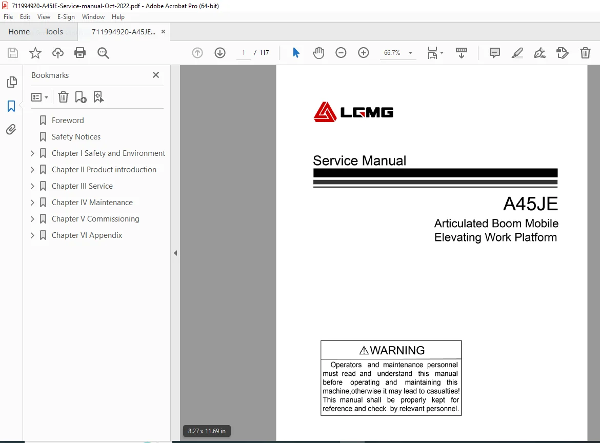
Complete factory service manual for Lingong A45JE (A1408JDTAE30) articulated boom mobile elevating work platform. This 117-page technical manual covers assembly procedures, hydraulic systems, electrical diagnostics, maintenance schedules, and commissioning tests. Includes detailed torque specifications, component removal/replacement procedures, bleeding instructions, and troubleshooting guides for 45-foot working height boom lift with 230kg capacity platform
Description
Lingong A45JE A14JE Service Manual Articulated Boom Lift Repair PDF DOWNLOAD
DESCRIPTION
Lingong A45JE (A14JE) Complete Service Manual – Articulated Boom Mobile Elevating Work Platform
This comprehensive Lingong A45JE service manual provides complete factory technical documentation for servicing and maintaining the A45JE (also known as A14JE, model A1408JDTAE30) articulated boom mobile elevating work platform. Published in October 2022 by Lingong Heavy Machinery Co., Ltd., this professional 117-page manual contains everything technicians need to assemble, diagnose, maintain, and repair this electric-powered aerial work platform.
FILE DETAILS
- Manual Type: Complete Factory Service Manual
- Models Covered: A45JE / A14JE (A1408JDTAE30)
- Equipment Type: Articulated Boom Mobile Elevating Work Platform
- Manufacturer: Lingong Heavy Machinery Co., Ltd., China
- Publication Date: October 2022 (First Edition)
- Pages: 117 pages
- File Quality: High-quality factory PDF with detailed diagrams and photos
- File Size: 6.59 MB
- Language: English
EQUIPMENT SPECIFICATIONS OVERVIEW
Performance Parameters:
- Rated Load Capacity: 230 kg / 510 lbs
- Maximum Working Height: 15.8 m / 51.8 ft
- Maximum Platform Height: 13.8 m / 45.3 ft
- Maximum Horizontal Reach: 7.81 m / 25.6 ft
- Maximum Span Height: 7.26 m / 23.8 ft
- Maximum Allowed Workers: 2 persons
Machine Specifications:
- Overall Mass: 7,500 kg / 16,535 lbs
- Overall Dimensions (L×W×H): 6660 × 1800 × 1980 mm
- Platform Dimensions: 1830 × 760 mm / 5.9 × 2.6 ft
- Drive Type: Two-wheel drive, front wheel steering
- Tire Specification: 9-14.5
Operating Performance:
- Maximum travel speed (retracted): 4.8 km/h / 3 mph
- Maximum travel speed (lifting): 1 km/h / 0.62 mph
- Maximum braking distance: 1-1.5 m
- Theoretical maximum gradeability: 30%
- Maximum allowable wind speed: 12.5 m/s / 28 mph
- Maximum allowable chassis pour angle: 3°
Cycle Times:
- Boom lifting time: 32-40 seconds
- Boom lowering time: 26-30 seconds
- Articulated boom lifting time: 40-52 seconds
- Articulated boom lowering time: 38-46 seconds
- Boom extension time: 22-28 seconds
- Boom retraction time: 25-28 seconds
- Jib lifting time: 38-50 seconds
- Jib lowering time: 22-28 seconds
- Platform rotation time: 6-12 seconds
- Rotary table rotation (stowed): 95-125 seconds
- Rotary table rotation (extended): 95-125 seconds
COMPREHENSIVE MANUAL CONTENTS
This Lingong articulated boom lift service manual contains detailed technical information organized into 5 major sections:
SECTION 1: SAFETY AND ENVIRONMENT
Terms and Definitions
- Administrator responsibilities and qualifications
- Operator requirements and training
- Qualified personnel specifications
- Safety announcement protocols
Before Maintenance
- Pre-service safety checklist
- Required tools and genuine parts usage
- Step-by-step procedure adherence
- Workplace preparation requirements
Workplace Requirements
- Environmental conditions (humidity < 90% at +25°C)
- Operating temperature range: -20°C to +40°C
- Maximum wind speed: 12.5 m/s / 28 mph
- Prohibited environments (corrosive, flammable, explosive)
- Fire extinguisher placement requirements
- Site cleanliness standards
- Ventilation and lighting requirements
Maintenance and Repair Safety Specifications
Pre-Maintenance Safety Procedures:
- Park on solid, level ground
- Block wheels front and rear
- Cut off power supply
- Set all controls to “off” status
- Lower platform to lowest position
- Release hydraulic pressure
- Install safety supports
Additional Safety Requirements:
- Maintenance personnel training requirements
- Genuine parts replacement policy
- Service bulletin compliance
- Vehicle welding repair procedures
- Special operation certificates
- Welding permit requirements
Battery Maintenance Precautions:
- Battery run-out prevention during storage
- Proper charging time control
- Charging frequency management
- Sun exposure prevention
- Temperature management
- Regular inspection schedules
Intended Purpose and Compliance
- Proper use specifications
- Regulatory compliance information
- Equipment description
SECTION 2: PRODUCT INTRODUCTION
A45JE (A1408JDTAE30) Machine Parameters
Complete Performance Specifications:
- Rated load and worker capacity
- Working height and platform height specifications
- Horizontal reach and span height
- Turning radius (inner wheel: 1.83 m, outer wheel: 4.1 m)
- Travel speeds at various configurations
- Gradeability specifications
- Wind speed limitations
- Manual force requirements (400N maximum)
Main Dimensions:
- Overall length: 6660 mm / 21.9 ft
- Overall width: 1800 mm / 5.9 ft
- Overall height: 1980 mm / 6.5 ft
- Wheelbase: 1559 mm / 61 in
- Wheel track: 2030 mm / 80 in
- Minimum ground clearance (middle): 240 mm / 0.79 ft
- Platform dimensions: 1830 × 760 mm
Transmission System:
- Walking reducer rated output torque: 2825 N•m
- Walking reducer speed ratio: 64.08:1
- Slewing reducer rated output torque: 820 N•m
- Slewing reducer speed ratio: 1:1
Hydraulic System Specifications:
- Functional system types
- Pump displacement specifications
- Lifting system maximum working pressure
- System component specifications
Lift Platform Torque Specifications:
- Complete torque specification tables
- Fastener grades and torque requirements
- Assembly torque values for all major components
Key Component Moment Table:
- Detailed torque specifications for critical assemblies
- Bolt and nut torque requirements
- Special fastener specifications
SECTION 3: SERVICE PROCEDURES
3.1 Platform Assembly – Complete Procedures:
File Box Assembly:
- Clip release and opening procedures
- Bolt installation with torque specifications (12±1 N•m)
- Mounting position alignment
Platform Tool Box Assembly:
- Screw installation procedures
- Reference tightening torque: 4 N•m
- Component positioning
Foot Switch Assembly:
- Bottom platform frame mounting
- Screw, nut, and washer installation
- Tool requirements: Allen wrench M4
Lifting Cross Bar Assembly:
- U-bolt and rubber hose installation
- Front door fence mounting
- Side door fence assembly
- Reference tightening torque: 12±1 N•m
- Tools: Open-end wrench 13-16
Protective Mount Assembly:
- Top-to-bottom bolt installation
- Protective mount orientation (opening towards inside)
- Foot mat installation
- Reference tightening torque: 52±5 N•m
Arc Shield Assembly:
- Spacer press-fit procedures
- Double-end stud connection
- Inner and outer side tightening
- Handle orientation requirements
- Smooth rotation verification
- Reference tightening torque: 15±1 N•m
Platform Assembly Installation:
- Platform frame assembly lifting procedures
- Platform support positioning
- U-bolt and base plate fixing
- Multiple torque specifications (15±1, 24±2, 52±5 N•m)
- Tool requirements: Ratchet torque wrench, socket wrench
Load Cell Assembly:
- Load cell positioning and installation
- Electrical connection procedures
- Calibration requirements
Stop Block Assembly:
- Stop block positioning
- Fastener installation
Swing Motor Mounting Bracket:
- Bracket installation procedures
- Motor alignment specifications
Platform Control Unit (PCU) Assembly:
- PCU mounting procedures
- Electrical connections
- Wire routing and protection
Anti-Collision Rubber Pad:
- Pad positioning and installation
- Proper orientation verification
Complete Platform Assembly:
- Final platform assembly procedures
- Alignment verification
- Functional testing
3.2 Axle Assembly:
Front Axle Assembly Removal:
- Support and lifting procedures
- Disconnection sequence
- Component removal steps
Rear Axle Assembly Removal:
- Rear axle support procedures
- Disconnection and removal
Wheel Removal and Installation:
- Wheel bolt loosening sequence
- Removal procedures
- Installation and torque specifications
- Proper tightening sequence
Motor Removal:
- Drive motor disconnection
- Removal procedures
- Electrical connector handling
Reducer Assembly Removal:
- Reducer disconnection
- Removal procedures
- Oil drainage requirements
3.3 Jib Assembly:
Swing Cylinder Removal:
- Pin removal procedures
- Hydraulic line disconnection
- Cylinder extraction
Jib Assembly Removal:
- Support requirements
- Pin and fastener removal
- Complete jib removal procedures
Fly Jib Cylinder Removal:
- Cylinder pin removal
- Hydraulic disconnection
- Cylinder extraction
Swing Cylinder, Fly Jib Cylinder and Jib Assembly:
- Complete assembly procedures with detailed steps
- Alignment specifications
- Pin installation and securing
- Hydraulic connection procedures
- System testing requirements
3.4 Cable Carrier Assembly:
Cable Carrier Removal:
- Fastener removal sequence
- Electrical disconnection
- Carrier extraction procedures
Cable Carrier Installation:
- Positioning and alignment
- Fastener installation sequence
- Cable routing and securing
- Electrical reconnection
3.5 Boom Assembly:
Boom Assembly Removal:
- Support and stabilization procedures
- Pin and fastener removal sequence
- Hydraulic line disconnection
- Complete boom removal
Boom Assembly Installation:
- Positioning and alignment procedures
- Pin installation sequence
- Hydraulic reconnection
- Torque specifications
- Functional verification
Boom Assembly Subassembly:
- Individual component service
- Wear bushing replacement
- Lubrication point service
3.6 Hydraulic Tank:
Hydraulic Tank Installation:
- Tank positioning procedures
- Mounting bracket installation
- Line connection sequences
Hydraulic Tank Removal:
- Oil drainage procedures
- Line disconnection sequence
- Tank extraction and handling
3.7 Cylinder Assembly:
Boom Luffing Cylinder:
- Removal Procedures:
- Pin removal sequence
- Hydraulic line disconnection
- Cylinder extraction
- Installation Procedures:
- Cylinder positioning
- Pin installation and securing
- Hydraulic reconnection
- Bleeding procedures
Boom Telescopic Cylinder:
- Removal procedures with safety precautions
- Support requirements
- Hydraulic system depressurization
Lower Leveling Cylinder:
- Removal Procedures:
- Support installation
- Pin removal
- Cylinder extraction
- Installation Procedures:
- Alignment and positioning
- Pin installation
- System reconnection
Leveling Cylinder:
- Removal and installation procedures
- Alignment verification
- Operational testing
3.8 Articulated Boom Assembly:
Articulated Boom Assembly Removal:
- Support structure installation
- Pin and fastener removal sequence
- Hydraulic disconnection
- Complete assembly extraction
Articulated Boom Assembly Installation:
- Positioning and alignment procedures
- Pin installation sequence
- Hydraulic reconnection
- Torque verification
- Functional testing
Articulated Boom Lift Cylinder:
- Removal Procedures:
- Cylinder support
- Pin extraction
- Hydraulic line disconnection
- Installation Procedures:
- Cylinder positioning
- Pin installation and securing
- Hydraulic system connection
- Bleeding procedures
3.9 Rotary Table Swing Assembly:
Slewing Drive Assembly:
- Removal Procedures:
- Bolt removal sequence
- Gear mesh disengagement
- Assembly extraction
- Installation Procedures:
- Gear alignment
- Bolt installation and torquing
- Lubrication application
- Rotation testing
Lowering the Rotary Table:
- Safe lowering procedures
- Support requirements
- Alignment verification
3.10 Other Components:
Battery Assembly:
- Battery positioning and mounting
- Electrical connection procedures
- Terminal protection
- Securing procedures
Horn Assembly:
- Horn mounting location
- Electrical connections
- Functional testing
Ground Control Unit (GCU) Assembly:
- GCU mounting procedures
- Control panel installation
- Electrical wiring
- System integration
3.11 Valve Group:
Installing the Spool:
- Spool installation procedures
- O-ring positioning
- Torque adjustment specifications
- Leak testing
Boom Function Valve Block:
- Valve block component identification
- Service procedures
- Pressure adjustment
- Flow control settings
3.12 Bleeding Procedures – Complete System:
Function Pump Bleeding:
- Bleeding sequence
- Air removal procedures
- Pressure verification
Slewing Motor Bleeding:
- Motor bleeding procedures
- Rotation verification
Driving Motor Bleeding:
- Drive motor bleeding sequence
- Operational testing
Steering Cylinder Bleeding:
- Cylinder extension and retraction bleeding
- Lock-to-lock steering operation
- Air elimination verification
Folding Jib Luffing Cylinder:
- Cylinder bleeding procedures
- Full stroke operation
- Air removal verification
Main Boom Luffing Cylinder and Lower Leveling Cylinder:
- Combined bleeding procedures
- Sequential operation
- System pressure verification
Main Boom Telescopic Cylinder:
- Extension and retraction bleeding
- Full stroke cycling
- Air elimination
Fly Jib Luffing Cylinder and Upper Leveling Cylinder:
- Bleeding sequence
- Coordinated operation
- System verification
Platform Swing Cylinder:
- Rotation bleeding procedures
- Full rotation cycle
- Smooth operation verification
SECTION 4: MAINTENANCE
4.1 Compliance and Obedience:
- Regulatory compliance requirements
- Service bulletin adherence
- Safety manual compliance
4.2 Checking the Safety Manual:
- Manual availability verification
- Content review requirements
- Update procedures
4.3 Check Labels and Signs:
- Safety label inspection
- Warning sign verification
- Label replacement procedures
4.4 Check for Damaged, Loose or Missing Parts:
- Visual inspection procedures
- Component integrity verification
- Fastener tightness checks
- Missing parts identification
4.5 Check Hydraulic Oil Level and Leakage:
- Oil level verification procedures
- Leak detection and inspection points
- Proper oil level specifications
- Leak repair procedures
4.6 Check the Pivoting Support:
- Slewing bearing inspection
- Bolt torque verification
- Lubrication application
- Wear assessment
4.7 Checking the Battery:
- Electrolyte level verification
- Terminal condition inspection
- Charge level assessment
- Connection tightness verification
- Corrosion inspection
4.8 Check the Wires:
- Wire harness inspection
- Connector integrity verification
- Insulation condition assessment
- Proper routing verification
- Chafing and damage inspection
4.9 Check the Electrical Contactors:
- Contactor operation verification
- Contact condition inspection
- Arc suppression verification
- Connection tightness
4.10 Check Tires and Wheels:
- Tire pressure verification
- Tread depth measurement
- Sidewall condition inspection
- Wheel bolt torque verification
- Rim damage inspection
4.11 Check Drive Hub Oil Level:
- Oil level inspection procedures
- Proper fill level specifications
- Leak detection
- Oil condition assessment
4.12 Check Exhaust Cover of Hydraulic Oil Tank:
- Breather inspection
- Filter element condition
- Cleaning or replacement procedures
- Proper installation verification
4.13 Visual Inspection of Hydraulic Oil:
- Oil color assessment
- Contamination detection
- Viscosity observation
- Replacement criteria
4.14 Platform Weighing Structure Lubrication:
- Load cell lubrication points
- Proper lubricant specification
- Application procedures
- Movement verification
4.15 Checking the Hydraulic Filter:
- Filter element inspection
- Restriction indicator monitoring
- Filter housing inspection
- Replacement procedures
4.16 Replace the Reducer Gear Oil:
- Oil drainage procedures
- Flushing procedures (if required)
- Proper oil specification
- Refill procedures and level verification
4.17 Replace the Air Cleaner:
- Air cleaner removal
- Element inspection
- Replacement procedures
- Proper installation verification
4.18 Replace Hydraulic Oil and Filter:
- Complete oil drainage procedures
- Tank cleaning procedures
- Filter replacement
- Proper oil specification
- Refill and air bleeding procedures
4.19 Regular Maintenance:
- Scheduled maintenance intervals
- Maintenance task checklists
- Record keeping requirements
4.20 Fault Code of Li-Battery:
- Battery management system error codes
- Diagnostic procedures
- Troubleshooting steps
- Resolution procedures
- Complete fault code tables
4.21 Routine Inspection and Maintenance Intervals:
- Daily inspection checklist
- Weekly maintenance tasks
- Monthly service requirements
- Quarterly inspections
- Annual major service procedures
- Hour-based maintenance schedules
SECTION 5: COMMISSIONING
5.1 Safety Instructions:
- Pre-commissioning safety checks
- Personnel qualification requirements
- Safety equipment requirements
- Emergency procedure review
5.2 Machine Inspection:
- Pre-commissioning inspection checklist
- Component verification
- System integrity checks
- Documentation review
5.3 Basic Tests:
Start Test:
- Battery voltage verification
- System power-up sequence
- Control system initialization
- Error code checking
Emergency Stop Switch:
- E-stop function testing
- All control station verification
- System shutdown verification
- Reset procedure testing
Horn Switch:
- Audible warning testing
- Horn operation from all control stations
- Volume verification
Basic Operation Test – Ground Control Unit:
- Control function verification
- Boom movement testing
- Platform rotation testing
- Drive function testing
- All control combinations
Basic Operation Test – Platform Control Unit:
- Platform control verification
- Emergency lowering testing
- Platform rotation from PCU
- All safety interlocks
- Override function testing
Hydraulic Oil Level Test:
- Oil level verification at various boom positions
- Proper level determination
- Refill procedures if required
Travel Speed (High Speed) Test:
- Maximum travel speed measurement
- Speed consistency verification
- Forward and reverse testing
Braking Distance Test:
- Braking distance measurement
- Maximum speed braking
- Repeated testing verification
- Brake performance assessment
Lifting Height Test:
- Maximum working height measurement
- Laser range finder usage
- Platform height verification
- Measurement accuracy: ±1% tolerance
- Height display verification
Additional Commissioning Tests:
- Load capacity testing
- Stability testing
- Control response verification
- Safety system verification
- Environmental limit testing
- Cycle time verification
- All functions under load
KEY FEATURES OF THIS SERVICE MANUAL
✓ Factory Original Documentation – Official Lingong Heavy Machinery technical manual
✓ 117 Comprehensive Pages – Complete service and maintenance coverage
✓ Detailed Assembly Procedures – Step-by-step with torque specifications
✓ Complete Bleeding Instructions – All hydraulic cylinders and motors
✓ Extensive Torque Tables – Component-specific torque specifications
✓ Maintenance Schedules – Routine inspection and service intervals
✓ Li-Battery Fault Codes – Complete diagnostic code tables
✓ Commissioning Procedures – Complete testing and verification protocols
✓ Safety Emphasis – Comprehensive safety procedures throughout
✓ Illustrated Procedures – Detailed photos and diagrams
WHO NEEDS THIS MANUAL?
- Aerial Work Platform Technicians servicing boom lifts
- Rental Equipment Maintenance Departments maintaining AWP fleets
- Heavy Equipment Repair Shops specializing in aerial platforms
- Lingong Authorized Service Centers requiring factory documentation
- Fleet Managers overseeing equipment maintenance programs
- Safety Inspectors performing equipment certifications
- Technical Training Institutions teaching AWP service procedures
SYSTEMS COVERED
This Lingong A45JE boom lift repair manual provides complete service information for:
- Articulated boom hydraulic system
- Electric drive system (battery-powered)
- Platform control unit (PCU)
- Ground control unit (GCU)
- Load weighing system
- Slewing drive assembly
- Hydraulic cylinders (luffing, telescoping, leveling, swing)
- Two-wheel drive transmission
- Front wheel steering system
- Wet disc brake system
- Platform rotation system
- Emergency lowering system
- Safety interlock systems
- Li-battery management system
This Lingong A45JE service manual PDF provides the same technical information used by authorized Lingong service centers worldwide. Essential for anyone maintaining, diagnosing, or repairing these articulated boom aerial work platforms. Download immediately after purchase for instant access to complete service procedures, torque specifications, bleeding instructions, and commissioning test protocols for this 45-foot electric boom lift.