Trusted Business
Verified & Licensed
Virus Free Files
100% Safe Downloads
Secure Payment
SSL Protected
Instant Delivery
Available Immediately
Link-Belt 350X4 Excavator SERVICE MANUAL WLSM3507-03LX – PDF DOWNLOAD
$28.95
Link-Belt 350X4 Excavator SERVICE MANUAL WLSM3507-03LX – PDF DOWNLOAD
Instant PDF Download
Available immediately
Save to Your Device
Download & keep forever
Antivirus Scanned
100% virus-free
Trusted Worldwide
175,000+ customers
Description
Link-Belt 350X4 Excavator SERVICE MANUAL WLSM3507-03LX – PDF DOWNLOAD
FILE DETAILS:
Link-Belt 350X4 Excavator SERVICE MANUAL WLSM3507-03LX – PDF DOWNLOAD
Language : English
Pages :1871
Downloadable : Yes
File Type : PDF
IMAGES PREVIEW OF THE MANUAL:
DESCRIPTION:
Link-Belt 350X4 Excavator SERVICE MANUAL WLSM3507-03LX – PDF DOWNLOAD
General Information
- Cleaning Clean the metal parts with cleaning solution that meets the standard and steam cleaning. (except for bearings) After cleaning, dry well, and inject oil in all parts. Also inject oil into the bearings after drying. Inspection When disassembling parts, check all the parts.
- If there are any worn or damaged parts, replace them. Inspect carefully to prevent initial breakdowns. Bearing Replace any loose bearings. Air dry bearings before installing them. Needle bearing When inserting needle bearings, be very careful not to damage them.
- Apply grease to the section where the needle bearing will be inserted. Gear Check that there is no wear and no damage. Oil seal, O-ring, gasket Always install new oil seals, O-rings, and gaskets. Apply grease to sections where oil seals and O-rings will be inserted.
- Shaft Check that there is no wear and no damage. Check the bearings and check for damaged oil seals on the shaft. Service parts Install LBX Link-Belt genuine service parts. When placing an order, check the parts catalog. It contains the LBX Link-Belt genuine part numbers.
- Any breakdowns arising from the installation of non-genuine parts are not covered by the warranty. Lubricants (fuel, hydraulic oil) Use the oil from the specified company or specified in the operator’s manual or service manual. Any breakdowns arising from any fuel or hydraulic oil other than those specified are not covered by the warranty.
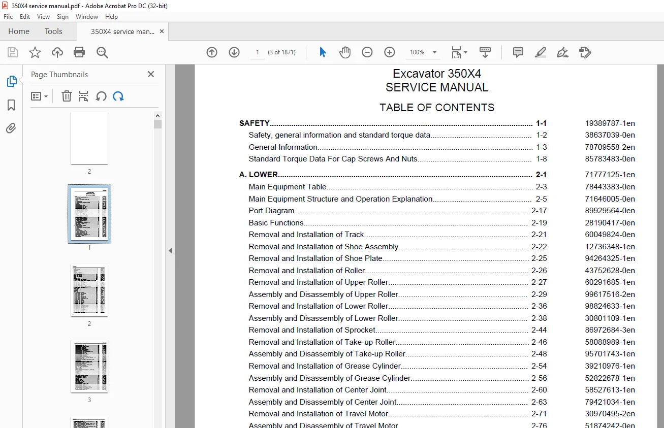
TABLE OF CONTENTS:
Link-Belt 350X4 Excavator SERVICE MANUAL WLSM3507-03LX – PDF DOWNLOAD
Excavator 1
SAFETY 9
Safety, general information and standard torque data 12
General Information 13
Safety 13
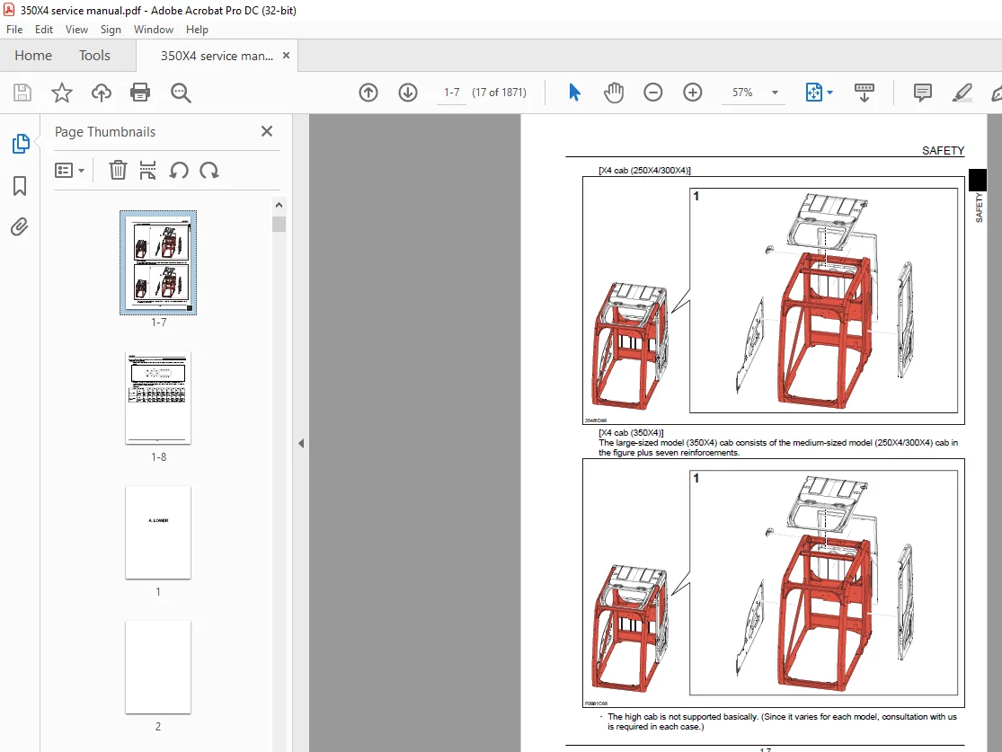
ROPS 15
ROPS Judgment 15
Standard Torque Data For Cap Screws And Nuts 18
Bolt and Nut Tightening 18
A LOWER 19
Main Equipment Table 23
Lower Component 23
Travel Unit 23
Take-up Roller 23
Upper Roller 23
Lower Roller 23
Recoil Spring 23
Shoes 23
Center joint 24
Main Equipment Structure and Operation Explanation 25
Travel Motor 25
Travel motor operation explanation 25
Structure 25
Summary explanation of component parts 26
Rotary group 26
Parking Brake 26
Variable Capacity Mechanism Section 26
Overload Relief Valve 27
Brake Valve Section 27
Function 28
Motor operation 29
Parking Brake Operation 30
Operation of Variable Capacity Mechanism Section 31
Overload Relief Valve Operation 32
Brake Valve Operation 33
Port Diagram 37
Travel Motor 37
Center Joint 38
Basic Functions 39
Travel Speed Selection 39
Travel Alarm 40
Removal and Installation of Track 41
Removal and Installation of Shoe Assembly 42
Removal of Shoe Assembly 42
Installation of Shoe Assembly 43
Removal and Installation of Shoe Plate 45
Removal of Shoe Plate 45
Installation of Shoe Plate 45
Removal and Installation of Roller 46
Removal and Installation of Upper Roller 47
Removal of Upper Roller 47
Installation of Upper Roller 47
Assembly and Disassembly of Upper Roller 49
Configuration Diagram 49
Dimension Diagram 50
Jig Dimension Diagram 50
Disassembly Procedure 50
Assembly Procedures 52
Removal and Installation of Lower Roller 56
Removal of Lower Roller 56
Installation of Lower Roller 57
Assembly and Disassembly of Lower Roller 58
Configuration Diagram 58
Dimension Diagram 59
Jig Dimension Diagram 59
Disassembly Procedures 59
Assembly Procedures 62
Removal and Installation of Sprocket 64
Removal of Drive Sprocket 64
Installation of Drive Sprocket 65
Removal and Installation of Take-up Roller 66
Removal of Take-up Roller 66
Installation of Take-up Roller 66
Assembly and Disassembly of Take-up Roller 68
Configuration Diagram 68
Dimension Diagram 69
Jig Dimension Diagram 69
Disassembly Procedures 69
Assembly Procedures 71
Removal and Installation of Grease Cylinder 74
Removal of Grease Cylinder 74
Installation of Grease Cylinder 75
Assembly and Disassembly of Grease Cylinder 76
Configuration Diagram 76
Dimension Diagram 76
Jig Dimension Diagram 77
Disassembly Procedures 77
Assembly Procedures 78
Removal and Installation of Center Joint 80
Removal of Center Joint 80
Installation of Center Joint 82
Assembly and Disassembly of Center Joint 83
Configuration Diagram 84
Dimension Diagram 85
Jig Dimension Diagram 86
Disassembly Procedures 86
Assembly Procedures 87
Removal and Installation of Travel Motor 91
Removal of Travel Motor 91
Installation of Travel Motor 93
Assembly and Disassembly of Travel Motor 96
Tools for Assembly and Disassembly 96
Standard tools 96
Secondary Materials 96
Special Tool (jig) 97
Measurement Device 100
Motor Disassembly Procedures 100
Precautions before Motor Disassembly 100
Tightening Torque 101
Disassembly Procedure 101
Removal of Supplied Valves 101
Disassembly of Motor 102
Disassembly of Overload Relief Valve 105
Reduction Gear Disassembly Procedures 105
Preparation before Disassembly 105
Disassembly Procedure 105
Installation to Receiving Platform of Reduction Gear (unit) 106
Removal of Reduction Gear Cover 106
Removal of Carrier 1 Assembly 106
Removal of Carrier 2 Assembly 107
Removal of Housing Assembly 107
Disassembly of Housing Assembly 108
Removal of Floating Seal on Motor 109
Disassembly of Carrier 1 Assembly 109
Disassembly of Carrier 2 Assembly 110
Maintenance standards 111
Motor Parts Maintenance Standards 111
Reduction gear parts maintenance standards 113
Inspection before Assembly 113
Thrust Washer 113
Gears 113
Bearing 113
Floating Seal 113
Parts Maintenance 114
Motor Assembly Procedures 115
Precautions before Motor Assembly 115
Assembly Procedure 115
Motor Assembly Procedures 115
Reduction Gear Assembly Procedure 119
Assembly of Carrier 2 Assembly 119
Assembly of Carrier 1 Assembly 119
Installation of Bearing and Floating Seal 120
Assembly of Housing Assembly 120
Determining Thickness of Angular Bearing Shim 121
Installation of Housing Assembly 122
Installation of Carrier 2 Assembly 122
Installation of Carrier 1 Assembly 123
Cover Attachment 124
Gear Oil Filling 124
Initial pre-conditioning operation 124
Drain charge 124
Performing initial operation (pre-conditioning operation) 124
Troubleshooting 125
General cautions 126
Causes of troubles and countermeasures 127
Structural Diagram 129
Internal Structure Diagram 132
Part Table 134
Maintenance Standards 135
Drive Sprocket 135
Take-up Roller 136
Upper Roller 137
Lower Roller 138
Track Shoe (grouser shoe) 139
Inspection Gauge 140
For Drive Sprocket 140
For Take-up Roller 141
For Upper Roller 141
For Lower Roller 142
Pressure Measurement and Adjustment Procedures 143
Main Pressure Measurement 143
B Travel Pressure Measurement 143
Drain Volume Measurement Procedures 144
Preparations 144
Travel Motor Drain Volume Measurement 144
Air Bleed Procedure 146
Travel Motor 146
B C SWING UNIT, COUNTERWEIGHT 149
Main Equipment Table 152
Upper Component 152
Swing Unit 152
Main Equipment Structure and Operation Explanation 153
Swing Motor 153
Swing Motor Operation Explanation 153
Hydraulic Motor Section 153
Valve Casing Section 154
Brake Section 155
Relief Valve Operation Explanation (relief valve model: KRD22EK10) 155
Swing Motor Internal Structure Diagram 158
Port Diagram 161
Swing Motor 161
Basic Functions 162
Swing Brake 162
Swing Lock 162
Swing Speed Limit 164
Swing Relief Cut 165
Removal and Installation of Swing Unit 167
Removal of Swing Unit 167
Installation of Swing Unit 169
Assembly and Disassembly of Swing Unit 170
Disassembly 170
Assembly 171
Assembly and Disassembly of Swing Motor 173
Causes of Trouble and Solutions 173
Maintenance Standard Table 175
Jig 177
Disassembly 177
Assembly 179
Swing Motor Internal Structural Diagram 184
Removal and Installation of Counterweight 187
Removal of Counterweight 187
Installation of Counterweight 188
Pressure Measurement and Adjustment Procedures 189
Main Pressure Measurement 189
C Swing Pressure Measurement 189
Drain Volume Measurement Procedures 190
Preparations 190
Swing Motor Drain Volume Measurement 190
Air Bleed Procedure 191
Swing Motor 191
Check 192
H ENGINE 193
Main Equipment Table 201
Engine-related 201
Engine 201
Air Cleaner (double element) 201
Radiator 201
SCR 202
Basic Functions 203
Fuel Gauge 203
Coolant Temperature Gauge 205
SCR Gauge 206
Fuel Economy Gauge 208
Neutral Start 208
Power-cut Delay 209
Preheat 210
Throttle 211
Throttle Volume Position Detection 211
Idling Start 217
Auto Idle 218
One-touch Idle 219
Auto Warm Up 219
Idle Shutdown 222
Idle Up 223
Work Mode Control 224
Engine Emergency Stop 225
SCR regeneration 225
Inducement 229
Feed Pump Automatic Stop 233
Coolant Level Decrease 235
Air Filter Clogging 236
Fuel Filter Clogging 237
Battery Charge Abnormality 238
Main Data 240
Function, Structure, Operation 243
Function, structure, operation (SCR) 296
SCR Control System Inspection 322
Operation Explanation of SCR 323
Diagnosis for Each Symptom 325
Intermittent conditions of urea selective catalytic reduction system 325
Urea fluid consumption too high 328
Ammonia smell noticeable 328
White crystalline powder visible 329
Symptom 330
Engine Start Problem 330
Engine Stalling 332
Engine Hunting, Rough Idling 334
Excessive White Smoke in Exhaust Gas 335
Excessive Black Smoke in Exhaust Gas 336
Abnormal Noise 336
High Fuel Consumption 337
High Oil Consumption 338
Engine Output Deficiency 339
Functional Inspection 341
Engine Compression Pressure Inspection 341
Fuel System Inspection 342
Lubrication System Inspection 342
Suction air system inspection 343
Exhaust System Inspection 343
EGR Control System Inspection 343
Start System Inspection 344
Glow Control System Inspection 344
OBD System Inspection 345
Monitor Warning Light Lighting Circuit System Inspection 346
Inspection of the monitor warning light blinking circuit system 347
Start Circuit System Inspection 347
Removal and Installation of Engine Assembly 349
Removal of Engine Assembly 349
Installation of Engine Assembly 351
Removal and Installation of Fuel Cooler, Engine Intercooler, Radiator, and Oil Cooler 352
Removal and Installation of Fuel Cooler 352
Removal of Fuel Cooler 352
Installation of Fuel Cooler 352
Removal and Installation of Engine Intercooler 352
Removal of Intercooler 353
Installation of Inter Cooler 353
Inspection of Intercooler 353
Removal and Installation of Radiator 354
Removal of Radiator 354
Installation of Radiator 357
Inspection of Radiator 357
Removal and Installation of Oil Cooler 358
Removal of Oil Cooler 358
Installation of oil cooler 360
Removal and Installation of Turbo Charger 361
Removal of Turbo Charger 361
Installation of Turbo Charger 362
Inspection of Turbo Charger 364
Removal and Installation of EGR Valve 366
Removal of EGR Valve 366
Installation of EGR Valve 367
Inspection of EGR Valve 371
Removal and Installation of Engine Hood 373
Removal of Engine Hood 373
Installation of Engine Hood 373
Removal and Installation of SCR 374
Removal of SCR 374
Installation of SCR 374
Removal and installation of Silicon Controlled Rectifier Catalyst 375
Removal of Silicon Controlled Rectifier Catalyst 375
Installation of Silicon Controlled Rectifier Catalyst 375
Disassembly of Silicon Controlled Rectifier Catalyst 375
Assembly of Silicon Controlled Rectifier Catalyst 375
Inspection of Silicon Controlled Rectifier Catalyst 376
Removal and Installation of Cylinder Head Cover 377
Cylinder head cover Removal 377
Cylinder head cover Installation 377
Removal and Installation of Cylinder Head 378
Removal of Cylinder head assembly 378
Cylinder head assembly Disassembly 387
Cylinder head assembly Reassembly 392
Installation of Cylinder head assembly 400
Cylinder head assembly Inspection 419
Removal and Installation of Cylinder Block 426
Removal of Cylinder block 426
Installation of Cylinder block 442
Cylinder block Inspection 480
Lubrication System 482
Removal and Installation of Oil Pan 482
Oil pan Removal 482
Oil pan Installation 482
Removal and Installation of Oil Level Switch 482
Oil level switch Removal 482
Oil level switch Installation 483
Removal and Installation of Oil Pump Assembly 483
Removal of Oil pump assembly 483
Disassembly of Oil Pump 496
Assembly of Oil Pump 497
Installation of Oil Pump 497
Inspection of Oil Pump 523
Inspection of Engine oil 524
Removal and Installation of Oil Port Cover 525
Removal of Oil port cover 525
Installation of Oil port cover 525
Cooling System 527
Removal and Installation of Water Pump Assembly 527
Removal of Water pump assembly 527
Installation of Water pump assembly 528
Inspection of Water pump assembly 532
Removal and Installation of Thermostat 532
Removal of Thermostat 532
Installation of Thermostat 533
Inspection of Thermostat 535
Coolant Inspection 536
Inspection of Cooling Fan Belt 537
Removal and Installation of Overheat Switch 538
Removal of Overheat switch 538
Installation of Overheat switch 538
Induction System 539
Inspection of Air cleaner element 539
Exhaust System 540
Removal and installation of Oxidation Catalyst Assembly 540
Removal of Oxidation Catalyst Assembly 540
Installation of Oxidation Catalyst Assembly 540
Aux Emission Control Devices System 542
Removal and installation of Dosing Module 542
Removal of Dosing Module 542
Disassembly of Dosing Module 542
Assembly of Dosing Module 543
Installation of Dosing Module 543
Removal and installation of DEF Supply Module 545
Removal of DEF supply module 545
Disassembly of DEF Supply Module 546
Assembly of DEF Supply Module 546
Installation of DEF Supply Module 547
Removal and installation of Coolant Control Valve 549
Removal of Coolant Control Valve 549
Installation of Coolant Control Valve 550
Removal and Installation of DCU 551
Removal of DCU 551
Installation of DCU 552
Removal and installation of DEF Supply Module Filter 552
Removal of DEF Supply Module Filter 552
Installation of DEF Supply Module Filter 552
Removal and Installation of Exhaust Manifold 553
Removal of Exhaust manifold 553
Installation of Exhaust manifold 556
Exhaust manifold Inspection 562
Removal and Installation of Fuel Tank 564
Removal of Fuel Tank 564
Installation of fuel tank 567
Removal and Installation of Urea Pump 568
Removal of Urea Pump 568
Installation of Urea Pump 568
Removal and Installation of Urea Reservoir 569
Removal of Urea Reservoir 569
Installation of Urea Reservoir 570
Removal and Installation of Fuel Supply Pump 571
Removal of Fuel Supply Pump 571
Fuel supply pump Installation 571
Removal and Installation of Common Rail Assembly 575
Removal of Common rail assembly 575
Installation of Common rail assembly 578
Removal and Installation of Injector 588
Injector Removal 588
Injector Installation 590
Removal and installation of Idle Gear 594
Removal of Idle Gear 594
Installation of Idle Gear 606
Inspection of Idle Gear 632
Removal and installation of Inlet Cover 634
Removal of Inlet Cover 634
Installation of Inlet Cover 638
Removal and installation of Crankshaft 647
Removal of Crankshaft 647
Installation of Crankshaft 663
Disassembly of Crankshaft 698
Assembly of Crankshaft 698
Inspection of Crankshaft 699
Removal and installation of Piston 705
Removal of Piston 705
Installation of Piston 715
Disassembly of Piston 736
Assembly of Piston 737
Inspection of Piston 738
Removal and installation of Camshaft 746
Removal of Camshaft 746
Disassembly of Camshaft 747
Installation of Camshaft 748
Assembly of Camshaft 753
Inspection of Camshaft 754
Removal and installation of Flywheel 756
Removal of Flywheel 756
Installation of Flywheel 757
Inspection of Flywheel 758
Removal and installation of Crankshaft Front Oil Seal 759
Removal of Crankshaft Front Oil Seal 759
Installation of Crankshaft Front Oil Seal 760
Removal and installation of Crankshaft Rear Oil Seal 764
Removal of Crankshaft Rear Oil Seal 764
Installation of Crankshaft Rear Oil Seal 765
Removal and installation of Rocker Arm Shaft 768
Removal of Rocker Arm Shaft 768
Installation of Rocker Arm Shaft 769
Disassembly of Rocker Arm Shaft 773
Assembly of Rocker Arm Shaft 773
Inspection of Rocker Arm Shaft 775
Removal and installation of Valve Spring 777
Removal of Valve Spring 777
Installation of Valve Spring 779
Inspection of Valve Spring 785
Removal and installation of Valve Stem Oil Seal 787
Removal of Valve Stem Oil Seal 787
Installation of Valve Stem Oil Seal 789
Removal and installation of Front Cover 797
Removal of Front Cover 797
Installation of Front Cover 799
Removal and installation of Intake Throttle Valve 806
Removal of Intake Throttle Valve 806
Installation of Intake Throttle Valve 806
Removal and Installation of Starter Motor 807
Removal of Starter Motor 807
Installation of Starter Motor 807
Disassembly of Starter Motor 808
Assembly of Starter Motor 809
Inspection of Starter Motor 813
Removal and Installation of Alternator 816
Removal of Alternator 816
Installation of Alternator 816
Disassembly of Alternator 816
Assembly of Alternator 818
Inspection of Alternator 819
Removal and Installation of Glow Plug 823
Removal of Glow Plug 823
Installation of Glow Plug 823
Glow Plug Inspection 824
Removal and Installation of Suction Control Valve 825
Suction control valve Removal 825
Suction control valve Installation 825
Removal and installation of Fuel Filter 828
Removal of Fuel Filter 828
Installation of Fuel Filter 828
Removal and installation of Relief Valve 831
Removal of Relief Valve 831
Installation of Relief Valve 831
Removal and installation of Fuel Filter Element 834
Removal of Fuel Filter Element 834
Installation of Fuel Filter Element 835
Removal and Installation of Fuel filter pressure 838
Suction control valve Removal 838
Suction control valve Installation 838
Removal and Installation of Engine coolant temperature sensor 841
Suction control valve Installation 841
Suction control valve Removal 842
Suction control valve Installation 843
Removal and Installation of CKP sensor 845
Removal of CKP sensor 845
Installation of CKP sensor 845
CKP sensor Inspection 845
Removal and Installation of CMP sensor 846
CMP sensor Removal 846
CMP sensor Installation 846
CMP sensor Inspection 846
Removal and Installation of Oil pressure sensor 847
Removal of Oil pressure sensor 847
Installation of Oil pressure sensor 847
Inspection of Oil pressure sensor 847
Removal and Installation of Boost sensor 848
Removal of Boost Sensor 848
Installation of Boost Sensor 848
Inspection of Boost Sensor 848
Removal and Installation of Boost temperature sensor 849
Removal of Boost Temperature Sensor 849
Installation of Boost Temperature Sensor 849
Removal and installation of Pressure Sensor/Boost Temperature Sensor 850
Removal of Pressure sensor/boost temperature sensor 850
Installation of Pressure sensor/boost temperature sensor 850
Inspection of Pressure sensor/boost temperature sensor 850
Removal and Installation of IMT sensor 851
Removal of IMT sensor 851
Installation of IMT sensor 851
Removal and installation of Charge Air Cooler Temperature Sensor 1 852
Removal of Charge air cooler temperature sensor 1 852
Installation of Charge air cooler temperature sensor 1 852
Inspection of Charge air cooler temperature sensor 1 852
Sampling Procedure 853
Sampling of Engine Oil 853
Removal and Installation of Exhaust gas temperature sensor 854
Removal of Exhaust gas temperature sensor 854
Installation of Exhaust gas temperature sensor 854
Inspection of Exhaust gas temperature sensor 854
Removal and installation of EGR Gas Temperature Sensor 1 856
Removal of EGR Gas Temperature Sensor 1 856
Installation of EGR Gas Temperature Sensor 1 856
Inspection of EGR Gas Temperature Sensor 1 856
Removal and installation of EGR Gas Temperature Sensor 2 857
Removal of EGR Gas Temperature Sensor 2 857
Installation of EGR Gas Temperature Sensor 2 857
Inspection of EGR Gas Temperature Sensor 2 857
Removal and installation of NOx Sensor 859
Removal of NOx Sensor 859
Installation of NOx Sensor 859
Removal and Installation of Exhaust gas temperature sensor 3 860
Removal of Exhaust gas temperature sensor 3 860
Installation of Exhaust gas temperature sensor 3 860
Removal and installation of DEF Sensor 861
Removal of DEF Sensor 861
Installation of DEF Sensor 861
Engine-related Diagnostic Trouble Code List 862
Engine-side Trouble 867
ECM Trouble 867
DTC U0001 CAN Bus Error (ISO-CAN) 867
DTC P0016 Crankshaft Position – Camshaft Position Correlation Error 868
DTC P0045 Turbocharger Boost Control VNT Error 868
DTC U0073 Control Module Communication Bus Off 870
DTC P0087 Fuel Rail/System Pressure – Too Low 871
DTC P0089 Fuel Pressure Regulator Performance 874
DTC P0091 Fuel Pressure Regulator Control Circuit Low 875
DTC P0092 Fuel Pressure Regulator Control Circuit High 876
DTC P0097 Intake Air Temperature (IAT) Sensor 2 Circuit Low Voltage 877
DTC P0098 Intake Air Temperature (IAT) Sensor 2 Circuit High Voltage 877
DTC U0101 Lost Communication With CAN 878
DTC P0102 Mass Air Flow Sensor Circuit Low Input 879
DTC P0103 Mass Air Flow Sensor Circuit High Input 880
DTC U010E Lost Communications With Dosing Control Module 880
DTC U0110 Lost Communication With VNT System 881
DTC P0112 Intake Air Temperature Sensor Circuit Low 881
DTC P0113 Intake Air Temperature Sensor Circuit High 882
DTC P0117 Engine Coolant Temperature Sensor Circuit Low 883
DTC P0118 Engine Coolant Temperature Sensor Circuit High 883
DTC P0122 Throttle Position Sensor Circuit Low 884
DTC P0123 Throttle Position Sensor Circuit High 885
DTC P0182 Fuel Temperature Sensor Circuit Low 886
DTC P0183 Fuel Temperature Sensor Circuit High 887
DTC P0192 Fuel Rail Pressure Sensor Circuit Low 888
DTC P0193 Fuel Rail Pressure Sensor Circuit High 888
DTC P0201 Injector Circuit Open – Cylinder 1 890
DTC P0202 Injector Circuit Open – Cylinder 2 890
DTC P0203 Injector Circuit Open – Cylinder 3 891
DTC P0204 Injector Circuit Open – Cylinder 4 892
DTC P0217 Engine Coolant Over Temperature Condition 893
DTC P0219 Engine Overspeed Condition 893
DTC P0234 Turbocharger Overboost Condition 894
DTC P0237 Turbo Charger Boost Sensor Circuit Low 895
DTC P0238 Turbo Charger Boost Sensor Circuit High 895
DTC P0335 Crankshaft Position Sensor Circuit 896
DTC P0336 Crankshaft Position Sensor Circuit Range/Performance 897
DTC P0340 Camshaft Position Sensor Circuit 898
DTC P0380 Glow Relay Circuit Error 899
DTC P0401 EGR Flow Insufficient Detected 900
DTC P0404 EGR Control Circuit Range/Performance 901
DTC P0409 EGR Sensor Circuit 901
DTC U0411 Lost CAN Communications With VNT Control Module 903
DTC P041C EGR Cooler Outlet 1 Temp Sensor Circuit Low 903
DTC P041D EGR Cooler Outlet 1 Temp Sensor Circuit High 904
DTC P0427 Catalyst Temperature Sensor Circuit Low Sensor 1 905
DTC P0428 Catalyst Temperature Sensor Circuit High Sensor 1 905
DTC P042C Catalyst Temperature Sensor Circuit Low Sensor 2 906
DTC P042D Catalyst Temperature Sensor Circuit High Sensor 2 907
DTC P0522 Engine Oil Pressure Sensor Circuit Low Input 908
DTC P0523 Engine Oil Pressure Sensor Circuit High Input 909
DTC P0545 EGR Cooler Inlet 1 Temp Sensor Circuit Low 910
DTC P0546 EGR Cooler Inlet 1Temp Sensor Circuit High 910
DTC P0560 12 Volt Circuit Error 911
DTC P0563 System Voltage High 911
DTC P0601 Internal Control Module Memory Check Sum Error 912
DTC P0602 Internal Control Module QR Code Error 912
DTC P0604 Internal Control Module RAM Error 913
DTC P0606 Internal Control Module CPU Error 913
DTC P060A Internal Control Module CPU IC Error 913
DTC P060C Internal Control Module A/D Processing Performance 913
DTC P0615 Starter Relay Circuit Error 914
DTC P0638 Throttle Actuator Control Range/Performance 914
DTC P0685 ECM Power Relay Control Circuit Open 915
DTC P0687 ECM Power Relay Control Circuit High 916
DTC P06A6 Sensor Reference Voltage 1 Circuit 916
DTC P06A7 Sensor Reference Voltage 2 Circuit 917
DTC P06A8 Sensor Reference Voltage 3 Circuit 918
DTC P06A9 Sensor Reference Voltage 4 Circuit 918
DTC P06AF Torque Management System – Forced Engine Shutdown 919
DTC P06D5 Sensor Reference Voltage 5 Circuit 920
DTC P1076 Charge Air Cooler (CAC) Temperature Sensor 1 Circuit Low Voltage 920
DTC P1077 Charge Air Cooler (CAC) Temperature Sensor 1 Circuit High Voltage 920
DTC P1093 Fuel Rail Pressure Too Low 921
DTC P1097 Compressor Outlet Temperature Sensor Circuit High 924
DTC P1098 Compressor Outlet Temperature Sensor Circuit High 925
DTC P1236 Charge Air Cooler Performance Failure 926
DTC P1261 Injector Positive Voltage Control Circuit Group 1 926
DTC P1262 Injector Positive Voltage Control Circuit Group 2 927
DTC P1404 EGR Position Fault 927
DTC P1606 SW-IC Internal failure 928
DTC P160B AD-IC Failure Error 928
DTC P160C AD-IC2 Failure Error 928
DTC P1621 Control Module Long Term Memory Performance 928
DTC P1669 DPD Lamp Control Circuit 929
DTC P204F SCR System Error (No Inducement) 930
DTC P207F Urea Fluid Concentration Too Low 930
DTC P20C9 SCR System Error 930
DTC U2106 Lost CAN Communications With Wheel Loader Transmission Control System 930
DTC P2122 Pedal Position Sensor 1 Circuit Low Input 931
DTC P2123 Pedal Position Sensor 1 Circuit High Input 931
DTC P2127 Pedal Position Sensor 2 Circuit Low Input 932
DTC P2128 Pedal Position Sensor 2 Circuit High Input 933
DTC P2138 Pedal Position Sensor 1 – 2 Voltage Correlation 933
DTC P2146 Fuel Injector Group 1 Supply Voltage Circuit 934
DTC P2149 Fuel Injector Group 2 Supply Voltage Circuit 935
DTC P2228 Barometric Pressure Sensor Circuit Low 936
DTC P2229 Barometric Pressure Sensor Circuit High 937
DTC P2457 Exhaust Gas Recirculation (EGR) Cooling System Performance 937
DTC P2458 Purge time Out Error 938
DTC P2BA7 Urea Fluid Quantity Too Low 938
DTC P2BAA SCR System Error (Inducement, No Purge) 938
DTC P3093 Fuel Rail Pressure Too Low 938
DCU Trouble 941
DTC 0002 CAN Bus Off 941
DTC 0100 Lost Communication With ECM 942
DTC 029D Lost Communication With NOx Sensor 1 943
DTC 0607 Control Module Performance 945
DTC 060B Internal Control Module A/D Processing Performance 946
DTC 062F Control Module EEPROM Error 946
DTC 0641 Sensor Reference Voltage 1 Circuit 947
DTC 0658 Actuator Supply Voltage Circuit 948
DTC 0659 Actuator Supply Voltage Circuit 949
DTC 1462 Urea Fluid Quality Sensor Timeout Error 950
DTC 1464 Main Relay Performance 950
DTC 1468 DCU Overtemperature 951
DTC 1491 Urea Fluid Overpressure 951
DTC 1493 DCU Driver Overtemperature 953
DTC 149C Urea Fluid Pressure Reduction Malfunction 953
DTC 149D Urea Fluid Tank Overtemperature 954
DTC 203B Urea Fluid Tank Level Sensor Stuck 955
DTC 203C Urea Fluid Tank Level Sensor Low Voltage 956
DTC 203D Urea Fluid Tank Level Sensor High Voltage 957
DTC 2048 Urea Fluid Injector Circuit Low Voltage 958
DTC 2049 Urea Fluid Injector Circuit High Voltage 959
DTC 204B Urea Fluid Pressure Sensor Performance 959
DTC 204C Urea Fluid Pressure Sensor Circuit Low Voltage 960
DTC 204D Urea Fluid Pressure Sensor Circuit High Voltage 961
DTC 205B Urea Fluid Tank Temperature Sensor Performance 962
DTC 205C Urea Fluid Tank Temperature Sensor Low Voltage 963
DTC 205D Urea Fluid Tank Temperature Sensor High Voltage 963
DTC 206A Urea Fluid Quality Sensor Circuit 964
DTC 206B Urea Sensor Over Temperature Condition 964
DTC 206C Urea Fluid Quality Sensor Circuit Low Voltage 965
DTC 206D Urea Fluid Quality Sensor Circuit High Voltage 966
DTC 207F Urea Fluid Concentration Too Low 966
DTC 208A Urea Fluid Pump Control Circuit 967
DTC 208B Usea Fluid Pump Performance 967
DTC 208C Urea Fluid Pump Control Circuit Low Voltage 968
DTC 208D Urea Fluid Pump Control Circuit High Voltage 969
DTC 208E Urea Fluid Injector Stuck 970
DTC 20A0 Urea Fluid Reverting Valve Circuit Open 971
DTC 20A2 Urea Fluid Reverting Valve Circuit Low Voltage 971
DTC 20A3 Urea Fluid Reverting Valve Circuit High Voltage 972
DTC 20AC Urea Fluid Pump Temperature Sensor Performance 973
DTC 20AD Urea Fluid Pump Module Temperature Sensor Performance 974
DTC 20B1 Urea Fluid Tank Heater Coolant Control Valve Circuit Open 975
DTC 20B3 Urea Fluid Tank Heater Coolant Control Valve Circuit Low Voltage 976
DTC 20B4 Urea Fluid Tank Heater Coolant Control Valve Circuit High Voltage 976
DTC 20E8 Urea Fluid Pressure Underpressure 977
DTC 20E9 Urea Fluid Overpressure 978
DTC 20EA Urea Fluid Pressure Reduction Malfunction 980
DTC 20FE Urea Fluid Pressure Build-Up Error 980
DTC 2201 Upstream Nox Sensor Performance 982
DTC 2206 NOx Sensor Heater Control Circuit Low Voltage Sensor 1 982
DTC 2207 NOx Sensor Heater Control Circuit High Voltage Sensor 1 983
DTC 242B Exhaust Gas Temperature (EGT) Sensor 3 Performance 983
DTC 242C Exhaust Gas Temperature (EGT) Sensor 3 Circuit Low Voltage 983
DTC 242D Exhaust Gas Temperature (EGT) Sensor 3 Circuit High Voltage 984
Data Reference Values 986
Idle Speed 986
Two pump relief 987
J HYDRAULIC EQUIPMENT (PUMP, OPERATION SYSTEM VALVE) 989
Main Equipment Table 995
Hydraulic Device 995
Hydraulic Pump 995
PQ Diagram 995
Control-related 996
Control valve 996
Solenoid Valve (5 Stack) 996
Remote Control Valve for Left/Right Operations 996
Remote Control Valve for Travel Operation 996
Remote Control Valve Characteristic Diagram 997
Operation Remote Control Valve Control Diagram 997
Travel Remote Control Valve Control Diagram 998
Cushion Valve (heat circuit, with shuttle valve) 998
Selector Valve (option) 999
Basic Functions1000
Oil Temperature Gauge1000
Static Horsepower Control1001
Overload Warning (Function for Europe Only)1002
Pressure Boost Control1003
Stroke Control1005
Boom Down Energy Save1006
Pump Horsepower Cut Control1007
Pump Horsepower Boost Control1009
Arm 1 Semi-parallel Control1010
Arm 2 Semi-parallel Control1011
Hot Shutdown Warning1012
Gate Lock1013
Breaker Mode1013
Crusher Mode1014
Quick coupler1015
Hydraulic Filter Clogging1015
Solenoid Sticking Prevention1016
Port Diagram1018
Hydraulic Pump (standard model)1018
Control Valve1020
Relief Valve1020
5 Stack Solenoid Valve1023
2 Stack Solenoid Valve1025
Remote Control Valves (upper, travel)1025
Remote Control Valves (left-right)1025
Remote Control Valve (Travel)1026
Cushion Valve1027
2-way Selector Valve1028
Direction Valve1029
6 Stack Proportional Valve1030
Relief Valve (electromagnetic proportional)1032
Manifold Under Cab1033
Manifold (accumulator section)1034
Manifold (hydraulic oil tank section)1035
Hydraulic Pump1036
Structure and Operation Explanation1036
Hydraulic Pump Internal Structure Diagram1037
Overall view1037
Drive Shaft Front Side1037
Drive Shaft on Rear Side1038
Parts Table1039
Regulator1040
Regulator Operation Explanation1040
Regulator Operation Explanation Diagram1042
Internal Configuration Diagram of Regulator1044
Development Diagram of Regulator1046
Component Table1047
Gear Pump1049
Gear Pump Internal Structure Diagram1049
Structure and Operation Explanation1050
Operation Outline of Electronically-Controlled Pump1051
Control Valve1054
Basic Configuration1054
Operation1054
Operation of Main Unit1054
Activation of Relief Valve1075
5 Stack Solenoid Valve Operation Explanation1080
External Shape Diagram and Components1080
operation explanation1080
Upper Pilot Valve (remote control valve)1081
Structure1081
Function1081
Operation1082
Structural Diagram1086
Travel Pilot Valve (remote control valve)1087
Operation1087
Pressure Reducing Valve Section1087
Damping Mechanism in Operation Section1088
Structural Diagram1091
Cushion Valve 1093
structure1093
operation explanation1093
Selector Valve (2-way)1098
structure1098
operation explanation1099
Development Diagram1100
Direction Valve (3-direction) 1101
Structure1101
Operation Explanation1102
6 Stack Proportional Valve (Pilot)1104
structure1104
operation principle1105
Electromagnetic Relief Valve1106
Structure1106
Operation Explanation1107
Operation of Check Valve1107
Operation of Electromagnetic Relief Valve1108
Removal and Installation of Hydraulic Reservoir1110
Removal of Hydraulic Reservoir1110
Installation of Hydraulic Oil Tank1113
Removal and Installation of Hydraulic Pump1114
Removal of Hydraulic Pump1114
Installation of hydraulic pump1117
Removal and Installation of Control Valve1118
Removal of Control Valve1118
Installation of Control Valve1123
Removal and Installation of Travel Remote Control Valve1124
Removal of Travel Remote Control Valve1124
Installation of Travel Remote Control Valve1125
Removal and Installation of Operation Remote Control Valve1128
Removal of Operation Remote Control Valve (left side)1128
Installation of Operation Remote Control Valve (left side)1130
Removal of Operation Remote Control Valve (right side)1132
Installation of Operation Remote Control Valve (right side)1134
Installation and Removal of 5 Stack Solenoid Valve1136
Removal of 5 Stack Solenoid Valve1136
Installation of 5 Stack Solenoid Valve1137
Removal and Installation of Cushion Valve1138
Removal of Cushion Valve1138
Installation of Cushion Valve1139
Procedures for Assembly and Disassembly of Hydraulic Pump Main Unit1141
Tools1141
Disassembly Procedure1141
Assembly Procedure1143
Regulator Maintenance Standards1146
Regulator Adjustment1146
Appendix Table and Drawings1147
Regulator Assembly and Disassembly Procedures1151
Tools1151
Preparations for Disassembly1151
Disassembly Procedure1151
Assembly Procedure1153
Internal Configuration Diagram of Regulator1157
Development Diagram of Regulator1159
Component Table1160
Assembly and Disassembly of Control Valve1162
Disassembly1162
Caution for Disassembly1162
Disassembly Procedure1162
Removal of Long Cap and Pulling Out of Main Spool1162
Disassembly of Arm 1, 2 Parallel-Tandem Spool, Neutral Cut Spool, Arm Regeneration Release Spool Section1163
Disassembly of Load Check Valve Section1163
Disassembly of Antidrift Valve Section (Sub Component in Assembly is Expressed by (Min Number – Sub Number))1164
Disassembly of Relief Valve1164
Disassembly of Option Section1164
Disassembly of Add-On Section1164
Disassembly of Valve Housing Coalescence Bolt1165
Cleaning1165
Inspection1165
assembly1165
Caution for Assembly1165
Caution for Handling O-ring1165
Caution for Handling Spool1165
Method to Apply Adhesive Agent (Male and Female Thread Section of Components Requiring Bonding)1165
Assembly Procedure of Sub-Assembly1166
Assembly of Spool Assembly (Main Spool)1166
Assembly of Arm 1, 2 Parallel-Tandem Spool, Neutral Cut Spool, Arm Regeneration Release Spool Assembly1166
Assembly of Antidrift Valve Assembly1167
Assembly Procedure of Control Valve Main Unit1167
Assembly of Relief Valve1167
Assembly of Load Check Valve1167
Assembly of Antidrift Valve1168
Assembly of Option Section1168
Assembly of Arm 1 Parallel-Tandem Spool1168
Assembly of Arm 2 Parallel-Tandem Spool, Neutral Cut Spool, Arm Regeneration Release Spool1168
Assembly of Main Spool1168
Assembly of Add-On Section1169
Assembly of Other Plugs1169
Internal Structural Diagram1170
Part List1176
Relief Valve1177
Assembly and Disassembly Procedure of Main Relief Valve1177
Assembly and Disassembly Procedures of Overload Relief1178
Assembly and Disassembly Procedure of Low-Pressure Relief Valve1179
Assembly and Disassembly Procedure of Main Relief Valve for Add-On1179
Adjustment of Relief Valve1180
Installation1181
Operation1181
Malfunction and Countermeasure1181
Procedures for Assembly and Disassembly of Operation Remote Control Valve1183
Maintenance Procedures1183
Required Tools and Tightening Torque1183
Maintenance Standards1183
Disassembly Procedures1184
Assembly Procedures1186
Causes of Trouble and Countermeasures1190
Procedures for Assembly and Disassembly of Travel Remote Control Valve1194
Maintenance Procedures1194
Disassembly Procedures1195
Assembly Procedures1199
Causes of Trouble and Countermeasures1204
Assembly and Disassembly of Cushion Valve1207
Disassembly Procedures1207
Reverse Operation Spool Section1207
Check Plunger Section with Throttle1207
Shuttle Valve Section1207
Assembly Procedures1208
Reverse Operation Spool Section1208
Check Plunger Section with Throttle1208
Shuttle Valve Section1208
Written Materials1209
Procedures for Assembly and Disassembly of 6 Stack Proportional Valve (Pilot)1211
Development Diagram1211
Assembly and disassembly procedures1212
Precautions1212
Replacement of Proportional Solenoid1212
Disassembly1212
Assembly1212
Replacement of Sleeve and Spool1213
Disassembly1213
Assembly1214
Replacement of Poppet (Check Valve for Normally Open)1215
Disassembly1215
assembly1216
Maintenance Standards1216
Troubleshooting1216
Pressure Measurement and Adjustment Procedures1218
Procedures for Pressure Measurement from the Monitor Display1218
Monitor and Switch Panel1218
Pressure Measurement Method1218
Operating Method1218
PROCEDURES FOR MEASURING HYDRAULIC OIL TEMPERATURE FROM THE MONITOR DISPLAY1218
Hydraulic Oil Temperature Measurement Method1218
Operating Method1219
Procedures for Pressure Measurement by Installing Pressure Gauge1220
Preparations1220
Items to Prepare1220
Pressure Measuring Ports1221
Control Valve1223
Location of Relief Valves1223
Pressure Measurement Preparations1224
Pressure Measurement1226
Main Pressure Measurement1226
A Attachment Pressure Measurement1226
Boom-down Pressure Measurement1227
D Option Line Pressure Measurement1228
Pilot Pressure Measurement1228
Pressure Gauge Installation1228
Negative Control Pressure Measurement1229
Pressure Gauge Installation1229
Pressure Adjustment1229
Main Pressure Adjustment1229
Pressure Measurement and Adjustment Preparations1229
Main Relief Pressure Adjustment1231
Overload Relief Pressure Adjustment1232
Swing Relief Pressure Adjustment1233
Pilot Pressure Adjustment1234
Hydraulic Pump Flow Measurement Procedures1235
Preparations1235
Items to Prepare1235
Work Preparations1235
Flow Measurement1237
Air Bleed Procedure1239
Hydraulic Pump1239
Sampling Procedure1240
Sampling of Hydraulic Fluid1240
Hydraulic Equipment Layout1241
Overall View1242
Pump Chamber Hydraulic Equipment Layout1243
Swing Body Center Section Hydraulic Equipment Layout1245
Housing Left Side Hydraulic Equipment Layout1247
Layout of Hydraulic Equipment in Cab1248
N CAB1323
Removal and Installation of Operator’s Seat1326
Removal of Operator’s Seat1326
Installation of Operator’s Seat1326
Removal and Installation of Cab Assembly1327
Removal of Cab Assembly1327
Installation of Cab Assembly1331
Removal and Installation of Wiper1332
Removal of Wiper1332
Installation of wiper1332
Removal and Installation of Cab Front Glass1333
Removal of Cab Front Glass1333
Installation of Cab Front Glass1334
Window Lock Adjustment Procedures1335
Window Lock (front side)1335
Window Lock (rear side)1335
Removal and Installation of Housing Guardrail1337
Removal of Housing Guardrail1337
Installation of Housing Guardrail1338
Tightening Torque1339
R ELECTRICAL PARTS1341
Basic Functions1345
Monitor Control1345
Monitor Display Dimming1345
Diagnostic Trouble Code Indicator1346
Clock1346
Basic Operation1347
Battery Save1347
Accessories1349
Working Light1349
LED Light1350
Room Lamp1351
Radio Mute1352
Wiper and Washer1353
Safety1356
Horn1356
Back/Side View Monitor1357
Precautions for Camera Installation1357
Maintenance1358
Anti-theft1358
Manual Lock1358
Service Support Screen Lock1358
Customer-specific System Information Screen Lock1358
Maintenance Information Screen Lock1359
Option Line Setting Screen Lock1359
Setting1359
Clock Adjustment1359
Screen Brightness Setting1360
Battery Disconnect Switch1361
Explanation of Controller1362
Service Support1364
Screen Operations1364
Screen Display List1364
Service Monitor Structure1365
CHECK Screen List1366
MACHINE STATUS1366
HYDRAULIC STATUS1372
ENGINE STATUS1379
FAULT HISTORY1384
WORK HISTORY1384
HYDRAULIC HISTORY1393
ENGINE HISTORY1405
DEVICE TEST1426
ECM/DCU Memory Clear1426
Urea Line Leak Test1427
CCV Operation Test1428
Dosing Test1429
Reverting Valve Operation Test1430
Common Rail Pressure Test1431
Injector Balance Test1432
Injector Forced Drive Test1433
EGR Valve Control Test1434
VG Turbo Control Test1435
Intake Throttle Control Test1436
CONTROL UNIT Screen List1437
MCM-MAIN1437
MCM-SUB1441
COMMU TERMINAL1442
SETUP Screen List1444
MACHINE SELECT1445
DIMENSIONS1449
PARAMETERS1450
ENGINE INFORMATION1452
ENGINE INFORMATION1453
Data Confirmation1453
Data Transfer (Copy)1454
QR (INJECTOR) CODE1455
Injector number1455
Screen Layout1455
Data Source Selection1455
Manual Input1456
CAMERA1457
PASSWORD1460
CALIBRATE Screen List1463
Throttle Volume1463
OPTLINE RELIEF1464
PUMP FLOW1465
Connection Connector Pin Layout1468
Main Controller1468
Monitor1469
Sequence Circuit Diagram1470
Code List1470
Overall1472
Block diagram1475
Main Controller1475
DCU1476
ECM1477
Monitor1478
Air Conditioner1479
Lever Lock1480
Horn1480
Working Light1480
Option1481
Other1482
Electrical Symbol List1482
Electrical Equipment Layout Diagram1484
Main Unit Left-side Layout Diagram1485
Engine Section Layout Diagram1487
Main Unit Right Side Layout Diagram (pump chamber)1490
Main Unit Center Section Layout Diagram1491
Cab Layout Diagram 11492
Cab Layout Diagram 21494
Layout Around Operator Seat1497
Stand Alone Parts Diagram1498
Removal and Installation of Wiper Controller1520
Removal of Wiper Controller1520
Installation of wiper controller1520
Removal and Installation of Wiper Motor1521
Removal of Wiper Motor1521
Installation of wiper motor1522
Removal and Installation of ECM1523
Removal of ECM1523
Installation of ECM1523
Removal and Installation of Main Controller1524
Removal of Main Controller1524
Installation of Main Controller1524
Removal and Installation of DCU1525
Removal of DCU1525
Installation of DCU1525
Removal and Installation of Monitor1526
Removal of Monitor1526
Installation of Monitor1527
Air Conditioner Overall Diagram1528
Frame1528
Cab1531
Equipment Layout Diagram1534
Circuit Diagram1536
Air Conditioner Circuit Diagram1536
Explanation of Functions1538
Explanation of Control1538
Air Mix Motor Actuator Control1539
Blow Mode Motor Actuator Control1539
Refresh/Recirculate Switch Motor Actuator Control1540
Blower Amp Control1541
Compressor Clutch Control1543
COOLMAX Control and HOTMAX Control1544
Abnormality Detection and Control after Abnormality Detected1544
Monitor Mode1548
Door Switch Control1550
Actuator Inspection1551
Air Mix Motor Actuator Inspection1551
Refresh/Recirculate Switch Motor Actuator Inspection1552
Mode Motor Actuator Inspection1553
Self-diagnosis Function with Panel Display1554
Abnormality Display and Self-check Procedures1554
Abnormality Display Position1554
Explanation of Abnormality Display1554
Motor Actuator Abnormality1554
Sensor Abnormality1555
Explanation of Monitor Mode1555
Monitor Mode Display Position1556
Monitor Mode Display Operating Method1556
Display Contents in Monitor Mode1557
Part Function and Good/Poor Judgment1563
Control Panel1563
Blower Amp1563
Relay1564
Air Mix Actuator1565
Refresh/Recirculate Actuator1566
Blow Mode Actuator1566
Evaporator Sensor1567
Dual Pressure Switch1567
Solar Radiation Sensor1568
Inside Air Sensor1568
Assembly and Disassembly of Unit1570
Removal of Blower Unit1570
Replacement of Blower Motor1570
Replacement of Blower Amp1570
Removal of Heater Core1571
Removal of Heat Case Right/Left1571
Replacement of Evaporator and Expansion Valve1571
Installation of Evaporator Sensor1572
Replacement of Motor Actuator1572
Removal and Installation of Compressor1573
Removal of Compressor1573
Installation of Compressor1573
Removal and Installation of Condenser1574
Removal of Condenser1574
Installation of condenser1574
Removal and Installation of Receiver Dryer1575
Removal of Receiver Dryer1575
Installation of receiver dryer1575
Work Precautions1576
Work Procedures1576
Air Conditioner Refrigerant Filling is Divided into the “Vacuum Operation” and “Gas Filling Operation”1576
Operation Chart1577
Tools1577
Filling Procedures1579
Charging Hose Connection Position1579
Connecting Gauge Manifold1579
Vacuuming1580
Gas Filling Operation, High-pressure Side1581
Gas Filling Work, Low Pressure Side1581
V ATTACHMENTS1615
Main Equipment Table1619
Backhoe Attachment1619
Cylinder1619
Maintenance Standards1620
Attachment (Backhoe)1620
1 Boom and swing frame mounting area1620
2 Boom Cylinder and Swing Frame Installation Section1621
3 Boom and Boom Cylinder Installation Section1622
4 Boom and Arm Cylinder Installation Section1622
5 Boom and Arm Installation Section1623
6 Arm and Arm Cylinder Installation Section 1624
7 Arm and Bucket Cylinder Installation Section1624
8 Arm and Arm Link Installation Section1625
9 Bucket and Bucket Link Installation Section1626
10 Bucket Link and Bucket Cylinder Installation Section1626
11 Bucket and Arm Installation Section1627
Removal and Installation of Bucket Cylinder1629
Removal of Bucket Cylinder1629
Installation of Bucket Cylinder1631
Removal and Installation of Arm Cylinder1633
Removal of Arm Cylinder1633
Installation of Arm Cylinder1635
Removal and Installation of Boom Cylinder1638
Removal of Boom Cylinder1638
Installation of Boom Cylinder1640
Procedures for Operation/Assembly and Disassembly of Hydraulic Cylinder1642
Specifications and Structure Diagram (including the assembly diagram and parts table)1642
Basic Functions1642
Function of Each Location1642
Cylinder Head Assembly (made by KYB)1642
Piston Assembly (made by KYB)1643
Pipe Assembly (made by KYB)1645
Handling Precautions1645
Precautions for Installing the Cylinder on the Machine Body1645
Usage Cautions1646
Maintenance and Inspection Cautions1646
Maintenance Inspection and Service1648
Trouble Diagnostics1649
Storage Standards1654
Storing Parts Individually (In principle, store indoors)1654
When Mounted on Vehicle Body1654
Recommended Anti-rust Oil1654
Assembly and Disassembly Procedures1655
Preparations ····· Prepare the Following before Starting Disassembly1655
General Work Precautions1655
Maintenance Standards1655
Inspection after Assembly1655
Required Tool1656
General Tool1656
Special Jig (made by KYB)1657
Special Jig Parts Number List (made by KYB)1657
Disassembly Procedures (made by KYB)1658
Assembly Procedures (made by KYB)1661
Test Operation1666
Usage Limits1667
Structural Diagram (made by KYB)1668
Boom Cylinder1668
Arm Cylinder1670
Bucket Cylinder1672
HBCV1674
structure1674
Function1674
operation explanation1674
Port Diagram1689
HBCV1689
Air Bleed Procedure1690
HBCV1690
Boom Cylinder HBCV1690
Arm Cylinder HBCV1691
Removal and Installation of HBCV1692
Removal and Installation of Arm HBCV1693
Removal of Arm HBCV1693
Installation of Arm HBCV1693
Removal and Installation of Boom HBCV1695
Removal of Boom HBCV1695
Installation of Boom HBCV1696
Removal and Installation of Bucket1698
Removal of Bucket1698
Installation of Bucket1698
Removal and Installation of Bucket Link1700
Removal of Bucket Link1700
Installation of Bucket Link1700
Removal and Installation of Arm1702
Removal of Arm1702
Installation of Arm1703
Removal and Installation of Boom1704
Removal of Boom1704
Installation of Boom1706
Z OTHER1709
Changes from Model -61714
Overall Layout1714
Lower1714
Swing Unit1715
Engine1715
hydraulic-related1717
Hydraulic Control1718
Cab, Housing1719
Electrical Data1721
Electric Control1722
Attachments1722
Specifications1723
ENGINE1723
HYDRAULIC SYSTEM1723
HYDRAULIC CONTROLS1724
ELECTRICAL SYSTEM1724
OPERATOR ENVIRONMENT1725
UNDERCARRIAGE1726
MASS1726
DIGGING FORCE (with 14 m3 Sumitomo Bucket) (ISO 6015)1726
DIMENSIONS1726
WORKING RANGES1727
SYSTEM FLUID CAPACITIES AND SPECIFICATIONS1727
Main Unit Weight1729
Divided Weight (Standard Specifications)1729
Stand Alone Part Weight1729
Shoe Weight (per side)1730
Arm Weight1730
Bucket Weight1730
Bolt Size and Torque Table1732
Special Torque Setting1732
Overall View1736
350X41736
Standard Arm (325 m (1066 ft))1736
Short Arm (263 m (863 ft))1737
Long Arm (404 m (1325 ft))1738
WORK RANGE DIAGRAM1739
350X41739
Standard Arm (325 m (1066 ft))1739
Short Arm (263 m (863 ft))1741
Long Arm (404 m (1325 ft))1743
FLUIDS AND LUBRICANTS1745
HYDRAULIC FLUID1745
Engine Oil1745
Fuel1745
Conditions applicable to diesel fuel1745
Recommended Conditions Applicable to Diesel Fuel1745
Main-unit-related Diagnostic Trouble Code List1746
Main Unit-side Trouble1749
Diagnostic Trouble Code: 7000 Pressure Sensor P1 Abnormality1749
Diagnostic Trouble Code: 7001 Pressure Sensor P2 Abnormality1750
Diagnostic Trouble Code: 7002 Pressure Sensor N1 Abnormality1752
Diagnostic Trouble Code: 7003 Pressure Sensor N2 Abnormality1753
Diagnostic Trouble Code: 7004 Pressure Sensor Boom Cylinder Bottom Abnormality1755
Diagnostic Trouble Code: 7006 Rod Pressure Sensor Signal Abnormality1756
Diagnostic Trouble Code: 7007 Pressure Sensor Arm Cylinder Rod Abnormality1758
Diagnostic Trouble Code: 7021 Pressure Sensor Swing Pilot Abnormality1759
Diagnostic Trouble Code: 7023 Pressure Sensor Arm-In Pilot Abnormality1761
Diagnostic Trouble Code: 7040 Level Sensor Fuel Abnormality1762
Diagnostic Trouble Code: 7041 Temperature Sensor Hydraulic Fluid Abnormality1763
Diagnostic Trouble Code: 7065 Pressure Sensor Boom-Up Pilot Abnormality1765
Diagnostic Trouble Code: 7067 Pressure Sensor Bucket-Close Pilot Abnormality1766
Diagnostic Trouble Code: 7068 Pressure Sensor Boom-Down Pilot Abnormality1768
Diagnostic Trouble Code: 7069 Pressure Sensor Arm-Out Pilot Abnormality1770
Diagnostic Trouble Code: 7070 Pressure Sensor Bucket-Open Pilot Abnormality1771
Diagnostic Trouble Code: 7071 Pressure Sensor Travel Right Pilot Abnormality1773
Diagnostic Trouble Code: 7072 Pressure Sensor Travel Left Pilot Abnormality1775
Diagnostic Trouble Code: 7073 Pressure Sensor Travel 1 Pedal Abnormality1777
Diagnostic Trouble Code: 7074 Pressure Sensor 1st Option Pilot (Common/Front Pedal) Abnormality1778
Diagnostic Trouble Code: 7075 Pressure Sensor Arm Cylinder Bottom Abnormality1780
Diagnostic Trouble Code: 7078 Pressure Sensor 1st Option Pilot (Rear Pedal) Abnormality1782
Diagnostic Trouble Code: 7200 Swing Brake Solenoid Abnormality1784
Diagnostic Trouble Code: 7201 Travel 2nd-Speed Switchover Solenoid Abnormality1785
Diagnostic Trouble Code: 7202 Pressure Boost Solenoid Abnormality1786
Diagnostic Trouble Code: 7203 Travel Alarm Buzzer Abnormality1787
Diagnostic Trouble Code: 7206 Option Return Line Switchover Solenoid Abnormality1788
Diagnostic Trouble Code: 7207 Free Swing Solenoid Abnormality1789
Diagnostic Trouble Code: 7212 Shut-off Solenoid Signal Abnormality1790
Diagnostic Trouble Code: 7213 Quick Coupler Buzzer Abnormality1791
Diagnostic Trouble Code: 7214 Quick Coupler Solenoid Abnormality1793
Diagnostic Trouble Code: 7247 Boom 2-Down Pilot Proportional Valve Abnormality1795
Diagnostic Trouble Code: 7249 Bucket-Close Pilot Proportional Valve Abnormality1796
Diagnostic Trouble Code: 7250 Option Relief Pressure Proportional Valve Abnormality1797
Diagnostic Trouble Code: 7265 Arm 1 Semi-Parallel Proportional Valve Abnormality1799
Diagnostic Trouble Code: 7266 Arm 2 Semi-Parallel Proportional Valve Abnormality1800
Diagnostic Trouble Code: 7267 Arm 1 Regeneration Release Proportional Valve Abnormality1801
Diagnostic Trouble Code: 7270 Tilting 1 Proportional Valve Abnormality1802
Diagnostic Trouble Code: 7271 Tilting 2 Proportional Valve Abnormality1804
Diagnostic Trouble Code: 7273 Straight Travel Proportional Valve Abnormality1805
Diagnostic Trouble Code: 7400 Coolant Temperature Overheating 11806
Diagnostic Trouble Code: 7401 Coolant Temperature Overheating 21807
Diagnostic Trouble Code: 7404 Oil Temperature Overheating1808
Diagnostic Trouble Code: 7405 Boost Temperature Overheating 11809
Diagnostic Trouble Code: 7406 Boost Temperature Overheating 21810
Diagnostic Trouble Code: 7420 Alternator Power Generation Failure1811
Diagnostic Trouble Code: 7421 Coolant Level Decrease1812
Diagnostic Trouble Code: 7422 Engine Oil Pressure Decrease1813
Diagnostic Trouble Code: 7423 Air Cleaner Clogging1814
Diagnostic Trouble Code: 7424 Return Filter Clogging1815
Diagnostic Trouble Code: 7426 Fuel Filter Clogging 11816
Diagnostic Trouble Code: 7427 Fuel Filter Clogging 21817
Diagnostic Trouble Code: 7428 Inducement (Remaining Urea Level Low) – Warning1818
Diagnostic Trouble Code: 7429 Inducement (Remaining Urea Level Low) – Early1819
Diagnostic Trouble Code: 7430 Inducement (Remaining Urea Level Low) – Final1819
Diagnostic Trouble Code: 7602 ECM Communication Abnormality1820
Diagnostic Trouble Code: 7603 Computer S Communication Abnormality1821
Diagnostic Trouble Code: 7605 ECM Not-Matched1822
Diagnostic Trouble Code: 7606 EEPROM Abnormality1822
Diagnostic Trouble Code: 7608 Camera Abnormality1823
Diagnostic Trouble Code: 7612 Air Conditioner Communication Abnormality1824
Diagnostic Trouble Code: 7613 Monitor Communication (CAN) Abnormality1826
Diagnostic Trouble Code: 7615 Sub-Controller Communication Abnormality1827
Diagnostic Trouble Code: 7618 DCU Communication Abnormality1828
List of special tools1830
NUMERICAL VALUE CONVERSION TABLE1830
Unit conversion rate1830
Length1830
Area1832
Volume1833
Weight1835
Pressure1836
Torque1837
Temperature1838
A1841
Travel Motor Special Tool1841
350X41841
Take-up Roller Special Tool1848
350X41848
Upper Roller Special Tool1849
350X41849
Lower Roller Special Tool1850
350X41850
Grease Cylinder Special Tool1850
350X41850
Center Joint Special Tool1851
350X41851
C1852
Swing Motor Special Tool1852
350X41852
H1854
Engine Oil Filter Special Tool1854
350X41854
Fuel Filter Special Tool1854
350X41854
Injector Special Tool1854
350X41854
Circuit Test Special Tool1855
350X41855
Valve Guide Special Tool1855
350X41855
Cylinder Head Special Tool1855
350X41855
Head Bolt Special Tool1858
350X41858
Crankshaft Special Tool1858
350X41858
Camshaft Special Tool1861
350X41861
Valve Spring Special Tool1861
350X41861
J1862
Remote Control Valve Special Tool1862
350X41862
R1863
Gas Filling Special Tool1863
350X41863
V1864
Attachment Special Tool (for Cylinder Assembly)1864
Special Jigs Part Number List1864
Attachment Special Tool (Other)1865
350X41865
Paint Colors1866
Abbreviation1868
WLSM3507-00LX-A3-Jpdf 0
A3 Assembly Diagrams 0
J1249
Explanation of Hydraulic Circuit and Operations (standard model)1251
Travel Circuit1252
Travel Low-speed Circuit1252
Travel High-speed Circuit1254
Straight Travel Circuit (with HBCV)1256
Swing Circuit1258
Swing Speed Limit Control Circuit1258
Swing Relief Cut Control Circuit1260
Swing Brake Circuit1262
Swing Parking Circuit (lever in neutral)1264
Swing Parking Circuit (brake release)1266
Swing Parking Circuit (machine stop)1268
Boom Circuit1270
Boom-up Circuit (independent operation) (with HBCV)1270
Boom-up Spool Stroke Control Circuit (compound boom-up + arm-in) (with HBCV)1272
Boom-down Regenerative Circuit (with HBCV)1274
Boom-down Tilting Prevention Circuit (with HBCV)1276
Boom-down Load Holding Valve Circuit (with HBCV)1278
Arm Circuit1280
Arm-out Circuit (with HBCV)1280
Arm Semi-Parallel 1 Circuit1282
Arm Semi-Parallel 2 Circuit1284
Arm-in Regenerative Circuit (with HBCV)1286
Arm-in Load Holding Valve Circuit (with HBCV)1288
Bucket Circuit1290
Bucket-open Circuit1290
Bucket-close Regenerative Circuit1292
Bucket-Close Spool Stroke Control Circuit1294
Negative Control Circuit1296
Negative Control Circuit1296
Other Circuits1298
Cushion Circuit (arm-out operation)1298
Cushion Circuit (when arm-out operation stopped)1300
Cushion Circuit (arm-out → arm-in operation)1302
Heat Circuit (lever in neutral)1304
Auto Pressure Boost Circuit (arm in)1306
J1309
Explanation of Hydraulic Circuit and Operations (option)1311
Option Circuits1312
Breaker Circuit (independent operation)1312
Double-acting Circuit (hydraulic fork)1314
Multi-purpose Circuit (breaker Q control)1316
Multi-purpose Circuit (2 pumps flow crusher)1318
2nd Option Circuit (hydraulic rotation fork)1320
R 0
Electrical Connector Wiring Diagram 0
Main Frame 0
Control Valve 0
SCR 0
Cab Main Harness 0
Console 0
EST-A 0
Indicator Jumper 0
R 0
Electrical Parts and Wiring Assembly Diagram 0
Frame 0
Engine and Pump 0
Attachments 0
Battery 0
Cab 0
WLSM3507-00LX-A3-Rpdf 0
A3 Assembly Diagrams 0
J 0
Explanation of Hydraulic Circuit and Operations (standard model) 0
Travel Circuit 0
Travel Low-speed Circuit 0
Travel High-speed Circuit 0
Straight Travel Circuit (with HBCV) 0
Swing Circuit 0
Swing Speed Limit Control Circuit 0
Swing Relief Cut Control Circuit 0
Swing Brake Circuit 0
Swing Parking Circuit (lever in neutral) 0
Swing Parking Circuit (brake release) 0
Swing Parking Circuit (machine stop) 0
Boom Circuit 0
Boom-up Circuit (independent operation) (with HBCV) 0
Boom-up Spool Stroke Control Circuit (compound boom-up + arm-in) (with HBCV) 0
Boom-down Regenerative Circuit (with HBCV) 0
Boom-down Tilting Prevention Circuit (with HBCV) 0
Boom-down Load Holding Valve Circuit (with HBCV) 0
Arm Circuit 0
Arm-out Circuit (with HBCV) 0
Arm Semi-Parallel 1 Circuit 0
Arm Semi-Parallel 2 Circuit 0
Arm-in Regenerative Circuit (with HBCV) 0
Arm-in Load Holding Valve Circuit (with HBCV) 0
Bucket Circuit 0
Bucket-open Circuit 0
Bucket-close Regenerative Circuit 0
Bucket-Close Spool Stroke Control Circuit 0
Negative Control Circuit 0
Negative Control Circuit 0
Other Circuits 0
Cushion Circuit (arm-out operation) 0
Cushion Circuit (when arm-out operation stopped) 0
Cushion Circuit (arm-out → arm-in operation) 0
Heat Circuit (lever in neutral) 0
Auto Pressure Boost Circuit (arm in) 0
J 0
Explanation of Hydraulic Circuit and Operations (option) 0
Option Circuits 0
Breaker Circuit (independent operation) 0
Double-acting Circuit (hydraulic fork) 0
Multi-purpose Circuit (breaker Q control) 0
Multi-purpose Circuit (2 pumps flow crusher) 0
2nd Option Circuit (hydraulic rotation fork) 0
R1585
Electrical Connector Wiring Diagram1587
Main Frame1588
Control Valve1590
SCR1592
Cab Main Harness1594
Console1596
EST-A1598
Indicator Jumper1600
R1601
Electrical Parts and Wiring Assembly Diagram1603
Frame1604
Engine and Pump1606
Attachments1608
Battery1610
Cab1612
S.M 3/1/25