Link-belt 75 & 80 Spin Ace Service Manual 1111 – PDF DOWNLOAD
$32.95
Link-belt 75 & 80 Spin Ace Service Manual 1111 – PDF DOWNLOAD
Description
Link-belt 75 & 80 Spin Ace Service Manual 1111 – PDF DOWNLOAD
FILE DETAILS:
Link-belt 75 & 80 Spin Ace Service Manual 1111 – PDF DOWNLOAD
Language : English
Pages : 798
Downloadable : Yes
File Type : PDF
IMAGES PREVIEW OF THE MANUAL:
DESCRIPTION:
Link-belt 75 & 80 Spin Ace Service Manual 1111 – PDF DOWNLOAD
Introduction
- Appropriate operations, maintenance, inspections, troubleshooting, and repair of the machine are vital to keep it
performing at its best and for the longest possible period of time, and to prevent it from breaking down. - This document includes a General Outline, Specifications (Performance), Troubleshooting and Disassembly/
maintenance instructions, which are necessary for inspection, troubleshooting and repair of the machine.
(Note: This Shop Manual is to be filed with the additional information to be added later.) - For details of the engine, refer to the maintenance manual published by the engine manufacturer.
- For daily inspections and maintenance, see the Operator’s Manual to take advantage of the machine’s full
performance. - Numerical values or others may be changed without notice due to design alterations or other reasons
TABLE OF CONTENTS:
Link-belt 75 & 80 Spin Ace Service Manual 1111 – PDF DOWNLOAD
Service Manual – Main Body Section
Specifications
Specifications 075-1-01-00-09
1/5
Complete Machine Dimensions
(Ultra Small Tail Swing Hydraulic Excavator) 075-1-01-01-10
Standard Arm (1 71 m) 1/2
Long Arm (2 12 m) 2/2
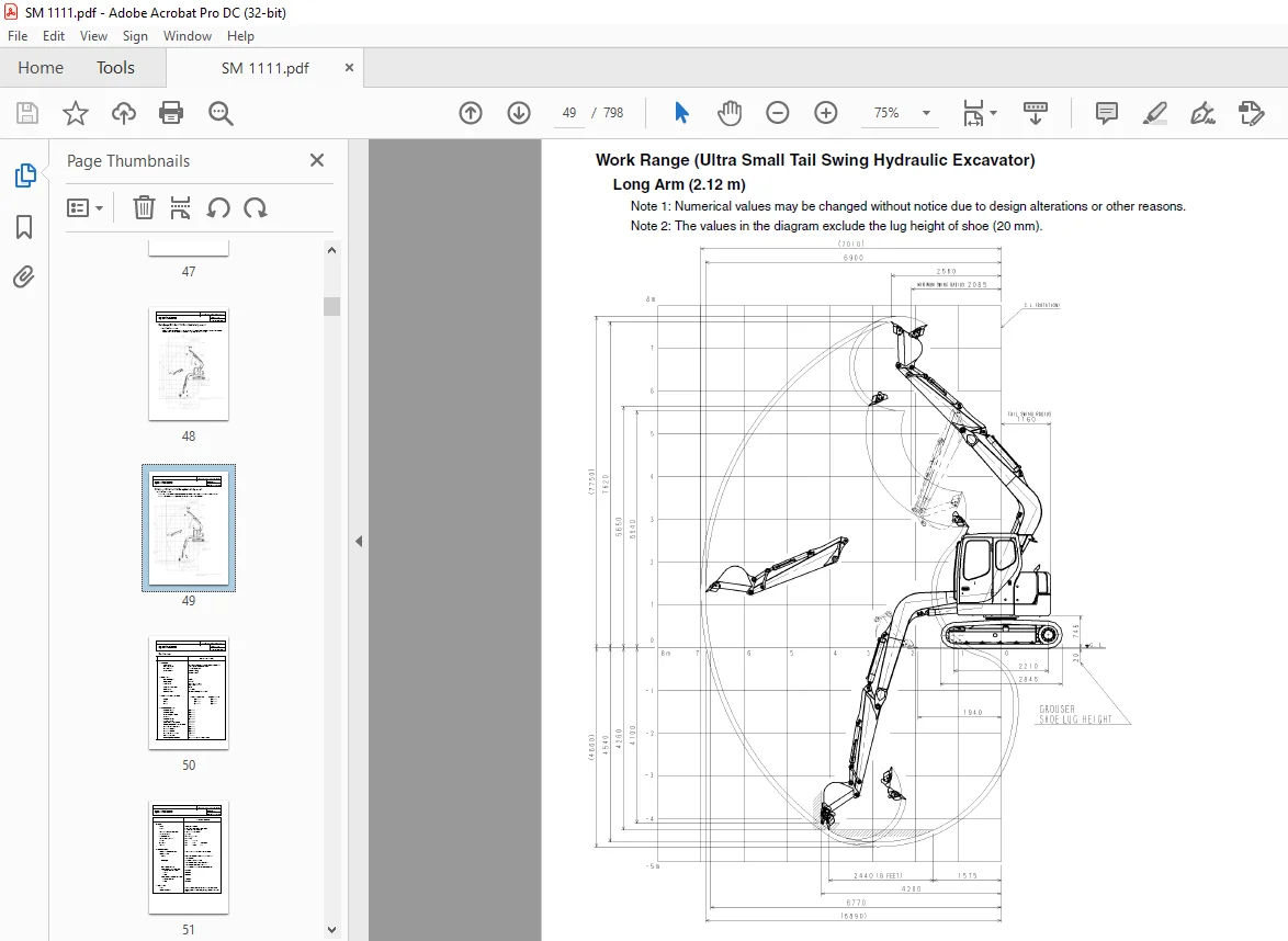
Work Range (Ultra Small Tail Swing Hydraulic Excavator) 075-1-01-02-10
Standard Arm (1 71 m) 1/2
Long Arm (2 12 m) 2/2
Specifications 075-1-01-00-10
1/5
Complete Machine Dimensions
(Ultra Small Tail Swing Hydraulic Excavator, with Blade) 075-1-01-01-11
Standard Arm (1 71 m) 1/2
Long Arm (2 12 m) 2/2
Work Range
(Ultra Small Tail Swing Hydraulic Excavator, with Blade) 075-1-01-02-11
Standard Arm (1 71 m) 1/2
Long Arm (2 12 m) 2/2
Specifications 075-1-01-00-11
1/5
Complete Machine Dimensions
(Ultra Small Swing Hydraulic Excavator) 075-1-01-01-12
Standard Arm (1 75 m) 1/2
Long Arm (2 10 m) 2/2
Work Range (Ultra Small Swing Hydraulic Excavator) 075-1-01-02-12
Standard Arm (1 75 m) 1/2
Long Arm (2 10 m) 2/2
Optional Components 075-1-01-03-06
List of Optional Components 1/1
Major Equipment Specifications
Equipment Configuration 075-2-01-00-02
Overall 1/3
Operator’s Cab 2/3
Lower Mechanism 075-2-01-01-29
Lower Assembly Diagrams (Overall) 1/4
Travel Unit (with Parking Brake) 3/4
Take-up Roller 3/4
Upper Roller 3/4
Lower Roller (External Roller) 3/4
Recoil Spring 4/4
Shoes 4/4
Upper Mechanism 075-2-01-02-29
Swing Unit 1/1
Engine and Related Areas 075-2-01-03-29
Engine 1/4
Performance Curve of Diesel Engine 2/4
Muffler 3/4
Air Cleaner (Single Element) 3/4
Radiator 3/4
Fuel Tank 4/4
Hydraulic System 075-2-01-04-29
Hydraulic Pump 1/8
Sump Tank 5/8
Rotating Joint 6/8
Solenoid Valve 8/8
Controls 075-2-01-05-30
Remote Control Valve (Left/Right, Travel Operations) 1/5
Control Valve 5/5
Backhoe Attachments 075-2-01-06-31
Cylinder 1/3
Attachments 3/3
Hydraulics Section
Hydraulic Pump: Operational Description 075-1-02-01-03
1 Configuration and Principle of Operation 1/4
2 Flow Control 3/4
Control Valve: Operation 075-1-02-02-03
1 Operation with All Spools in Neutral 1/15
1-1 Main passage 1/15
1-2 Signal passage 1/15
2 Independent Operation 3/15
2-1 Travel spool switch-over 3/15
2-2 Backup spool switch-over 3/15
2-3 Swing spool switch-over 4/15
2-4 Basket spool switch-over 4/15
2-5 Boom spool switch-over 5/15
2-6 Arm spool switch-over 7/15
2-7 Blade spool switch-over (Add-on) 9/15
2-8 Relief valve 9/15
2-9 Anti-drift valve (Boom section) 10/15
3 Combined Operations 13/15
3-1 Additional operation with travel 13/15
4 Relief Valve 14/15
4-1 Main relief valve 14/15
4-2 Overload relief valve 15/15
Swing Unit: Swing Motor 075-1-02-03-02
Functional and Operational Description 1/8
1 Swash Plate Motor 1/8
2 Parking Brake (for models equipped with parking brakes) 3/8
3 Principle of Relief Valve Operation 4/8
4 Makeup Valve 7/8
5 Reduction Gear (2-stage planetary gear) 8/8
Swing Unit: Anti-Reverse Valve 075-1-02-03-03
1 Overview 1/5
1-1 Features 1/5
2 Operational Description 2/5
Travel Unit: Travel Motor 075-1-02-04-04
1 External Dimensional Drawing 1/13
2 Basic Structure and Drawings 2/13
2-1 Basic structure of GM motor 2/13
2-2 Parts list 4/13
3 Operational Description 5/13
3-1 Reduction gears 5/13
3-2 Hydraulic drive section 7/13
Hydraulic Circuits Section
Port Locations 075-1-03-00-05
Hydraulic Pump 1/5
Control Valve 3/5
Pilot Hose Connection Diagrams 075-1-03-01-05
Pilot P&T Lines 1/8
Pilot Control Lines 5/8
Functional Description 075-1-03-02-05
List of Functions 1/3
Control valve Configuration Table 3/3
Travel Circuits 075-1-03-03-05
High-Speed Travel Circuit 1/6
Low-Speed Travel Circuit 3/6
Straight-Travel Circuit (Boom-Up and Travel-Forward) 5/6
Swing Circuits 075-1-03-04-05
Swing Parking Circuit 1/4
Swing Override Throttle Circuit 3/4
Arm Circuits 075-1-03-06-05
Arm-In/Arm-Out 2-speed Circuit 1/2
Boom Circuits 075-1-03-07-05
Boom-Up 2-speed Circuit 1/4
Boom-Down Load Holding Valve Circuit 3/4
Backup Circuits 075-1-03-09-03
Breaker/Crusher Circuit (2-speed Confluence Crusher Circuit) 1/9
Breaker/Crusher Circuit (Backup Line Holding Valve) 3/9
Breaker/Crusher Circuit (Breaker Circuit)
Ultra Small Tail Swing Hydraulic Excavator 4/9
Backup Reciprocating Circuit (Ultra Small Swing Hydraulic Excavator) 6/9
Secondary Backup Reciprocating Circuit
(Ultra Small Tail Swing Hydraulic Excavator) 8/9
Hydraulic Circuit Diagrams 075-1-07-00-05
Electric Circuits Section
Operational Description 075-1-04-01-03
Monitor Display 1/21
List of Functions 2/21
1 Engine Controls 3/21
1-1 Engine start control 3/21
1-2 Throttle control 5/21
1-3 One-touch idle 7/21
1-4 Crane mode 8/21
2 Monitor Output Control 10/21
2-1 2-speed travel 10/21
2-2 Swing brake 11/21
2-3 Travel alarm 12/21
2-4 Working light 13/21
2-5 Windshield wiper / windshield washer 14/21
2-6 Power cut delay 16/21
3 Monitor Display Control 17/21
3-1 Overheat warning 17/21
3-2 Engine oil pressure warning 18/21
3-3 Low fuel warning 19/21
3-4 Battery charge warning 20/21
3-5 Auto preheat 21/21
Electric Circuit Diagrams 075-1-07-01-03
Electric Circuit Diagrams 1 1/14
Electric Circuit Diagrams 2 2/14
Electric Circuit Diagrams 3 3/14
Electric Circuit Diagrams 4 4/14
Electric Circuit Diagrams 5 5/14
Electric Circuit Diagrams: Interference Prevention 1 6/14
Electric Circuit Diagrams: Interference Prevention 2 7/14
Electric Circuit Diagrams: Air Conditioner 1 8/14
Electric Circuit Diagrams: Air Conditioner 2 9/14
Electric Circuit Diagrams: Heater Circuit 10/14
Electric Circuit Diagrams: Crane Specification 1 11/14
Electric Circuit Diagrams: Crane Specification 2 12/14
Electric Circuit Diagrams (A3 version) 13/14
Wiring Diagrams 075-1-04-07-02
Electrical Components and Wiring for Upper Frame 1/3
Electrical Components and Wiring for Cab 2/3
Harness Diagrams 075-1-04-08-02
Upper Frame 1/2
Inside Cab 2/2
Assembly Drawings 075-1-04-09-01
Heater 1/5
Air Conditioner 2/5
Inside Cab 2/5
Frame 4/5
Maintenance Section
Measuring/Adjusting Pressure 075-1-05-00-05
1 Measuring Pressure 1/9
A Basic conditions 1/9
B Pressure settings 1/9
C Ports for measuring pressure 2/9
D Preparation for measuring pressure 3/9
E Measuring pressure 5/9
2 Pressure Adjustment 7/9
A Pressure adjustment 7/9
3 Bleeding Air 9/9
Compatibility 075-1-05-05-03
List of Common Features and Compatibility of Major Parts 1/4
Dimensions of Bucket and Peripheral 075-1-05-04-04
Bucket Dimensions 1/2
Arm Dimensions 2/2
Assembling with Non-Sumitomo Components 075-1-05-11-01 1/2
Replacement of Rubber Shoes and Iron Shoes 075-1-05-12-01 1/1
Interference Prevention Section
Functions 075-1-09-00-01
System Functions 1/5
Interference Prevention System 2/5
Temporary Release Function 4/5
Abnormal Process 5/5
Description of Circuits 075-1-09-01-01
Boom (Up) Interference Prevention Function 1/12
Offset (Left) Interference Prevention Function 3/12
Arm (In) Interference Prevention Function 5/12
Temporary Release Stop Function 7/12
Abnormal Process (Shut-off Function) 9/12
Abnormal Process (Backup Function) 11/12
Setup Procedures 075-1-09-02-01
Initial Setting Procedures 1/2
Verifying the Settings 075-1-09-03-01
Verifying the Proper Functioning of Cab Interference Prevention 1/5
Verifying the Emergency Release Function 5/5
Troubleshooting 075-1-09-04-01
Error Warnings 1/7
1 Troubleshooting the Angle Sensor 3/7
2 Troubleshooting the Proportional Valve 4/7
3 Troubleshooting of Over-approach 5/7
4 Measuring Interference Prevention Devices 6/7
Contact us: [email protected]
https://vimeo.com/891712795?share=copy
S.S