Trusted Business
Verified & Licensed
Virus Free Files
100% Safe Downloads
Secure Payment
SSL Protected
Instant Delivery
Available Immediately
Link-Belt Sumitomo 750X4 Excavator SERVICE MANUAL WLSM7007-00LX – PDF DOWNLOAD
$37.95
Link-Belt Sumitomo 750X4 Excavator SERVICE MANUAL WLSM7007-00LX – PDF DOWNLOAD
Instant PDF Download
Available immediately
Save to Your Device
Download & keep forever
Antivirus Scanned
100% virus-free
Trusted Worldwide
175,000+ customers
Description
Link-Belt Sumitomo 750X4 Excavator SERVICE MANUAL WLSM7007-00LX – PDF DOWNLOAD
FILE DETAILS:
Link-Belt Sumitomo 750X4 Excavator SERVICE MANUAL WLSM7007-00LX – PDF DOWNLOAD
Language : English
Pages :2004
Downloadable : Yes
File Type : PDF
IMAGES PREVIEW OF THE MANUAL:
DESCRIPTION:
Link-Belt Sumitomo 750X4 Excavator SERVICE MANUAL WLSM7007-00LX – PDF DOWNLOAD
General Information
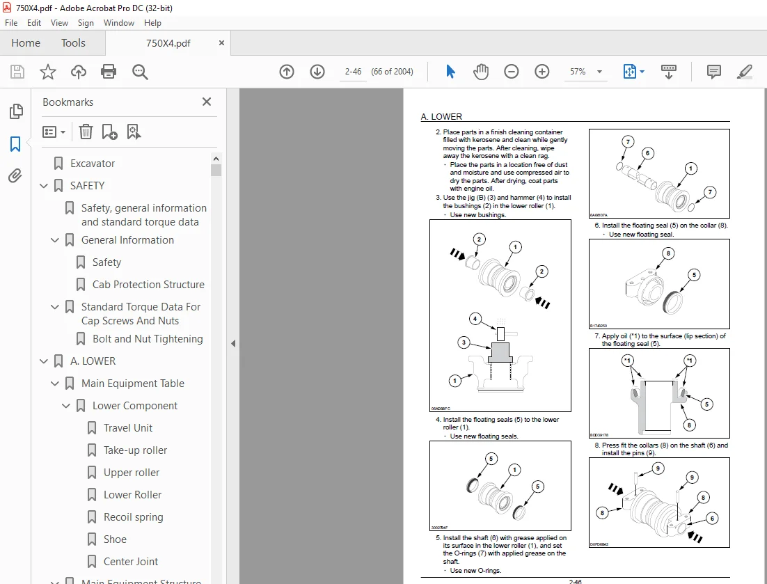
Cleaning Clean the metal parts with cleaning solution that meets the standard and steam cleaning. (except for bearings) After cleaning, dry well, and inject oil in all parts. Also inject oil into the bearings after drying. Inspection When disassembling parts, check all the parts.
- If there are any worn or damaged parts, replace them. Inspect carefully to prevent initial breakdowns. Bearing Replace any loose bearings. Air dry bearings before installing them. Needle bearing When inserting needle bearings, be very careful not to damage them. Apply grease to the section where the needle bearing will be inserted. Gear Check that there is no wear and no damage.
- Oil seal, O-ring, gasket Always install new oil seals, O-rings, and gaskets. Apply grease to sections where oil seals and O-rings will be inserted. Shaft Check that there is no wear and no damage. Check the bearings and check for damaged oil seals on the shaft.
- Service parts Install LBX Link-Belt genuine service parts. When placing an order, check the parts catalog. It contains the LBX Link-Belt genuine part numbers.
- Any breakdowns arising from the installation of non-genuine parts are not covered by the warranty. Lubricants (fuel, hydraulic oil) Use the oil from the specified company or specified in the operator’s manual or service manual. Any breakdowns arising from any fuel or hydraulic oil other than those specified are not covered by the warranty
TABLE OF CONTENTS:
Link-Belt Sumitomo 750X4 Excavator SERVICE MANUAL WLSM7007-00LX – PDF DOWNLOAD
Excavator 1
SAFETY 9
Safety, general information and standard torque data 12
General Information 13
Safety 13
Cab Protection Structure 15
Standard Torque Data For Cap Screws And Nuts 17
Bolt and Nut Tightening 17
A LOWER 19
Main Equipment Table 23
Lower Component 23
Travel Unit 23
Take-up roller 23
Upper roller 23
Lower Roller 23
Recoil spring 23
Shoe 23
Center Joint 24
Main Equipment Structure and Operation Explanation 25
Travel Motor 25
Operation principles 25
Hydraulic motor 25
Parking brake 26
II-speed switchover 28
Relief valve 33
Double counter balance valve 34
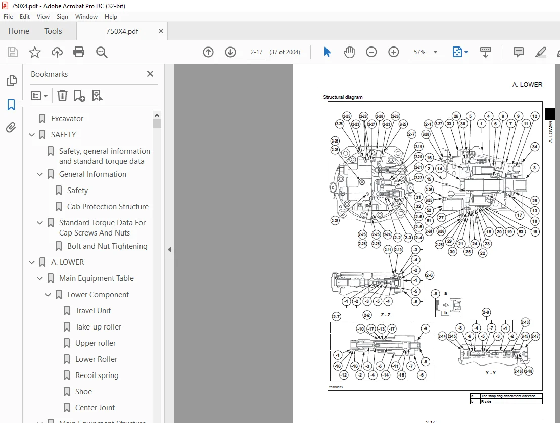
Structural diagram 37
Port Diagram 39
Travel Motor 39
Center Joint 40
Basic Functions 41
Travel Speed Selection 41
Travel Alarm 41
Removal and Installation of Track 43
Removal and Installation of Shoe Assembly 44
Removal of Shoe Assembly 44
Installation of Shoe Assembly 45
Removal and Installation of Shoe Plate 48
Removal of Shoe Plate 48
Installation of Shoe Plate 48
Removal and Installation of Roller 49
Removal and Installation of Upper Roller 50
Removal of Upper Roller 50
Installation of Upper Roller 51
Assembly and Disassembly of Upper Roller 53
Configuration diagram 54
Dimension diagram 55
Jig dimension diagram 55
Disassembly procedure 56
Assembly procedure 57
Removal and Installation of Lower Roller 59
Removal of Lower Roller 59
Installation of Lower Roller 60
Assembly and Disassembly of Lower Roller 62
Configuration diagram 63
Dimension diagram 64
Jig Dimension Diagram 64
Disassembly procedure 65
Assembly procedure 65
Removal and Installation of Retractable Lower Frame 68
Removal of Retract Lower 68
Mounting of Retract Lower 69
Removal and Installation of Drive Sprocket 70
Removal of Drive Sprocket 70
Installation of Drive Sprocket 71
Removal and Installation of Take-up Roller 72
Remove take-up roller 72
Installation of Take-up Roller 72
Assembly and Disassembly of Take-up Roller 74
Configuration diagram 75
Dimension diagram 76
Jig dimension diagram 76
Disassembly procedure 76
Assembly procedure 78
Removal and Installation of Grease Cylinder 81
Removal of Grease Cylinder 81
Installation of Grease Cylinder 81
Assembly and Disassembly of Grease Cylinder 82
Dimension Diagram 82
Removal and Installation of Center Joint 83
Removal of Center Joint 83
Installation of Center Joint 85
Disassembly and Assembly of Center Joint 86
Internal Structural Diagram 86
Removal and Installation of Travel Motor 88
Removal of Travel Motor 88
Installation of Travel Motor 90
Assembly and Disassembly of Travel Motor 93
Safety cautions 93
Tools for assembly and disassembly 98
Standard tools 98
Secondary materials 99
Special tool (jig) 100
Measurement devices 103
Disassembly procedure of motor 103
Precautions before motor disassembly 103
Tightening torque 104
Disassembly Procedure 104
Disassembly Procedure for Reduction Gear 110
Maintenance standards 113
Motor parts maintenance standards 113
Reduction gear parts maintenance standards 117
Assembly Procedure of Motor 117
Precautions before motor assembly 117
Assembly of Reduction Gear 117
Assembly of motor section 120
Quality check after assembly 129
Motor installation 129
Motor inspection 129
Operation check 130
Troubleshooting 132
Structural Diagram 139
Travel motor breakdown diagram 139
Travel Motor 142
Tightening torque 144
Travel motor part table 144
Reduction gear 146
Maintenance Standards 148
Drive sprocket 148
Take-up roller 149
Upper roller 150
Lower Roller 151
Track Shoe (Grouser Shoe) 152
Inspection Gauge 153
For Drive Sprocket 153
For Take-up Roller 153
For Upper Roller 154
For Lower Roller 154
Pressure Measurement and Adjustment Procedures 155
Main Pressure Measurement 155
B Travel Pressure Measurement 155
Drain Volume Measurement Procedures 157
Preparations 157
Travel Motor Drain Volume Measurement 157
Air Bleed Procedure 159
Travel Motor 159
B C SWING UNIT, COUNTERWEIGHT 161
Main Equipment Table 164
Upper Component 164
Swing Unit 164
Counterweight Removal System (Option) 165
Solenoid Valves (Counterweight Raise/Lower and Arm Top/Bottom) 165
Cylinder (Counterweight raise/arm top) 165
stop valve 165
Main Equipment Structure and Operation Explanation 166
Swing Motor 166
Operation principles 166
Hydraulic motor section 166
Anti-cavitation check valve section 166
Relief valve 166
Reverse prevention valve 169
Brake section 170
Internal structure diagram 171
Structure of Counterweight Removal System 174
Equipment Layout 174
Hydraulic circuit diagram 175
Electrical Circuit Diagram 176
Cylinder Structural Diagram 178
Port Diagram 182
Swing motor 182
Basic Functions 183
Swing Brake 183
Swing Lock 183
Swing Speed Limit 184
Swing Relief Cut 186
Counterweight Removal/Installation Mode 187
Removal and Installation of Swing Unit 189
Removal of Swing Unit 189
Installation of Swing Unit 191
Assembly and Disassembly of Swing Unit 192
Disassembly 192
Assembly 193
Assembly and Disassembly of Swing Motor 195
Causes of trouble and solutions 195
Maintenance procedures 197
Assembly and disassembly 198
Bolt tightening torque 198
Tools for assembly and disassembly 199
Brake piston removal jig 200
Disassembly procedure 200
Assembly procedure 202
Internal Structure Diagram 207
Removal and Installation of Counterweight 211
Removal of Counterweight 211
Installation of Counterweight 212
Removal and Installation of Counterweight Removal System 213
Component Layout Diagrams of Counterweight Removal System 213
Removal and Installation of Counterweight Removal System Cylinder 218
Removal of Counterweight Removal System Cylinder 218
Installation of Counterweight Removal System Cylinder 223
Removal and Installation of Counterweight Removal System Solenoid Valve 227
Removal of Counterweight Removal System Solenoid Valve 227
Installation of Counterweight Removal System Solenoid Valve 228
Pressure Measurement and Adjustment Procedures 230
Main Pressure Measurement 230
C Swing Pressure Measurement 230
Drain Volume Measurement Procedures 232
Preparations 232
Swing Motor Drain Volume Measurement 232
Air Bleed Procedure 233
Swing Motor 233
Check 233
H ENGINE 235
Main Equipment Table 243
Engine-related 243
Engine 243
Air Cleaner (double element) 243
Radiator 243
SCR 243
Basic Functions 245
Fuel Gauge 245
Coolant Temperature Gauge 246
SCR Gauge 248
Fuel Economy Gauge 251
Neutral Start 252
Power-cut Delay 253
Preheat 254
Throttle 255
Throttle Volume Position Detection 256
Idling Start 262
Auto Idle 262
One-touch Idle 263
Auto Warm-Up 264
Idle Shutdown 269
Idle Up 270
Work Mode Control 271
Engine Emergency Stop 272
SCR CLEANING 272
Inducement 277
Feed Pump Automatic Stop 282
Coolant Level Decrease 283
Air Filter Clogging 284
Fuel Filter Clogging 285
Battery Charge Abnormality 287
Horsepower Reduction Control (in Uplands) 288
Horsepower Reduction Control (at Engine Failure) 288
Main Data 291
Function, Structure, Operation 294
Function, Structure, and Operation of Emission Control 350
SCR Control System Inspection 379
Operation Explanation of SCR 380
Diagnosis for Each Symptom 382
Intermittent conditions of urea selective catalytic reduction system 382
Urea fluid consumption too high 385
Ammonia smell noticeable 385
White crystalline powder visible 386
Symptom 387
Engine start failure 387
Engine stalling 388
Engine hunching, rough idling 390
Excess Amount of White Smoke in Exhaust Gas 391
Excess Amount of Black Smoke in Exhaust Gas 391
Abnormal Noise 392
Large fuel consumption 392
Large oil consumption 394
Insufficient engine output 394
Functional Inspection 397
Engine compression pressure inspection 397
Inspection of the fuel system 398
Inspection of the air intake system 398
Inspection of the exhaust system 399
Inspection of EGR Control System 399
Inspection of the starting system 399
Inspection of glow control system 400
OBD System Check 401
Inspection of monitor warning lamp lighting circuit system 402
Inspection of monitor warning lamp flashing circuit system 402
Inspection of starting circuit system 403
Removal and Installation of Engine Assembly 405
Removal of Engine Assembly 405
Installation of Engine Assembly 408
Removal and Installation of Fuel Cooler, Engine Intercooler, Radiator, and Oil Cooler 409
Removal and Installation of Fuel Cooler 409
Removal of Fuel Cooler 409
Installation of Fuel Cooler 409
Removal and Installation of Engine Intercooler 409
Removal of Intercooler 410
Installation of Inter Cooler 410
Inspection of Intercooler 410
Removal and Installation of Radiator 411
Removal of Radiator 411
Installation of Radiator 413
Inspection of Radiator 413
Removal and Installation of Oil Cooler 414
Installation of oil cooler 415
Installation of oil cooler 415
Removal and Installation of Hydraulically-Operated Fan 415
Removal of Hydraulically-Operated Fan 415
Installation of Hydraulically-Operated Fan 416
Removal and Installation of Turbo Charger 417
Removal of Turbocharger assembly 417
Installation of Turbocharger assembly 419
Inspection of Turbocharger assembly 422
Removal and Installation of EGR Valve 424
Removal of EGR Valve 424
Installation of EGR Valve 427
Removal and Installation of EGR Cooler 435
Removal of EGR cooler 435
Installation of EGR cooler 438
Inspection of EGR cooler 444
Removal and Installation of Engine Hood 446
Removal of Engine Hood 446
Installation of Engine Hood 448
Removal and Installation of SCR 449
Removal of SCR 449
Installation of SCR 450
Removal and installation of Silicon Controlled Rectifier Catalyst 451
Removal of Silicon Controlled Rectifier Catalyst 451
Installation of Silicon Controlled Rectifier Catalyst 453
Disassembly of Silicon Controlled Rectifier Catalyst 456
Assembly of Silicon Controlled Rectifier Catalyst 456
Inspection of Silicon Controlled Rectifier Catalyst 456
Removal and Installation of Cylinder Head Cover 457
Removal of Cylinder head cover 457
Installation of Cylinder head cover 457
Removal and Installation of Cylinder Head 458
Removal of Cylinder head assembly 458
Disassembly of Cylinder head assembly 468
Reassembly of Cylinder head assembly 470
Installation of Cylinder head assembly 477
Inspection of Cylinder head assembly 497
Removal and Installation of Cylinder Block 503
Removal of Cylinder Block 503
Disassembly of Cylinder Block 521
Reassembly of Cylinder Block 522
Installation of Cylinder Block 524
Inspection of Cylinder Block 563
Lubrication System 565
Removal and Installation of Oil Pan 565
Removal of Oil Pan 565
Installation of Oil Pan 565
Removal and Installation of Oil Level Switch 567
Removal of Oil Level Switch 567
Installation of Oil Level Switch 567
Removal and Installation of Oil Pump Assembly 567
Removal of Oil Pump Assembly 567
Installation of Oil Pump Assembly 569
Inspection of Oil Pump Assembly 574
Removal and Installation of Oil Cooler Assembly 574
Removal of Oil Cooler Assembly 574
Disassembly of Oil Cooler Assembly 577
Reassembly of Oil Cooler Assembly 578
Installation of Oil Cooler Assembly 579
Inspection of Oil Cooler Assembly 585
Inspection of Engine Oil 585
Removal and installation of Piston oil jet 585
Removal of Piston oil jet 585
Installation of Piston oil jet 586
Removal and installation of Oil filter element 589
Removal of Oil Filter Element 589
Installation of Oil Filter Element 589
Removal and Installation of Oil Separator Element 589
Removal of Oil Separator Element 589
Installation of Oil Separator Element 589
Cooling System 590
Removal and Installation of Water Pump Assembly 590
Removal of Water Pump Assembly 590
Installation of Water Pump Assembly 591
Disassembly of Water Pump Assembly 595
Reassembly of Water Pump Assembly 596
Inspection of Water Pump Assembly 598
Removal and Installation of Thermostat 599
Removal of Thermostat 599
Installation of Thermostat 600
Inspection of Thermostat 603
Inspection of Coolant 604
Removal and installation of Generator drive belt 608
Removal of Drive Belt 608
Installation of Drive Belt 609
Inspection of Drive Belt 609
Removal and Installation of Overheat Switch 609
Removal of Overheat Switch 609
Installation of Overheat Switch 610
Induction System 611
Inspection of Air cleaner element 611
Exhaust System 612
Removal and installation of Oxidation Catalyst Assembly 612
Removal of Oxidation Catalyst Assembly 612
Installation of Oxidation Catalyst Assembly 613
Aux Emission Control Devices System 615
Removal and installation of Dosing Module 615
Removal of Dosing Module 615
Disassembly of Dosing Module 615
Assembly of Dosing Module 616
Installation of Dosing Module 616
Removal and installation of DEF Supply Module 618
Removal of DEF supply module 618
Disassembly of DEF Supply Module 619
Assembly of DEF Supply Module 619
Installation of DEF Supply Module 620
Removal and installation of Coolant Control Valve 622
Removal of Coolant Control Valve 622
Installation of Coolant Control Valve 623
Removal and Installation of DCU 625
Removal of DCU 625
Installation of DCU 625
Removal and installation of DEF Supply Module Filter 625
Removal of DEF Supply Module Filter 625
Installation of DEF Supply Module Filter 626
Removal and Installation of Fuel Tank 627
Removal of Fuel Tank 627
Installation of Fuel Tank 629
Removal and Installation of Urea Pump 630
Removal of Urea Pump 630
Installation of Urea Pump 631
Removal and Installation of Urea Solution Tank 632
Removal of Urea Solution Tank 632
Installation of Urea Solution Tank 633
Removal and Installation of Fuel Supply Pump 634
Removal of Fuel Supply Pump 634
Installation of Fuel Supply Pump 635
Inspection of Fuel Supply Pump 640
Removal and Installation of Common Rail Assembly 641
Removal of Common Rail Assembly 641
Installation of Common Rail Assembly 645
Removal and Installation of Injector 657
Removal of Injector 657
Installation of the Injector 663
Removal and installation of Idle Gear 676
Removal of Idle Gear 676
Installation of Idle Gear 688
Inspection of Idle Gears 712
Removal and installation of Crankshaft 713
Removal of Crankshaft 713
Installation of Crankshaft 731
Disassembly of Crankshaft 770
Reassembly of Crankshaft 771
Inspection of Crankshaft 772
Removal and installation of Piston 775
Removal of Piston 775
Installation of Piston 786
Disassembly of Piston 811
Reassembly of Piston 812
Inspection of Piston 814
Removal and installation of Camshaft 819
Removal of Camshaft 819
Installation of Camshaft 821
Disassembly of Camshaft 826
Reassembly of Camshaft 826
Inspection of Camshaft 826
Removal and installation of Flywheel 829
Removal of Flywheel 829
Installation of Flywheel 829
Disassembly of Flywheel 830
Reassembly of Flywheel 830
Inspection of Flywheel 830
Removal and Installation of Flywheel housing 831
Removal of Flywheel housing 831
Installation of Flywheel housing 832
Removal and Installation of Timing Gear Case 837
Removal of Timing Gear Case 837
Installation of Timing Gear Case 850
Removal and installation of Rocker Arm Shaft 880
Removal of Rocker Arm Shaft 880
Installation of Rocker Arm Shaft 881
Disassembly of Rocker Arm Shaft 885
Reassembly of Rocker Arm Shaft 885
Inspection of Rocker Arm Shaft 886
Removal and installation of Intake Throttle Valve 888
Removal of Intake Throttle Valve 888
Installation of Intake Throttle Valve 888
Removal and Installation of Starter Motor 889
Removal of Starter Motor 889
Installation of Starter Motor 889
Disassembly of Starter Motor 889
Reassembly of Starter Motor 892
Inspection of Starter Motor 894
Removal and Installation of Alternator 898
Removal of Alternator 898
Installation of Alternator 898
Disassembly of Alternator 898
Reassembly of Alternator 901
Inspection of Alternator 902
Removal and Installation of Glow Plug 906
Removal of Glow Plug 906
Installation of Glow Plug 908
Glow plug Inspection 915
Removal and installation of Fuel Filter 916
Removal of Fuel Filter 916
Installation of Fuel Filter 916
Removal and installation of Relief Valve 919
Removal of Relief Valve 919
Installation of Relief Valve 919
Removal and installation of Fuel Filter Element 920
Removal of Fuel Filter Element 920
Installation of Fuel Filter Element 920
Removal and installation of Fuel temperature sensor 922
Removal of Fuel Temperature Sensor 922
Installation of Fuel Temperature Sensor 922
Inspection of Fuel Temperature Sensor 923
Removal and installation of Pressure limiter 924
Removal of Pressure Limiter 924
Installation of Pressure Limiter 924
Removal and installation of Fuel pressure sensor 927
Removal of Fuel Pressure Sensor 927
Installation of Fuel Pressure Sensor 927
Inspection of Fuel pressure sensor 927
Removal and Installation of Fuel filter pressure 928
Removal of Fuel filter pressure sensor 928
Installation of Fuel filter pressure sensor 928
Removal and Installation of Engine coolant temperature sensor 929
Removal of Coolant Temperature Sensor 929
Installation of Coolant Temperature Sensor 929
Engine coolant temperature sensor Inspection 931
Removal and Installation of CKP sensor 933
Removal of Crankshaft Position (CKP) Sensor 933
Installation of Crankshaft Position (CKP) Sensor 933
Inspection of Crankshaft Position (CKP) Sensor 933
Removal and Installation of CMP sensor 934
Removal of Camshaft Position (CMP) Sensor 934
Installation of Camshaft Position (CMP) Sensor 934
Inspection of Camshaft Position (CMP) Sensor 934
Removal and Installation of Oil Pressure Sensor 935
Removal of Oil Pressure Sensor 935
Installation of Oil Pressure Sensor 935
Removal and installation of Pressure Sensor/Boost Temperature Sensor 936
Removal of Pressure Sensor/Boost Temperature Sensor 936
Installation of Pressure Sensor/Boost Temperature Sensor 936
Inspection of Pressure sensor/boost temperature sensor 936
Removal and Installation of IMT sensor 937
Removal of IMT sensor 937
Installation of IMT sensor 937
Removal and installation of MAF and IAT sensor 938
Removal of MAF and IAT sensor 938
Installation of MAF and IAT sensor 938
Inspection of MAF and IAT sensor 938
Removal and installation of Charge Air Cooler Temperature Sensor 1 940
Removal of Charge Air Cooler Temperature Sensor 1 940
Installation of Charge Air Cooler Temperature Sensor 1 940
Inspection of Charge air cooler temperature sensor 1 940
Sampling Procedure 941
Sampling of Engine Oil 941
Removal and Installation of Exhaust gas temperature sensor 942
Removal of Exhaust gas temperature sensor 942
Installation of Exhaust gas temperature sensor 942
Inspection of Exhaust gas temperature sensor 943
Removal and installation of EGR Gas Temperature Sensor 1 944
Removal of EGR Gas Temperature Sensor 1 944
Installation of EGR Gas Temperature Sensor 1 944
Inspection of EGR Gas Temperature Sensor 1 944
Removal and installation of EGR Gas Temperature Sensor 2 946
Removal of EGR Gas Temperature Sensor 2 946
Installation of EGR Gas Temperature Sensor 2 946
Inspection of EGR Gas Temperature Sensor 2 946
Removal and installation of EGR Gas Temperature Sensor 3 948
Removal of EGR Gas Temperature Sensor 3 948
Installation of EGR Gas Temperature Sensor 3 948
Inspection of EGR Gas Temperature Sensor 3 948
Removal and installation of EGR Gas Temperature Sensor 4 950
Removal of EGR Gas Temperature Sensor 4 950
Installation of EGR Gas Temperature Sensor 4 950
Inspection of EGR Gas Temperature Sensor 4 950
Removal and installation of NOx Sensor 952
Removal of NOx Sensor 952
Installation of NOx Sensor 952
Removal and Installation of Exhaust gas temperature sensor 3 955
Removal of Exhaust gas temperature sensor 3 955
Installation of Exhaust gas temperature sensor 3 955
Removal and installation of DEF Sensor 957
Removal of DEF Sensor 957
Installation of DEF Sensor 957
Engine-related Diagnostic Trouble Code List 958
Engine-side Trouble 965
ECM Trouble 965
DTC P0016 Crankshaft Position – Camshaft Position Correlation Error 965
DTC P0045
Turbocharger Boost Control VNT Error 965
DTC P0087
Fuel Rail/System Pressure – Too Low 967
DTC P0089
Fuel Pressure Regulator Performance 969
DTC P0091
Fuel Pressure Regulator Control Circuit Low 971
DTC P0092
Fuel Pressure Regulator Control Circuit High 971
DTC P0097 Intake Air Temperature (IAT) Sensor 2 Circuit Low Voltage 972
DTC P0098 Intake Air Temperature (IAT) Sensor 2 Circuit High Voltage 972
DTC P0102 Mass Air Flow Sensor Circuit Low Input 974
DTC P0103 Mass Air Flow Sensor Circuit High Input 974
DTC P0112 Intake Air Temperature Sensor Circuit Low 975
DTC P0113 Intake Air Temperature Sensor Circuit High 975
DTC P0117 Engine Coolant Temperature Sensor Circuit Low 976
DTC P0118 Engine Coolant Temperature Sensor Circuit High 977
DTC P0122 Throttle Position Sensor Circuit Low 978
DTC P0123 Throttle Position Sensor Circuit High 979
DTC P0182
Fuel Temperature Sensor Circuit Low 980
DTC P0183
Fuel Temperature Sensor Circuit High 980
DTC P0192
Fuel Rail Pressure Sensor Circuit Low 981
DTC P0193
Fuel Rail Pressure Sensor Circuit High 982
DTC P0201 Injector Circuit Open – Cylinder 1 983
DTC P0202 Injector Circuit Open – Cylinder 2 983
DTC P0203 Injector Circuit Open – Cylinder 3 984
DTC P0204 Injector Circuit Open – Cylinder 4 985
DTC P0205
Injector Circuit Open – Cylinder 5 986
DTC P0206
Injector Circuit Open – Cylinder 6 987
DTC P0217 Engine Coolant Over Temperature Condition 987
DTC P0219 Engine Overspeed Condition 988
DTC P0234
Turbocharger Overboost Condition 989
DTC P0237 Turbo Charger Boost Sensor Circuit Low 990
DTC P0238 Turbo Charger Boost Sensor Circuit High 990
DTC P0335 Crankshaft Position Sensor Circuit 991
DTC P0336 Crankshaft Position Sensor Circuit Range/Performance 992
DTC P0340
Camshaft Position Sensor Circuit 993
DTC P0380 Glow Relay Circuit Error 994
DTC P0401 EGR Flow Insufficient Detected 995
DTC P0404
EGR Control Circuit Range/Performance 996
DTC P0409 EGR Sensor Circuit 996
DTC P040C
EGR Cooler Outlet 2 Temp Sensor Circuit Low 998
DTC P040D
EGR Cooler Outlet 2 Temp Sensor Circuit High 998
DTC P041C EGR Cooler Outlet 1 Temp Sensor Circuit Low 999
Diagnostic trouble code_P041D: EGR cooler outlet 1 gas temperature sensor abnormality (High voltage abnormality)1000
DTC P0427 Catalyst Temperature Sensor Circuit Low Sensor 11001
DTC P0428 Catalyst Temperature Sensor Circuit High Sensor 11001
DTC P042C Catalyst Temperature Sensor Circuit Low Sensor 21003
DTC P042D Catalyst Temperature Sensor Circuit High Sensor 21003
DTC P045B
EGR 2 Control Circuit Range/Performance1004
DTC P0522 Engine Oil Pressure Sensor Circuit Low Input1005
DTC P0523 Engine Oil Pressure Sensor Circuit High Input1005
Diagnostic trouble code_P0545: EGR cooler inlet 1 gas temperature sensor abnormality (Low voltage abnormality)1006
Diagnostic trouble code_P0546: EGR cooler inlet 1 gas temperature sensor abnormality (High voltage abnormality)1007
DTC P0548 EGR Cooler Inlet 2 Temp Sensor Circuit Low1008
DTC P0549 EGR Cooler Inlet 2Temp Sensor Circuit High1008
DTC P0560
12 Volt Circuit Error1009
DTC P0563 System Voltage High1010
DTC P0601 Internal Control Module Memory Check Sum Error1010
DTC P0602 Internal Control Module QR Code Error1011
DTC P0604 Internal Control Module RAM Error1011
DTC P0606 Internal Control Module CPU Error1012
DTC P060A Internal Control Module CPU IC Error1012
DTC P060C Internal Control Module A/D Processing Performance1012
DTC P0615 Starter Relay Circuit Error1012
DTC P0638 Throttle Actuator Control Range/Performance1013
DTC P0685 ECM Power Relay Control Circuit Open1014
DTC P0687 ECM Power Relay Control Circuit High1015
DTC P06A6 Sensor Reference Voltage 1 Circuit1015
DTC P06A7
Sensor Reference Voltage 2 Circuit1016
DTC P06A8 Sensor Reference Voltage 3 Circuit1017
DTC P06A9 Sensor Reference Voltage 4 Circuit1018
DTC P06AF Torque Management System – Forced Engine Shutdown1019
DTC P06D5 Sensor Reference Voltage 5 Circuit1019
DTC P1062
Fuel Pressure Regulator 1 Solenoid Control Circuit1019
DTC P1063
Fuel Pressure Regulator 2 Solenoid Control Circuit1020
DTC P1076 Charge Air Cooler (CAC) Temperature Sensor 1 Circuit Low Voltage1020
DTC P1077 Charge Air Cooler (CAC) Temperature Sensor 1 Circuit High Voltage1021
DTC P1093
Fuel Rail Pressure Too Low1022
DTC P1097 Compressor Outlet Temperature Sensor Circuit High1023
DTC P1098 Compressor Outlet Temperature Sensor Circuit High1023
DTC P1236 Charge Air Cooler Performance Failure1025
DTC P1261 Injector Positive Voltage Control Circuit Group 11025
DTC P1262 Injector Positive Voltage Control Circuit Group 21026
DTC P1404
EGR Position Fault1026
DTC P140B EGR 2 Position Sensor Performance1026
DTC P140C EGR 2 Closed Position Performance1028
DTC P1606 SW-IC Internal failure1028
DTC P160B AD-IC Failure Error1029
DTC P160C AD-IC2 Failure Error1029
Diagnostic trouble code_P1621: EEPROM abnormality1029
DTC P1622
Control Module EEPROM Hardware Error1030
DTC P1669 DPD Lamp Control Circuit1031
DTC P204F SCR System Error (No Inducement)1032
DTC P207F Urea Fluid Concentration Too Low1032
DTC P20C9 SCR System Error1032
DTC P20DF
Exhaust After-treatment Fuel Pressure Sensor Circuit Low1033
DTC P20E0
Exhaust After-treatment Fuel Pressure Sensor Circuit High1033
DTC P2146
Fuel Injector Group 1 Supply Voltage Circuit1034
DTC P2149
Fuel Injector Group 2 Supply Voltage Circuit1035
DTC P2228 Barometric Pressure Sensor Circuit Low1036
DTC P2229 Barometric Pressure Sensor Circuit High1037
DTC P2295
Fuel Pressure Regulator 2 Control Circuit Low1037
DTC P2296
Fuel Pressure Regulator 2 Control Circuit High1038
DTC P2457 (Flash Code 95, 395)
Exhaust Gas Recirculation (EGR) Cooling System Performance1038
DTC P2458 Purge time Out Error1039
DTC P2BA7 Urea Fluid Quantity Too Low1040
DTC P2BAA SCR System Error (Inducement, No Purge)1040
DTC P3093
Fuel Rail Pressure Too Low1040
DTC U0001
CAN Bus Error (ISO-CAN)1042
DTC U0073 Control Module Communication Bus Off1043
DTC U0101 Lost Communication With CAN1044
DTC U010E Lost Communications With Dosing Control Module1045
DTC U0110
Lost Communication With VNT System1046
DTC U2106 Lost CAN Communications With Wheel Loader Transmission Control System1046
DTC U0411 Lost CAN Communications With VNT Control Module1047
DCU Trouble1047
DTC P0607 Control Module Performance1047
DTC P060B Internal Control Module A/D Processing Performance1048
DTC P062F Control Module EEPROM Error1048
DTC P0641 Sensor Reference Voltage 1 Circuit1049
DTC P0658 Actuator Supply Voltage Circuit1050
DTC P0659 Actuator Supply Voltage Circuit1051
DTC P1462 Urea Fluid Quality Sensor Timeout Error1052
DTC P1464 Main Relay Performance1053
DTC P1468 DCU Overtemperature1054
DTC P1491 Urea Fluid Overpressure1054
DTC P1493 DCU Driver Overtemperature1056
DTC P149C Urea Fluid Pressure Reduction Malfunction1056
DTC P149D Urea Solution Tank High Temperature Abnormality1058
DTC P2000 Monitoring the NOx Efficiency1059
DTC P203B Urea Fluid Tank Level Sensor Stuck1060
DTC P203C Urea Fluid Tank Level Sensor Low Voltage1062
DTC P203D Urea Fluid Tank Level Sensor High Voltage1062
DTC P2048 Urea Fluid Injector Circuit Low Voltage1063
DTC P2049 Urea Fluid Injector Circuit High Voltage1064
DTC P204B Urea Fluid Pressure Sensor Performance1065
DTC P204C Urea Fluid Pressure Sensor Circuit Low Voltage1066
DTC P204D Urea Fluid Pressure Sensor Circuit High Voltage1066
DTC P205B Urea Fluid Tank Temperature Sensor Performance1068
DTC P205C Urea Fluid Tank Temperature Sensor Low Voltage1068
DTC P205D Urea Fluid Tank Temperature Sensor High Voltage1069
DTC P206A Urea quality sensor system1070
DTC P206B Urea Sensor Over Temperature Condition1070
DTC P206C Open circuit/short circuit in the urea quality sensor circuit1071
DTC P206D Open circuit/short circuit in the urea quality sensor circuit 1072
DTC P207F Urea Fluid Concentration Too Low1072
DTC P208A Urea Fluid Pump Control Circuit1073
DTC P208B Usea Fluid Pump Performance1074
DTC P208C Urea Fluid Pump Control Circuit Low Voltage1075
DTC P208D Urea Fluid Pump Control Circuit High Voltage1076
DTC P208E Urea Fluid Injector Stuck1076
DTC P20A0 Urea Fluid Reverting Valve Circuit Open1078
DTC P20A2 Urea Fluid Reverting Valve Circuit Low Voltage1078
DTC P20A3 Urea Fluid Reverting Valve Circuit High Voltage1079
DTC P20AC Urea Fluid Pump Temperature Sensor Performance1080
DTC P20AD Urea Fluid Pump Module Temperature Sensor Performance1081
DTC P20B1 Urea Fluid Tank Heater Coolant Control Valve Circuit Open1082
DTC P20B3 Urea Fluid Tank Heater Coolant Control Valve Circuit Low Voltage1083
DTC P20B4 Urea Fluid Tank Heater Coolant Control Valve Circuit High Voltage1084
DTC P20E8 Urea Fluid Pressure Underpressure1085
DTC P20E9 Urea Fluid Overpressure1086
DTC P20EA Urea Fluid Pressure Reduction Malfunction1088
DTC P20FE Urea Fluid Pressure Build-Up Error1088
DTC P2201 Upstream Nox Sensor Performance1090
DTC P2206 Reading the error(open) information detected by Ft NOx sensor1090
DTC P2207 Reading the error(short) information detected by Ft NOx sensor1091
DTC P2210 Reading the error(open) information detected by Rr NOx sensor1091
DTC P2211 Reading the error(short) information detected by Rr NOx sensor1092
DTC P242B Exhaust Gas Temperature (EGT) Sensor 3 Performance1092
DTC P242C Exhaust Gas Temperature (EGT) Sensor 3 Circuit Low Voltage1093
DTC P242D Exhaust Gas Temperature (EGT) Sensor 3 Circuit High Voltage1094
DTC U0002 CAN Bus Off1095
DTC U0100 Lost Communication with Engine Control Module (ECM)1096
DTC U029D CAN communication error between DCU and Ft NOx sensor1096
DTC U029E CAN communication error between DCU and Rr NOx sensor1099
J HYDRAULIC EQUIPMENT (PUMP, OPERATION SYSTEM VALVE)1101
Main Equipment Table1107
Hydraulic Device1107
Hydraulic Pump1107
Hydraulically-operated fan pump1107
Hydraulically-operated fan motor1108
Control-related1109
Control valve1109
Solenoid Valve (5 Stack)1109
Remote Control Valve for Left/Right Operations1109
Remote Control Valve for Travel Operation1109
Remote Control Valve Characteristic Diagram1110
Operation Remote Control Valve Control Diagram1110
Travel Remote Control Valve Control Diagram1111
Cushion Valve (with Heat Circuit, Shuttle Valve)1111
Selector Valve (option)1111
Basic Functions1112
Oil temperature gauge1112
Static Horsepower Control1113
Overload Warning (Function for Europe Only)1114
Pressure Boost Control1114
Stroke Control1116
Boom Down Energy Save1118
Pump Horsepower Cut Control1119
Pump Horsepower Boost Control1121
Arm 1 Semi-parallel Control1122
Arm 2 Semi-parallel Control1123
Hot Shutdown Warning1123
Gate Lock1125
Breaker Mode1126
Crusher Mode1126
Quick coupler1127
Hydraulic Fluid Filter Clogging1128
Solenoid Sticking Prevention1129
Port Diagram1130
Hydraulic Pump (Standard Model)1130
Control Valve1131
Relief Valve1131
5 stack solenoid valve1136
Remote Control Valves (upper, travel)1137
Remote Control Valves (left-right)1137
Remote Control Valve (Travel)1137
Cushion Valve1139
2-way selector Valve1140
Reducing valve (6-line)1141
Manifold Under Cab1143
Manifold (accumulator)1144
manifold1145
Hydraulic Pump1146
Type Indication1146
Specifications1146
Structure and Operation Explanation1146
Hydraulic circuit diagram1147
Hydraulic Pump Internal Structure Diagram1148
Overall View1148
Drive Shaft Front Side1151
Drive Shaft on Rear Side1152
Development Diagram1153
Parts Table1155
Regulator1155
Regulator Overview1155
Regulator Operation Explanation1156
Regulator Operation Explanation Diagram1159
Internal Configuration Diagram of Regulator1161
Development Diagram of Regulator1163
Component Table1164
Hydraulically-operated fan pump1166
How to handle1166
Decal1173
Structure1173
Causes of Failures, and Actions1175
Hydraulically-operated fan motor1178
External shape diagram1178
Internal Structure Diagram1179
Operation Explanation1179
Control Valve1182
Basic Configuration1182
Operation1202
Operation of Main Unit1202
Operation of Components1210
5 Stack Solenoid Valve Operation Explanation1231
External Shape Diagram and Components1231
operation explanation1231
Upper Pilot Valve (remote control valve)1232
Structure1232
Function1232
Operation1232
Structural Diagram1236
Travel Pilot Valve (remote control valve)1237
Operation1237
Pressure Reducing Valve Section1237
Damping Mechanism in Operation Section1238
Structural Diagram1241
Cushion Valve 1243
structure1243
operation explanation1243
Selector Valve (2-way)1248
structure1248
operation explanation1249
Development Diagram1250
Removal and Installation of Hydraulic Reservoir1251
Removal of Hydraulic Reservoir1251
Installation of Hydraulic Oil Tank1253
Removal and Installation of Hydraulic Pump1254
Removal of Hydraulic Pump1254
Installation of Hydraulic Pump1256
Removal and Installation of Pump Coupling1257
Removal of Pump Coupling1257
Installation of Pump Coupling1257
Removal and Installation of Control Valve1258
Removal of Control Valve1258
Installation of Control Valve1263
Removal and Installation of Travel Remote Control Valve1264
Removal of Travel Remote Control Valve1264
Installation of Travel Remote Control Valve1265
Removal and Installation of Operation Remote Control Valve1267
Removal of Operation Remote Control Valve (left side)1267
Installation of Operation Remote Control Valve (left side)1269
Removal of Operation Remote Control Valve (right side)1271
Installation of Operation Remote Control Valve (right side)1273
Removal and Installation of 5 Stack Solenoid Valve1275
Removal of 5 Stack Solenoid Valve1275
Installation of 5 Stack Solenoid Valve1276
Removal and Installation of Cushion Valve1277
Removal of Cushion Valve1277
Installation of Cushion Valve1278
Removal and Installation of Hydraulically-Operated Fan Pump1280
Removal of Hydraulically-Operated Fan Pump1280
Installation of Hydraulically-Operated Fan Pump1280
Removal and Installation of Hydraulically-Operated Fan Motor1282
Removal of Hydraulically-Operated Fan Motor1282
Installation of Hydraulically-Operated Fan Motor1282
Procedures for Assembly and Disassembly of Hydraulic Pump Main Unit1283
Tools1283
Disassembly Procedure1284
Assembly Procedure1286
Pump Main Unit Maintenance Standards1289
Replacement Standard of Wear Component1289
Standards for repairing cylinders, valve plates, and swash plates (shoe plates)1289
Tightening torque1290
Overall View1290
Drive Shaft Front Side1294
Drive Shaft on Rear Side1295
Development Diagram1296
Parts Table1298
Causes of Failures, and Actions1299
Regulator Maintenance Standards1301
Regulator Adjustment1301
Appendix Table and Drawings1302
Regulator Assembly and Disassembly Procedures1306
Tools1306
Preparations for Disassembly1306
Disassembly Procedure1306
Assembly Procedure1308
Internal Configuration Diagram of Regulator1312
Development Diagram of Regulator1314
Component Table1315
Assembly and Disassembly of Control Valve1317
Assembly and Disassembly of Control Valve1318
Caution for Disassembly1318
Specialty jigs1318
Basic Configuration1319
Disassembly and Assembly of Components1339
(1) Main Plunger1339
(2) Foot Relief Valve1341
(3) Check Valve1341
(4) Center Bypass Valve (for BKT/OPT Confluence)1341
(5 to 8) Check Valve1342
(9) Cover (for Plunger Detent)1342
(10) Make-up Valve1343
(11) Overload Relief Valve1344
(12) Arm 2 Parallel Switchover Valve1345
(13) Load Holding Valve (Boom 1, Arm 1)1345
(14) Check Valve1348
(15) Arm 1 Parallel Switchover Valve1348
(16) Boom Priority Valve1349
(17) Overload Relief Hole Plug1351
(18) Load Holding Valve (Boom 2)1351
(19) Check Valve (Option Confluence, Main Relief Path)1352
(20) Regenerative Valve1352
(21) Boom Boost Check Valve1353
(22) Main Relief Valve1354
(23) Check Valve (for Boom Up Confluence)1357
housing1357
Maintenance Standards1359
Causes of Failures, and Actions1360
Procedures for Assembly and Disassembly of Operation Remote Control Valve1362
Maintenance Procedures1362
Required Tools and Tightening Torque1362
Maintenance Standards1362
Disassembly Procedures1363
Assembly Procedures1365
Causes of Trouble and Countermeasures1369
Procedures for Assembly and Disassembly of Travel Remote Control Valve1373
Maintenance Procedures1373
Disassembly Procedures1374
Assembly Procedures1378
Causes of Trouble and Countermeasures1383
Assembly and Disassembly of Cushion Valve1386
Disassembly Procedures1386
Reverse Operation Spool Section1386
Check Plunger Section with Throttle1386
Shuttle Valve Section1386
Assembly Procedures1387
Reverse Operation Spool Section1387
Check Plunger Section with Throttle1387
Shuttle Valve Section1387
Written Materials1388
Pressure Measurement and Adjustment Procedures1390
Procedures for Pressure Measurement from the Monitor Display1390
Monitor and Switch Panel1390
Pressure Measurement Method1390
Operating Method1390
PROCEDURES FOR MEASURING HYDRAULIC OIL TEMPERATURE FROM THE MONITOR DISPLAY1390
Hydraulic Oil Temperature Measurement Method1390
Operating Method1391
Procedures for Pressure Measurement by Installing Pressure Gauge1392
Preparations1392
Items to prepare1392
Pressure Measuring Port1393
Control Valve1395
Location of Relief Valves1395
Pressure Measurement Preparations1396
Pressure Measurement1397
Main Pressure Measurement1397
A Attachment Pressure Measurement1398
Boom-down Pressure Measurement1399
D Option Line Pressure Measurement1400
Pilot Pressure Measurement1400
Pressure Gauge Installation1400
Negative Control Pressure Measurement1401
Pressure Gauge Installation1401
Pressure Adjustment1401
Main Pressure Adjustment1401
Pressure Measurement and Adjustment Preparations1401
Main Relief Pressure Adjustment1403
Overload Relief Pressure Adjustment1403
Adjustment of Swing Relief Pressure1404
Pilot Pressure Adjustment1405
Hydraulic Pump Flow Measurement Procedures1406
Preparations1406
Items to prepare1406
Work Preparations1406
Flow Measurement1408
Air Bleed Procedure1410
Hydraulic Pump1410
Sampling Procedure1411
Sampling of Hydraulic Fluid1411
Hydraulic Equipment Layout1412
Overall View1413
Pump Chamber Hydraulic Equipment Layout1414
Swing Body Center Section Hydraulic Equipment Layout1416
Housing Left Side Hydraulic Equipment Layout1418
Layout of Hydraulic Equipment in Cab1419
N CAB1421
Removal and Installation of Operator’s Seat1424
Removal of Operator’s Seat1424
Installation of Operator’s Seat1424
Removal and Installation of Cab Assembly1425
Removal of Cab Assembly1425
Installation of Cab Assembly1429
Removal and Installation of Wiper1430
Removal of Wiper1430
Installation of wiper1430
Removal and Installation of Cab Front Glass1431
Removal of Cab Front Glass1431
Installation of Cab Front Glass1432
Window Lock Adjustment Procedures1433
Window Lock (front side)1433
Window Lock (rear side)1433
Removal and Installation of Housing Guardrail1435
Removal of Housing Guardrail1435
Installation of Housing Guardrail1436
Tightening Torque1437
R ELECTRICAL PARTS1439
Basic Functions1443
Monitor Control1443
Monitor Display Dimming1443
Diagnostic Trouble Code Indicator1444
Basic Operation1444
Battery Save1444
Accessories1446
Working Light1446
LED Light1447
Room Lamp1447
Radio Mute1449
Wiper and Washer1450
Safety1452
Horn1452
Back/Side View Monitor1453
Precautions for Camera Installation1454
Maintenance1454
Theft Prevention1454
Manual Lock1455
Service Support Screen Lock1455
Customer-specific System Information Screen Lock1455
Maintenance Information Screen Lock1455
Option Line Setting Screen Lock1456
Setting1456
Clock Adjustment1456
Screen Brightness Setting1457
Battery disconnect switch1458
Explanation of Controller1459
Service Support1462
Screen Operations1462
Screen Display List1462
Service Monitor Structure1463
CHECK Screen List1464
MACHINE STATUS1465
HYDRAULIC STATUS1472
ENGINE STATUS1479
FAULT HISTORY1484
WORK HISTORY1484
HYDRAULIC HISTORY1492
ENGINE HISTORY1505
DEVICE TEST1528
ECM/DCU Memory Clear1528
SCR RE-GEN1529
Urea Line Leak Test1530
CCV Operation Test1530
Dosing Test1531
Reverting Valve Operation Test1532
Common Rail Pressure Test1533
Idle Speed Test / Injector Test1534
EGR Valve Control Test1536
VG Turbo Control Test1537
Intake Throttle Control Test1538
CONTROL UNIT Screen List1539
MCM-MAIN1539
MCM-SUB1543
COMMU TERMINAL1544
MONITOR1546
SETUP Screen List1547
MACHINE SELECT1547
DIMENSIONS1552
PARAMETERS1555
ENGINE INFORMATION1559
ENGINE INFORMATION1560
Data Confirmation1560
Data Transfer (Copy)1560
QR (INJECTOR) CODE1561
Injector number1561
Screen Layout1562
Data Source Selection1562
Manual Input1562
CAMERA1564
PASSWORD1567
CALIBRATE Screen List1569
THROTTLE VOLUME1570
OPTLINE RELIEF1571
PUMP FLOW1573
RESET Screen List1575
Connection Connector Pin Layout1578
Main Controller1578
Monitor1579
Sequence Circuit Diagram1580
Code List1580
Overall1583
Block diagram1588
Main controller1588
DCU1589
ECM1590
Monitor1591
Air conditioner1591
Gate Lock1592
Option1592
Others1593
Electrical Symbol List1593
Electrical Equipment Layout Diagram1595
Main Unit Left-side Layout Diagram1596
Engine Section Layout Diagram1597
Main Unit Left-side Layout Diagram (Pump Chamber)1601
Main Unit Right-side Layout Diagram1603
Main Unit Center Section Layout Diagram1604
Cab Layout Diagram 11605
Cab Layout Diagram 21607
Layout Around Operator Seat1610
Stand Alone Parts Diagram1611
Removal and Installation of Wiper Controller1634
Removal of Wiper Controller1634
Installation of wiper controller1634
Removal and Installation of Wiper Motor1635
Removal of Wiper Motor1635
Installation of wiper motor1636
Removal and Installation of ECM1637
Removal of ECM1637
Installation of ECM1637
Removal and Installation of Main Controller1638
Removal of Main Controller1638
Installation of Main Controller1638
Removal and Installation of DCU1639
Removal of DCU1639
Installation of DCU1639
Removal and Installation of Monitor1640
Removal of Monitor1640
Installation of Monitor1641
Removal and Installation of Rear View Camera1642
Removal of Rear View Camera1642
Installation of Rear View Camera1642
Removal and Installation of Side Camera (Right)1643
Removal of Side Camera (Right)1643
Installation of Side Camera (Right)1643
Removal and Installation of Side Camera (Left)1644
Removal of Side Camera (Left)1644
Installation of Side Camera (Left)1644
Removal and Installation of WAVES Controller1645
Removal of WAVES Controller1645
Installation of WAVES Controller1645
How to set WAVES1646
Air Conditioner Overall Diagram1650
Frame1650
Cab1653
Equipment Layout Diagram1656
Circuit Diagram1658
Air Conditioner Circuit Diagram1658
Explanation of Functions1660
Explanation of Control1660
Air Mix Motor Actuator Control1661
Blow Mode Motor Actuator Control1661
Refresh/Recirculate Switch Motor Actuator Control1662
Blower Amp Control1663
Compressor Clutch Control1665
COOLMAX Control and HOTMAX Control1666
Abnormality Detection and Control after Abnormality Detected1666
Monitor Mode1670
Door Switch Control1672
Actuator Inspection1673
Air Mix Motor Actuator Inspection1673
Refresh/Recirculate Switch Motor Actuator Inspection1674
Mode Motor Actuator Inspection1675
Self-diagnosis Function with Panel Display1676
Abnormality Display and Self-check Procedures1676
Abnormality Display Position1676
Explanation of Abnormality Display1676
Motor Actuator Abnormality1676
Sensor Abnormality1677
Explanation of Monitor Mode1677
Monitor Mode Display Position1677
Monitor Mode Display Operating Method1678
Display Contents in Monitor Mode1679
Part Function and Good/Poor Judgment1680
Control Panel1680
Blower Amp1680
Relay1681
Air Mix Actuator1682
Refresh/Recirculate Actuator1683
Blow Mode Actuator1683
Evaporator Sensor1684
Dual Pressure Switch1684
Solar Radiation Sensor1685
Inside Air Sensor1685
Assembly and Disassembly of Unit1687
Removal of Blower Unit1687
Replacement of Blower Motor1687
Replacement of Blower Amp1687
Removal of Heater Core1688
Removal of Heat Case Right/Left1688
Replacement of Evaporator and Expansion Valve1688
Installation of Evaporator Sensor1689
Replacement of Motor Actuator1689
Removal and Installation of Compressor1690
Removal of Compressor1690
Installation of Compressor1690
Removal and Installation of Condenser1692
Removal of Condenser1692
Installation of Condenser1692
Removal and Installation of Receiver Dryer1693
Removal of Receiver Dryer1693
Installation of Receiver Dryer1693
Work Precautions1694
Work Procedures1694
Air Conditioner Refrigerant Filling is Divided into the “Vacuum Operation” and “Gas Filling Operation”1694
Operation Chart1695
Tools1695
Filling Procedures1697
Charging Hose Connection Position1697
Connecting Gauge Manifold1697
Vacuuming1698
Gas Filling Operation, High-pressure Side1699
Gas Filling Work, Low Pressure Side1699
V ATTACHMENTS1703
Main Equipment Table1706
Backhoe Attachment1706
Cylinder1706
Maintenance Standards1707
Attachment (Backhoe)1707
1 Boom and Swing Frame Installation Section1707
2 Boom Cylinder and Swing Frame Installation Section1708
3 Boom and Boom Cylinder Installation Section1708
4 Boom and Arm Cylinder Installation Section1709
5 Boom and Arm Installation Section1709
6 Arm and Arm Cylinder Installation Section1710
7 Arm and Bucket Cylinder Installation Section1710
8 Arm and Arm Link Installation Section1711
9 Bucket and Bucket Link Installation Section1711
10 Bucket Link and Bucket Cylinder Installation Section1712
11 Bucket and Arm Installation Section1712
Removal and Installation of Bucket Cylinder1714
Removal of Bucket Cylinder1714
Installation of Bucket Cylinder1716
Removal and Installation of Arm Cylinder1718
Removal of Arm Cylinder1718
Installation of Arm Cylinder1720
Removal and Installation of Boom Cylinder1723
Removal of Boom Cylinder1723
Installation of Boom Cylinder1725
Procedures for Operation/Assembly and Disassembly of Hydraulic Cylinder1728
Specifications and Structure Diagram (including the assembly diagram and parts table)1728
Basic Functions1728
Handling Precautions1728
Precautions for Installing the Cylinder on the Machine Body1728
Usage Cautions1728
Maintenance and Inspection Cautions1729
Maintenance Inspection and Service1730
Trouble Diagnostics1731
Storage Standards1735
Storing Parts Individually (In principle, store indoors)1735
When Mounted on Vehicle Body1736
Recommended Anti-rust Oil1736
Assembly and Disassembly Procedures1736
Preparations ····· Prepare the Following before Starting Disassembly1736
General Work Precautions1736
Maintenance Standards1737
Inspection after Assembly1737
Required Tool1738
General Tool1738
Special Jig (for TOYO)1738
Disassembly Procedure (TOYO-made)1742
Assembly Procedure (TOYO-made)1750
Test Operation1758
Usage Limits1759
Structural Diagram (Made by TOYO)1760
Boom Cylinder1760
Arm Cylinder1762
Bucket Cylinder1764
Port Diagram1766
HBCV1766
Air Bleed Procedure1767
HBCV1767
Boom Cylinder HBCV1767
Arm Cylinder HBCV1768
Removal and Installation of HBCV1769
Removal and Installation of Arm HBCV1770
Removal of Arm HBCV1770
Installation of Arm HBCV1770
Removal and Installation of Boom HBCV1772
Removal of Boom HBCV1772
Installation of Boom HBCV1773
Removal and Installation of Bucket1775
Removal of Bucket1775
Installation of Bucket1775
Removal and Installation of Bucket Link1777
Removal of Bucket Link1777
Installation the Bucket Link1777
Removal and Installation of Arm1779
Removal of Arm1779
Installation of Arm1780
Removal and Installation of Boom1781
Removal of Boom1781
Installation of Boom1783
Z OTHER1787
Changes from Model -51792
Overall Layout1792
Lower1794
Engine1794
Hydraulic-related Data1796
Hydraulic Control1797
Cab, House1798
Electrical Data1799
Electric Control1800
Attachments1800
Specifications (750X4)1802
ENGINE1802
HYDRAULIC SYSTEM1802
HYDRAULIC CONTROLS1803
ELECTRICAL SYSTEM1803
OPERATOR ENVIRONMENT1804
UNDERCARRIAGE1805
MASS1805
DIGGING FORCE (with 29 m3 Sumitomo Bucket) (ISO 6015)1805
DIMENSIONS1805
WORKING RANGES1806
SYSTEM FLUID CAPACITIES AND SPECIFICATIONS1807
Specifications (750X4) (Large Soil Volume)1808
ENGINE1808
HYDRAULIC SYSTEM1808
HYDRAULIC CONTROLS1809
ELECTRICAL SYSTEM1809
OPERATOR ENVIRONMENT1810
UNDERCARRIAGE1811
MASS1811
DIGGING FORCE (with 40 m3 Sumitomo Bucket) (ISO 6015)1811
DIMENSIONS1811
WORKING RANGES1812
SYSTEM FLUID CAPACITIES AND SPECIFICATIONS1812
Arm Dimension1813
Standard Arm [355 m (116470 ft)]1813
Short Arm [302 m (99081 ft)]1815
Long Arm [411 m (134843 ft)]1817
Ultra-Long Arm [500 m (164042 ft)]1819
Main Unit Weight1821
Divided Weight1821
Stand Alone Part Weight1822
Shoe Weight (per Side)1822
Arm Weight1822
Bolt Size and Torque Table1823
Special Torque Setting1823
Overall View1828
750X41828
Standard Arm [355 m (116470 ft)]1828
Short Arm [302 m (99081 ft)]1828
Long Arm [411 m (134843 ft)]1829
Ultra-Long Arm [500 m (164042 ft)]1829
750X4 (Large Soil Volume)1830
Short Arm [302 m (99081 ft)]1830
WORK RANGE DIAGRAM1831
750X41831
Standard Arm [355 m (116470 ft)]1831
Short Arm [302 m (99081 ft)]1833
Long Arm [411 m (134843 ft)]1834
Ultra-Long Arm [500 m (164042 ft)]1836
750X4 (Large Soil Volume)1837
Short Arm [302 m (99081 ft)]1837
FLUIDS AND LUBRICANTS1839
HYDRAULIC FLUID1839
Engine Oil1839
Fuel1839
Conditions applicable to diesel fuel1839
Recommended conditions applicable to diesel fuels1839
Main-unit-related Diagnostic Trouble Code List1840
Main Unit-side Trouble1843
Diagnostic Trouble Code: 7000 Pressure Sensor P1 Abnormality1843
Diagnostic Trouble Code: 7001 Pressure Sensor P2 Abnormality1844
Diagnostic Trouble Code: 7002 Pressure Sensor N1 Abnormality1846
Diagnostic Trouble Code: 7003 Pressure Sensor N2 Abnormality1847
Diagnostic Trouble Code: 7004 Pressure Sensor Boom Cylinder Bottom Abnormality1849
Diagnostic Trouble Code: 7007 Pressure Sensor Arm Cylinder Rod Abnormality1850
Diagnostic Trouble Code: 7021 Pressure Sensor Swing Pilot Abnormality1852
Diagnostic Trouble Code: 7023 Pressure Sensor Arm-In Pilot Abnormality1853
Diagnostic Trouble Code: 7040 Level Sensor; Fuel Abnormality1855
Diagnostic Trouble Code: 7041 Temperature Sensor Hydraulic Fluid Abnormality1856
Diagnostic Trouble Code: 7065 Pressure Sensor Boom-Up Pilot Abnormality1857
Diagnostic Trouble Code: 7067 Pressure Sensor Bucket-Close Pilot Abnormality1859
Diagnostic Trouble Code: 7068 Pressure Sensor Boom-Down Pilot Abnormality1860
Diagnostic Trouble Code: 7069 Pressure Sensor Arm-Out Pilot Abnormality1862
Diagnostic Trouble Code: 7070 Pressure Sensor Bucket-Open Pilot Abnormality1864
Diagnostic Trouble Code: 7071 Pressure Sensor Travel Right Pilot Abnormality1866
Diagnostic Trouble Code: 7072 Pressure Sensor Travel Left Pilot Abnormality1867
Diagnostic Trouble Code: 7073 Pressure Sensor Travel 1 Pedal Abnormality1869
Diagnostic Trouble Code: 7074 Pressure Sensor 1st Option Pilot (Common/Front Press) Abnormality1871
Diagnostic Trouble Code: 7075 Pressure Sensor Arm Cylinder Bottom Abnormality1872
Diagnostic Trouble Code: 7078 Pressure Sensor 1st Option Pilot (Back Press) Abnormality1874
Diagnostic Trouble Code: 7200 Swing Brake Solenoid Abnormality1876
Diagnostic Trouble Code: 7201 Travel 2nd-Speed Switchover Solenoid Abnormality1877
Diagnostic Trouble Code: 7202 Pressure Boost Solenoid Abnormality1878
Diagnostic Trouble Code: 7203 Travel Alarm Buzzer Abnormality1879
Diagnostic Trouble Code: 7206 Option Return Line Switchover Solenoid Abnormality1880
Diagnostic Trouble Code: 7207 Free Swing Solenoid Abnormality1881
Diagnostic Trouble Code: 7208 Fan Reverse Solenoid Signal Abnormality1882
Diagnostic Trouble Code: 7212 Shutoff Solenoid Signal Abnormality1884
Diagnostic Trouble Code: 7213 Quick Coupler Buzzer Abnormality1885
Diagnostic Trouble Code: 7214 Quick Coupler Solenoid Abnormality1886
Diagnostic Trouble Code: 7242 Fan Proportional Valve Signal Abnormality1888
Diagnostic Trouble Code: 7247 Boom-2 Down Pilot Proportional Valve Abnormality1889
Diagnostic Trouble Code: 7249 Bucket-close Pilot Proportional Valve Abnormality1891
Diagnostic Trouble Code: 7250 Option Relief Pressure Proportional Valve Abnormality1892
Diagnostic Trouble Code: 7265 Arm 1 Semi-Parallel Proportional Valve Abnormality1893
Diagnostic Trouble Code: 7266 Arm 2 Semi-Parallel Proportional Valve Abnormality1894
Diagnostic Trouble Code: 7267 Arm 1 Regeneration Release Proportional Valve Abnormality1895
Diagnostic Trouble Code: 7270 Tilting 1 Proportional Valve Abnormality1897
Diagnostic Trouble Code: 7271 Tilting 2 Proportional Valve Abnormality1898
Diagnostic Trouble Code: 7273 Straight Travel Proportional Valve Abnormality1899
Diagnostic Trouble Code: 7400 Coolant Temperature Overheating 11900
Diagnostic Trouble Code: 7401 Coolant Temperature Overheating 21901
Diagnostic Trouble Code: 7404 Oil Temperature Overheating1902
Diagnostic Trouble Code: 7405 Boost Temperature Overheating 11903
Diagnostic Trouble Code: 7406 Boost Temperature Overheating 21904
Diagnostic Trouble Code: 7420 Alternator Power Generation Defect1905
Diagnostic Trouble Code: 7421 Decrease in Coolant Level1906
Diagnostic Trouble Code: 7422 Decrease in Engine Oil Pressure1907
Diagnostic Trouble Code: 7423 Air Cleaner Clogging1908
Diagnostic Trouble Code: 7424 Return Filter Clogging1909
Diagnostic Trouble Code: 7426 Fuel Filter Clogging 11910
Diagnostic Trouble Code: 7427 Fuel Filter Clogging 21911
Diagnostic Trouble Code: 7428 Inducement (Remaining Urea Level Low) – Warning1912
Diagnostic Trouble Code: 7429 Inducement (Remaining Urea Level Low) – Early1913
Diagnostic Trouble Code: 7430 Inducement (Remaining Urea Level Low) – Final1913
Diagnostic Trouble Code: 7602 ECM Communication Abnormality1914
Diagnostic Trouble Code: 7603 Controller S Communication Abnormality1915
Diagnostic Trouble Code: 7605 ECM Not-Matched1916
Diagnostic Trouble Code: 7606 EEPROM Abnormality1917
Diagnostic Trouble Code: 7608 Camera Abnormality1917
Diagnostic Trouble Code: 7612 Air Conditioner Communication Abnormality1919
Diagnostic Trouble Code: 7613 Monitor Communication (CAN) Abnormality1920
Diagnostic Trouble Code: 7615 Sub-Controller Communication Abnormality1921
Diagnostic Trouble Code: 7618 DCU Communication Abnormality1923
List of special tools1925
NUMERICAL VALUE CONVERSION TABLE1925
Unit conversion rate1925
Length1925
Area1927
Volume1928
Weight1930
Pressure1931
Torque1932
Temperature1933
A1935
Travel Motor Special Tool1935
750X41935
Take-up Roller Special Tool1938
750X41938
Upper Roller Special Tool1939
750X41939
Lower Roller Special Tool1940
750X41940
C1941
Swing Motor Special Tool1941
750X41941
H1942
Engine Oil Filter Special Tool1942
750X41942
Fuel Filter Special Tool1942
750X41942
Injector Special Tool1942
750X41942
Circuit Test Special Tool1943
750X41943
Valve Guide Special Tool1943
750X41943
Cylinder Head Special Tool1944
750X41944
Crankshaft Special Tool1945
750X41945
Special Tools for Piston1946
750X41946
Special Tools for Engine Cooling System1947
750X41947
J1948
Remote Control Valve Special Tool1948
750X41948
R1950
Gas Filling Special Tool1950
750X41950
Abbreviation1951
Disassembly and Assembly1955
Assembly Procedures1955
Overall Process1955
Major Machines • Tools • Equipment Table1955
Matters to be Attended1958
Prior Preparation1958
Ensuring assembly/disassembly work place1958
Major layout1958
Prior Preparation Procedure1959
Unloading Work1960
1 Unloading Work No 11960
2 Unloading 1 Procedure1962
3 Unloading Work No21962
4 Procedure for Unloading Work No 21963
5 Unloading Work No 31964
6 Procedure for Unloading Work No 31966
Connection of Lower Sideframes to Upper Swing Body1967
1 Assembling work No 1 (One side)1967
2 Procedure for Mounting No 11968
3 Assembling work No 2 (Remaining one sideframe)1969
4 Procedure for Mounting No 21970
Mounting Travel Motor Lines1972
1 Procedure for Mounting1973
Mounting Counterweight1974
1 Procedure for Mounting1974
Mounting Attachments1975
1 Mounting Boom Cylinders1975
2 Mounting Boom and Connecting Cylinder Hose1977
3 Mounting Boom Cylinder Top Pin1979
4 Mounting ARM1981
5 Connecting Bucket Cylinder Hose and Mounting Bucket1983
6 Mounting bucket1985
Checking Work1986
Confirmation of Movement after Assembling Work1986
1 Attended items when assembling work is done1986
2 Procedure for confirmation of movement and the items to be attended after the assembling work is completed1986
Disassembly Procedures1987
1 Bucket removal1987
2 Arm removal1988
3 Boom cylinder removal1988
4 Boom removal1988
5 Counterweight removal1989
6 Removal of travel motor piping and their small accessories1989
7 Separation of upper body and lower, and loading1989
Attached Documents of Assembly and Disassembly1991
Stool Assembly Drawing (BKWA4024-B01)1991
1 Stool (Upper) (BKWA4025-B01)1991
2 Stool (Under) (BKWA4026-B01)1991
Lower Frame Assembly Drawing1992
Piping Cover Assembly Drawinga1993
Traction Motor Line Assembly Drawing1994
Counterweight Assembly Drawing1996
Catwalk Assembly Drawing1998
House Assembly Drawing2000
Attachment Assembly Drawing2002
S.M 3/1/25