Trusted Business
Verified & Licensed
Virus Free Files
100% Safe Downloads
Secure Payment
SSL Protected
Instant Delivery
Available Immediately
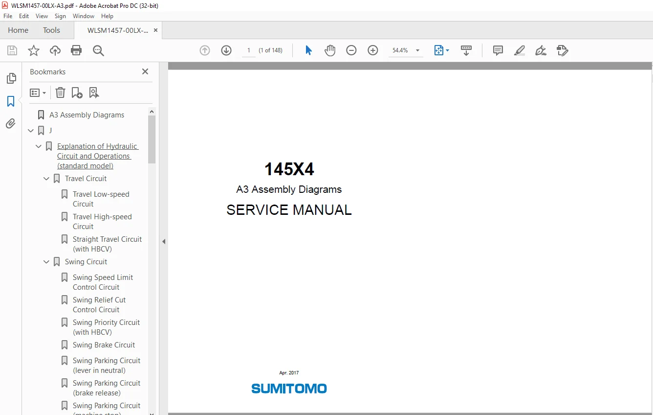
Linkbelt 145X4 A3 Assembly Diagrams SERVICE MANUAL – PDF DOWNLOAD
$28.95
Linkbelt 145X4 A3 Assembly Diagrams SERVICE MANUAL – PDF DOWNLOAD
Instant PDF Download
Available immediately
Save to Your Device
Download & keep forever
Antivirus Scanned
100% virus-free
Trusted Worldwide
175,000+ customers
Description
Linkbelt 145X4 A3 Assembly Diagrams SERVICE MANUAL – PDF DOWNLOAD
FILE DETAILS:
Linkbelt 145X4 A3 Assembly Diagrams SERVICE MANUAL – PDF DOWNLOAD
Language : English
Pages :148
Downloadable : Yes
File Type : PDF
IMAGES PREVIEW OF THE MANUAL:
TABLE OF CONTENTS:
Linkbelt 145X4 A3 Assembly Diagrams SERVICE MANUAL – PDF DOWNLOAD
A3 Assembly Diagrams 1
J 2
Explanation of Hydraulic Circuit and Operations (standard model) 5
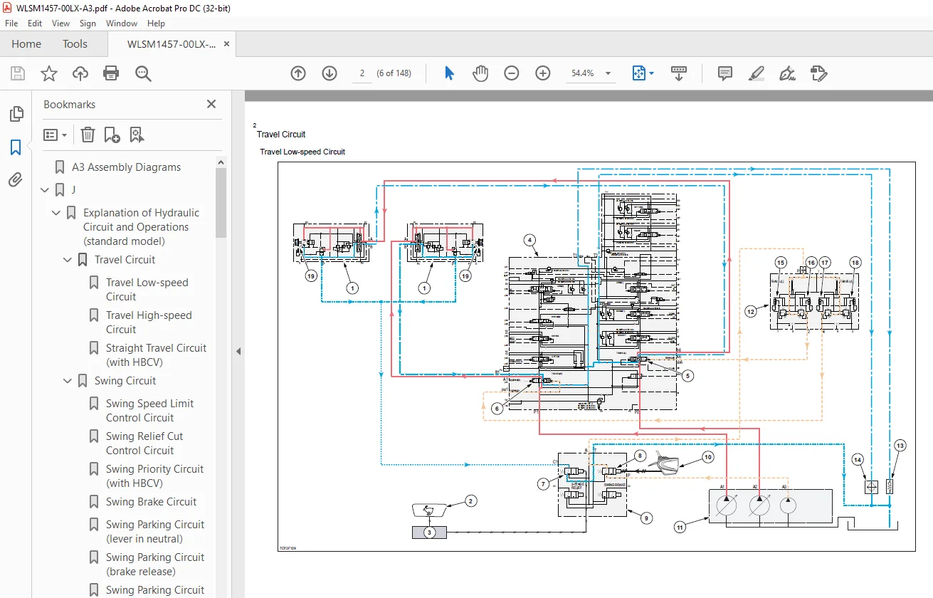
Travel Circuit 6
Travel Low-speed Circuit 6
Travel High-speed Circuit 8
Straight Travel Circuit (with HBCV) 10
Swing Circuit 12
Swing Speed Limit Control Circuit 12
Swing Relief Cut Control Circuit 14
Swing Priority Circuit (with HBCV) 16
Swing Brake Circuit 18
Swing Parking Circuit (lever in neutral) 20
Swing Parking Circuit (brake release) 22
Swing Parking Circuit (machine stop) 24
Boom Circuit 26
Boom-up Circuit (for independent operation) (with HBCV) 26
Boom-up Spool Stroke Control Circuit (boom-up + arm-in compound operation) (with HBCV) 28
Boom-down Regenerative Circuit (with HBCV) 30
Boom-down Load Holding Valve Circuit (with HBCV) 32
Arm Circuit 34
Arm-out Circuit (with HBCV) 34
Arm Semi-parallel 1 Circuit (for independent operation) (with HBCV) 36
Arm Semi-parallel 1 Circuit (for compound operation) (ex: arm-out + right swing operations) (with HBCV) 38
Arm Semi-parallel 1 Circuit (for compound operation) (ex: arm-in + boom-up operations) (with HBCV) 40
Arm-in Load Holding Valve Circuit (with HBCV) 42
Bucket Circuit 44
Bucket-open Circuit 44
Bucket-close Regenerative Circuit 46
Bucket-close Spool Stroke Control Circuit 48
Negative Control Circuit 50
Negative Control Circuit 50
Other Circuits 52
Cushion Circuit (arm-out operation) 54
Cushion Circuit (when stopping arm-out operation) 56
Cushion Circuit (arm-out → arm-in operation) 58
Heat Circuit (lever in neutral) 60
Auto Pressure Boost Circuit (arm in) 62
J 65
Explanation of Hydraulic Circuit and Operations (option) 67
Option Circuits 68
Single Breaker Circuit (pedal type) 68
Single Breaker Circuit (proportional control type) 70
Single Double-acting Circuit (proportional control type) (1 pump hydraulic fork) 72
Multi-purpose Circuit (proportional control type) (electromagnetic relief) (breaker) 74
Multi-purpose Circuit (proportional control type) (electromagnetic relief) (crusher) 76
2nd Option Circuit (proportional control type) (hydraulic rotation fork) 78
R 81
Electrical Connector Wiring Diagram 83
Frame Main Harness 84
Control Valve Harness 86
SCR Harness 88
Light Harness (boom light) 90
Light Harness (cab light) 92
Cab Light Harness (with guard) 94
Cab Main Harness 96
Indicator Jumper 98
Indicator Jumper100
Jumper Harness102
Console Harness104
GPS Computer Harness106
GPS Harness108
Computer S Harness110
Feed Pump Harness112
Relief Valve Harness114
WAVES Harness116
Camera Harness118
Camera Harness [500 mm (19685 in)]120
Camera Harness [800 mm (31496 in)]122
Quick Coupler Harness124
Option Harness (pedal)126
Option Harness (proportional control)128
2nd Option Harness (proportional control)130
R133
Electrical Parts and Wiring Assembly Diagram135
Frame (main unit right side, main unit center section)136
Frame (main unit left side)138
Engine and Pump140
Battery142
Cab 1144
Cab 2146
S.M 2/1/25