Linkbelt 210LX Excavator Service Manual 1032 – PDF DOWNLOAD
Original price was: $78.95.$29.95Current price is: $29.95.
Linkbelt 210LX Excavator Service Manual 1032 – PDF DOWNLOAD
Description
Linkbelt 210LX Excavator Service Manual 1032 – PDF DOWNLOAD
FILE DETAILS:
Linkbelt 210LX Excavator Service Manual 1032 – PDF DOWNLOAD
Language : English
Pages : 600
Downloadable : Yes
File Type : PDF
Size: 102 MB
IMAGES PREVIEW OF THE MANUAL:
Contact us: [email protected]
https://vimeo.com/771022980
DESCRIPTION:
Linkbelt 210LX Excavator Service Manual 1032 – PDF DOWNLOAD
GENERAL INFORMATION:
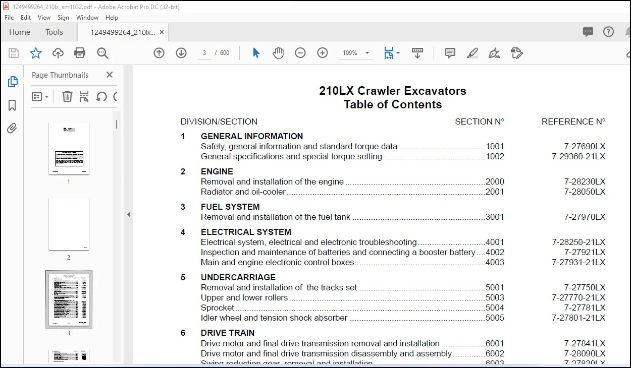
TABLE OF CONTENTS:
Linkbelt 210LX Excavator Service Manual 1032 – PDF DOWNLOAD
6004 pdf 0
Description 4 47
4001 pdf 0
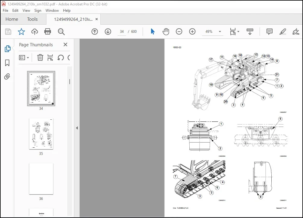
General Location of Components (Outside the Cab) 6 0
Relays and Main Fuses (Battery Compartment) 8 0
General Location of Components (Inside the Cab) 9 0
Fuse Box 11 0
Instrument Panel 12 0
H/S/L Mode Control 17 0
Automatic Mode Control 18 0
Acceleration Control 19 0
Control of Engine Return to Idle (Automatic/Manual) 20 0
Auxiliary Mode Control 21 0
Automatic Engine Pre-heat 22 0
Automatic Engine Warm-up 25 0
3) Diagram showing times 26 0
Idle Control by Battery Voltage and Coolant Temperature 27 0
Engine Emergency Stop 29 0
Emergency Mode 31 0
Lockout Functions 33 0
Power Up 34 0
Swing Brake 35 0
Travel Speed 39 0
Travel Alarm 42 0
Supply Cut-Off Delayed 43 0
Protection by Power Transistor 44 0
Water Temperature Gauge 44 0
Hydraulic Oil Temperature Gauge 46 0
Fuel Level 47 0
Engine Fuel Injection Pump Electronic Regulator 48 0
Access to Control Screens 50 0
Machine Condition 51 0
Diagnostic Code 55 0
Machine History 58 0
Reset 61 0
Message Display 64 0
Prior Inspections 68 0
Reading the Organization Charts 69 0
Procedures 70 0
Fuel 71 0
Add Coolant Solution 72 0
Low Engine Oil Pressure 73 0
Overheating 74 0
Battery Charge Circuit Defective 77 0
Electrical System Troubleshooting 79 0
Translation 83 0
5001 pdf 0
Description 4 0
Checking pin and bushing wear 12 0
5005 pdf 0
Description 8 0
Reconditioning 8 0
Description 14 0
Description 16 0
Removal 16 0
Notes 130
6003 pdf 0
Removal 3 0
Installation 4 0
8003 pdf 0
Removal and installation 4 0
Removal and installation 9 0
Removal and installation 11 0
Notes 0
8005 pdf 0
Description 3 0
Description 9 0
8006 pdf 0
Removal and installation 3 0
8008 pdf 0
Notes 36
8012 pdf 0
Boom cylinder description 4 0
Arm cylinder description 6 0
Bucket cylinder description 8 0
8014 pdf 0
NOTES 0
9003 pdf 0
Removal 4 0
Installation 4 0
Shimming the bucket 6 0
Removal 8 0
Installation 8 0
Removal 11 0
Installation 12 0
4001 pdf 0
General Location of Components (Outside the Cab) 6 0
Relays and Main Fuses (Battery Compartment) 8 0
General Location of Components (Inside the Cab) 9 0
Fuse Box 11 0
Instrument Panel 12 0
H/S/L Mode Control 17 0
Automatic Mode Control 18 0
Acceleration Control 19 0
Control of Engine Return to Idle (Automatic/Manual) 20 0
Auxiliary Mode Control 21 0
Automatic Engine Pre-heat 22 0
Automatic Engine Warm-up 25 0
3) Diagram showing times 26 0
Idle Control by Battery Voltage and Coolant Temperature 27 0
Engine Emergency Stop 29 0
Emergency Mode 31 0
Lockout Functions 33 0
Power Up 34 0
Swing Brake 35 0
Travel Speed 39 0
Travel Alarm 42 0
Supply Cut-Off Delayed 43 0
Protection by Power Transistor 44 0
Water Temperature Gauge 44 0
Hydraulic Oil Temperature Gauge 46 0
Fuel Level 47 0
Engine Fuel Injection Pump Electronic Regulator 48 0
Access to Control Screens 50 0
Machine Condition 51 0
Diagnostic Code 55 0
Machine History 58 0
Reset 61 0
Message Display 64 0
Prior Inspections 68 0
Reading the Organization Charts 69 0
Procedures 70 0
Fuel 71 0
Add Coolant Solution 72 0
Low Engine Oil Pressure 73 0
Overheating 74 0
Battery Charge Circuit Defective 77 0
Electrical System Troubleshooting 79 0
Translation 83 0
5001 pdf 0
Description 4 0
Checking pin and bushing wear 12 0
5005 pdf 0
Description 8 0
Reconditioning 8 0
Description 14 0
Description 16 0
Removal 16 0
Notes 130
6003 pdf 0
Removal 3 0
Installation 4 0
6004 pdf 0
Description 4 47
8003 pdf 0
Removal and installation 4 0
Removal and installation 9 0
Removal and installation 11 0
Notes 0
8005 pdf 0
Description 3 0
Description 9 0
8006 pdf 0
Removal and installation 3 0
8008 pdf 0
Notes 36
8012 pdf 0
Boom cylinder description 4 0
Arm cylinder description 6 0
Bucket cylinder description 8 0
8014 pdf 0
NOTES 0
9003 pdf 0
Removal 4 0
Installation 4 0
Shimming the bucket 6 0
Removal 8 0
Installation 8 0
Removal 11 0
Installation 12 0
PLEASE NOTE:
- This is the SAME MANUAL used by the dealerships to diagnose your vehicle
- No waiting for couriers / posts as this is a PDF manual and you can download it within 2 minutes time once you make the payment.
- Your payment is all safe and the delivery of the manual is INSTANT – You will be taken to the DOWNLOAD PAGE.
- So have no hesitations whatsoever and write to us about any queries you may have : heydownloadss @gmail.com
S.V