Linkbelt 240LX Crawler Excavators Service Manual 1033 – PDF DOWNLOAD
$31.95
Linkbelt 240LX Crawler Excavators Service Manual 1033 – PDF DOWNLOAD
Description
Linkbelt 240LX Crawler Excavators Service Manual 1033 – PDF DOWNLOAD
FILE DETAILS:
Linkbelt 240LX Crawler Excavators Service Manual 1033 – PDF DOWNLOAD
Language : English
Pages : 598
Downloadable : Yes
File Type : PDF
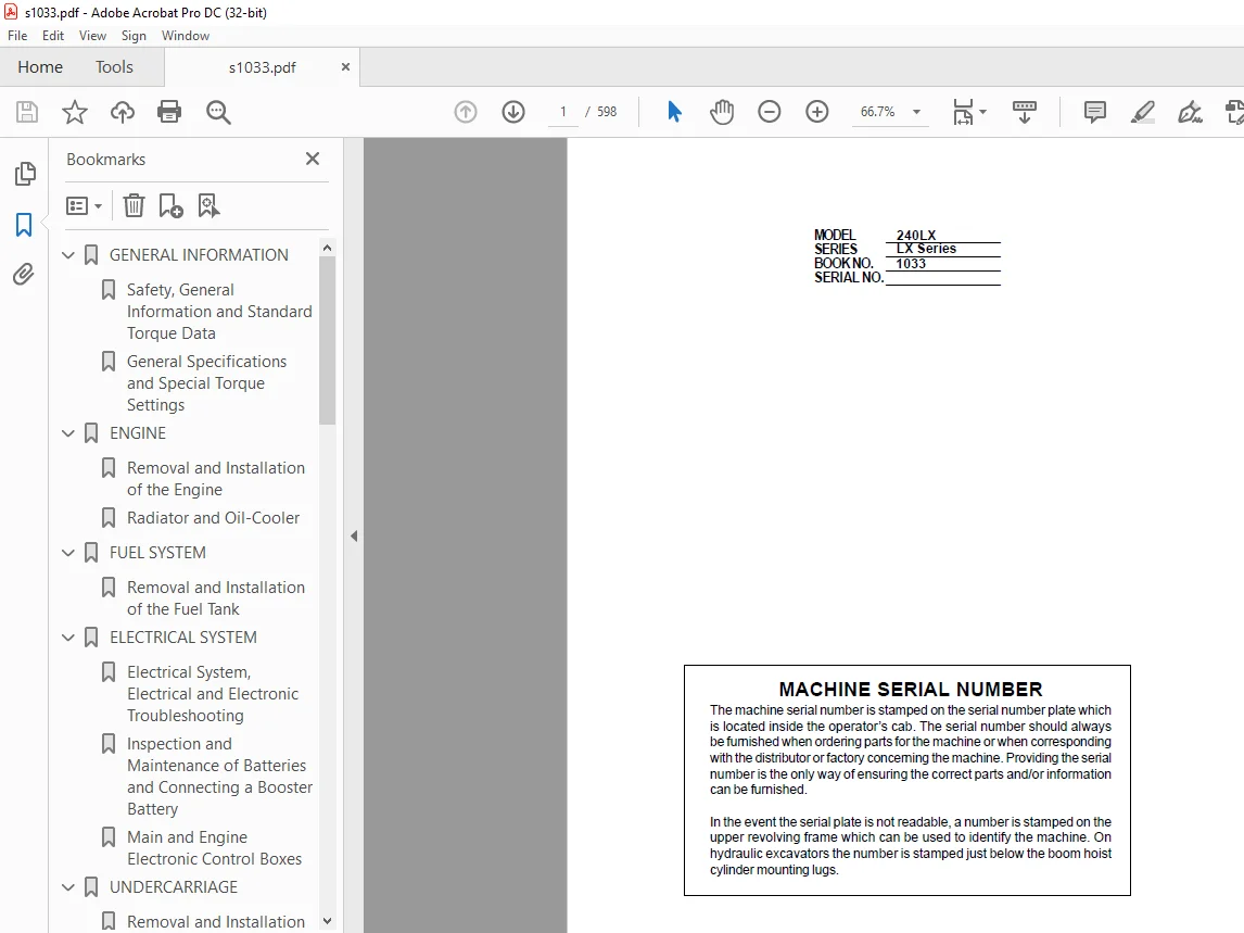
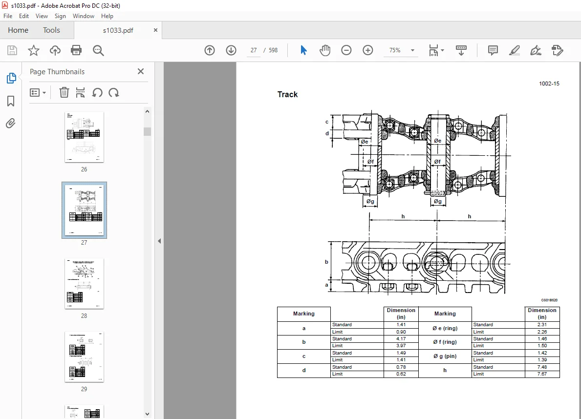
IMAGES PREVIEW OF THE MANUAL:
DESCRIPTION:
Linkbelt 240LX Crawler Excavators Service Manual 1033 – PDF DOWNLOAD
GENERAL INFORMATION
Cleaning
Clean all metal parts except bearings, in a suitable cleaning solvent or by steam cleaning. Do not use caustic soda for steam cleaning. After cleaning, dry and put oil on all parts. Clean oil passages with compressed air. Clean bearings in a suitable cleaning solvent. Dry the bearings completely and put oil on the bearings.
Inspection
Check all parts when the parts are disassembled. Replace all parts that have wear or damage. Small scoring or grooves can be removed with a hone or crocus cloth. Complete a visual inspection for indications of wear, pitting and the replacement of parts necessary to prevent early failures.
Bearings
Check bearings for easy action. If bearings have a loose fit or rough action, replace the bearing. Wash bearings with a suitable cleaning solvent and permit to air dry. DO NOT DRY BEARINGS WITH COMPRESSED AIR.
Needle Bearings
Before you press needle bearings in a bore always remove any metal protrusions in the bore or edge of the bore. Before you press bearings into position, put petroleum jelly on the inside and outside diameter of the bearings.
Gears
Check all gears for wear and damage. Replace gears that have wear or damage.
Oil Seals, O-rings and Gaskets
Always install new oil seals, O-rings and gaskets. Put petroleum jelly on seals and O-rings.
Shafts
Check all shafts that have wear or damage. Check the bearing and oil seal surfaces of the shafts for damage.
Service Parts
Always install genuine Link-Belt service parts. When ordering refer to the Parts Catalog for the correct part number of the genuine Link-Belt replacement items. Failures due to the use of other than genuine Link- Belt replacement parts are not covered by warranty.
Lubrication
Only use the oils and lubricants specified in the Operator’s or Service Manuals. Failures due to the use of non-specified oils and lubricants are not covered by warranty.
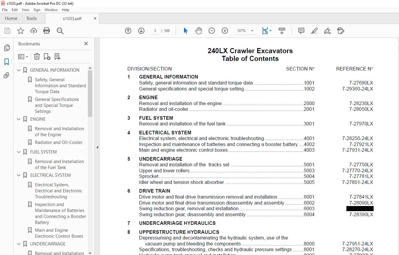
TABLE OF CONTENTS:
Linkbelt 240LX Crawler Excavators Service Manual 1033 – PDF DOWNLOAD
GENERAL INFORMATION.............................................................  5
	Safety, General Information and Standard Torque Data........................  5
	General Specifications and Special Torque Settings.......................... 13
ENGINE.......................................................................... 37
	Removal and Installation of the Engine...................................... 37
	Radiator and Oil-Cooler..................................................... 43
FUEL SYSTEM..................................................................... 51
	Removal and Installation of the Fuel Tank................................... 51
ELECTRICAL SYSTEM............................................................... 57
	Electrical System, Electrical and Electronic Troubleshooting................ 57
	Inspection and Maintenance of Batteries and Connecting a Booster Battery....147
	Main and Engine Electronic Control Boxes....................................157
UNDERCARRIAGE...................................................................161
	Removal and Installation of the Tracks Set..................................161
	Upper and Lower Rollers.....................................................173
	Sprocket....................................................................191
	Idler Wheel and Tension Shock Absorber......................................195
DRIVE TRAIN.....................................................................235
	Drive Motor and Final Drive Transmission Removal and Installation...........235
	Drive Motor and Final Drive Transmission Disassembly and Assembly...........241
	Swing Reduction Gear, Disassembly and Assembly..............................255
UPPERSTRUCTURE HYDRAULICS.......................................................267
	Depressurising and Decontaminating the Hydraulic System.....................267
	Specifications, Troubleshooting, Checks and Hydraulic Pressure Settings.....277
	Hydraulic Sump Tank Removal and Installation................................305
	Main and Pilot Pumps, Removal and Installation..............................311
	Main Hydraulic Control Valve, Removal and Installation......................323
	Attachment Cylinders, Removal and Installation..............................329
	Rotating Joint, Removal and Installation....................................349
	Pilot Blocks, Removal and Installation......................................353
	Free Swing Disassembly and Assembly.........................................369
	Main Hydraulic Pump, Disassembly and Assembly...............................375
	Main Hydraulic Control Valve, Disassembly and Assembly......................389
	Attachment Cylinders, Disassembly and Assembly..............................407
	Hand Joystick Control, Disassembly and Assembly.............................433
	Foot Joystick Control, Disassembly and Assembly.............................445
	Six Stack Solenoid Valve, Disassembly and Assembly..........................461
	Cushion Control, Disassembly and Assembly...................................467
	Hose Burst Check Valve......................................................475
	Rotating Joint, Disassembly and Assembly....................................487
	Swing Motor, Disassembly and Assembly.......................................495
	Hydraulic Functions.........................................................511
UPPERSTRUCTURE..................................................................545
	Upperstructure, Turntable and Counterweight.................................545
	Boom, Arm and Bucket........................................................559
	Seat and Safety Belt........................................................571
	Cab and Cab Equipment.......................................................579
	Large Format Hydraulic and Electrical Schematics............................595
Questions? Email us: [email protected]
https://vimeo.com/892122191?share=copy
S.S