Linkbelt 245X4 DZ 245X4 LC Excavator Service Manual WLSM2457-07LX – PDF DOWNLOAD
Original price was: $75.95.$28.95Current price is: $28.95.
Linkbelt 245X4 DZ 245X4 LC Excavator Service Manual WLSM2457-07LX – PDF DOWNLOAD
Description
Linkbelt 245X4 DZ 245X4 LC Excavator Service Manual WLSM2457-07LX – PDF DOWNLOAD
FILE DETAILS:
Linkbelt 245X4 DZ 245X4 LC Excavator Service Manual WLSM2457-07LX – PDF DOWNLOAD
Language : English
Pages : 2155
Downloadable : Yes
File Type : PDF
Size: 115 MB
IMAGES PREVIEW OF THE MANUAL:
Customer Support: [email protected]
https://vimeo.com/770726402
DESCRIPTION:
Linkbelt 245X4 DZ 245X4 LC Excavator Service Manual WLSM2457-07LX – PDF DOWNLOAD
General Information:
Cleaning:
Clean the metal parts with a cleaning fluid or steamer that meets standards. (except for the bearing) After cleaning the parts, let them dry well and inject oil into all parts. Inject oil into the bearing after letting it dry.
Inspection:
When disassembling parts, inspect all the parts. Replace any worn or damaged parts. Inspect them thoroughly to prevent early failures.
Bearing:
If the bearing is loose, replace it. Install the bearing after air drying it.
Needle bearing:
- When inserting the needle bearing, be careful not to scratch it.
- Inject grease into the location where the needle bearing is to be inserted.
Gear:
Check for any wear or damage.
Oil seals, O-rings, gaskets:
- Always install new oil seals, O-rings, and gaskets.
- Inject grease into the locations where oil seals and O-rings are to be inserted.
Shaft:
- Check for any wear or damage.
- Check the oil seal on the bearing and damaged shaft.
Service parts:
Install genuine LBX Link-Belt service parts. When ordering parts, see the parts catalog that has genuine LBX Link-Belt part numbers listed. Any failures caused by installing a nongenuine part are not covered by the warranty.
Lubrication (fuel, hydraulic oil):
Use oils from specified manufacturers or the ones specified in the operator’s manual or Service Manual. Any failures caused by using other fuel or hydraulic oil than specified are not covered by the warranty.
TABLE OF CONTENTS:
Linkbelt 245X4 DZ 245X4 LC Excavator Service Manual WLSM2457-07LX – PDF DOWNLOAD
Excavator 1
SAFETY 9
Safety, general information and standard torque data 12
General Information 13
Safety 13
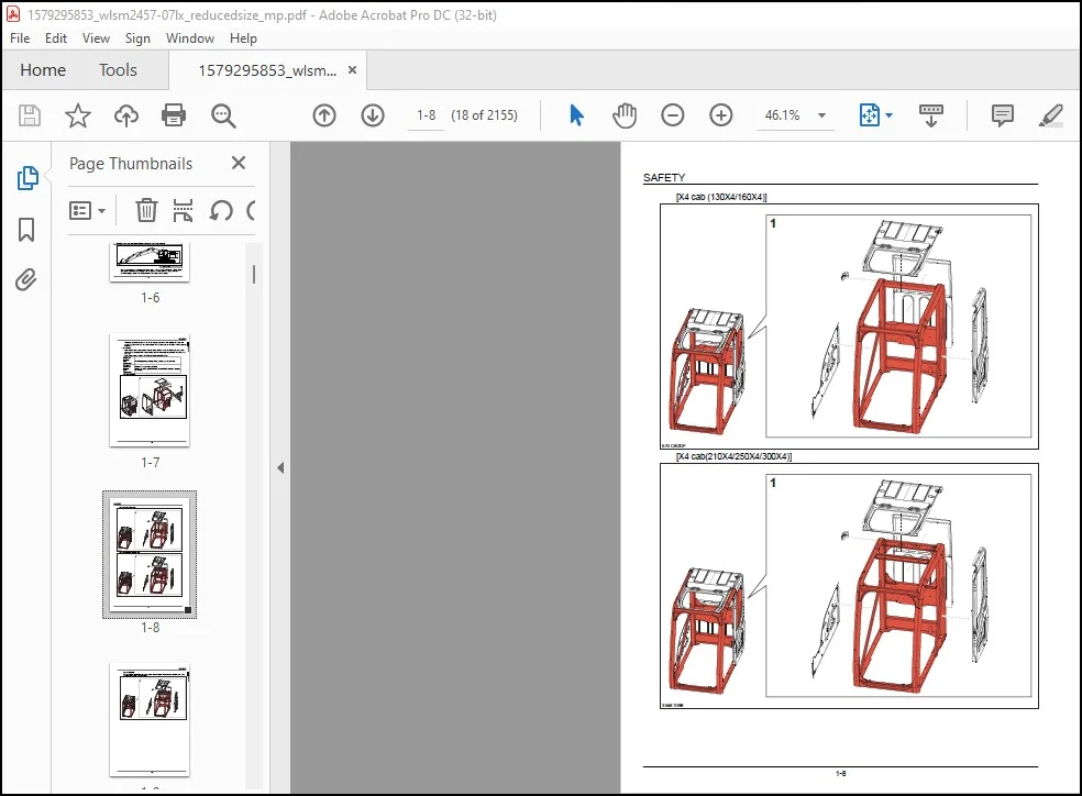
ROPS 16
ROPS Judgment 16
Standard Torque Data For Cap Screws And Nuts 21
Bolt and Nut Tightening 21
Removal of Under Cover 22
Protection of Electric/Electronics System During Charging or Welding 25
A LOWER 27
Main Equipment Table 31
Lower Component 31
Travel Unit 31
Take-up roller 31
Upper Roller 31
Lower Roller 31
Recoil Spring 31
Shoe 32
Shoe 32
Center Joint 33
Center Joint (Blade) 33
Main Equipment Structure and Operation Explanation 34
Travel Motor 34
Travel motor operation explanation 34
Explanation of Component Device Operation 34
Double Counter Balance Valve 34
Crossover Relief Valve 40
Automatic 2-speed Switchover Mechanism 42
Parking Brake Function 47
Piston Motor 48
Reduction Gear 48
Port Diagram 50
Travel Motor 50
Center Joint 50
Center Joint (Blade) 51
Basic Functions 52
Travel Speed Selection 52
Travel Alarm 53
Removal and Installation of Track 54
Removal and Installation of Shoe Assembly 54
Removal of Shoe Assembly 54
Installation of Shoe Assembly 56
Removal and Installation of Shoe Plate 57
Removal of Shoe Plate 57
Installation of Shoe Plate 58
Precautions for Shoe Bolt Installation 58
Removal and Installation of Roller 60
Removal and Installation of Upper Roller 60
Removal of Upper Roller 60
Installation of Upper Roller 61
Assembly and Disassembly of Upper Roller 62
Configuration Diagram 62
Dimension Diagram 63
Jig Dimension Diagram 63
Disassembly Procedures 64
Assembly Procedures 66
Removal and Installation of Lower Roller 68
Removal of Lower Roller 69
Installation of Lower Roller 69
Assembly and Disassembly of Lower Roller 71
Configuration Diagram 71
Dimension Diagram 72
Jig Dimension Diagram 72
Disassembly Procedures 72
Assembly Procedures 75
Removal and Installation of Drive Sprocket 77
Removal of Drive Sprocket 77
Installation of Drive Sprocket 79
Removal and Installation of Take-up Roller 80
Removal of Take-up Roller 80
Installation of Take-up Roller 81
Assembly and Disassembly of Take-up Roller 82
Configuration Diagram 83
Dimension Diagram 83
Jig Dimension Diagram 84
Disassembly Procedures 84
Assembly Procedures 87
Removal and Installation of Grease Cylinder 90
Removal of Grease Cylinder 90
Installation of Grease Cylinder 91
Assembly and Disassembly of Tension Shock Absorber 92
Configuration Diagram 92
Dimension Diagram 93
Jig Dimension Diagram 93
Disassembly procedures 93
Assembly procedures 94
Removal and Installation of Center Joint 96
Removal of Center Joint 96
Installation of Center Joint 97
Assembly and Disassembly of Center Joint 98
Configuration Diagram 99
Dimension Diagram 100
Dimension Diagram (Blade) 101
Jig Dimension Diagram 102
Disassembly Procedures 102
Assembly Procedures 103
Removal and Installation of Travel Motor 106
Removal of Travel Motor 106
Installation of Travel Motor 108
Assembly and Disassembly of Travel Motor 111
Tools for Assembly and Disassembly 111
Standard Tools 111
Secondary Materials 113
Special Tool (jig) 115
Measurement Device 115
Motor Disassembly Procedures 116
Precautions before Motor Disassembly 116
Tightening Torque 117
Disassembly Procedure 118
Maintenance Standards 127
Motor Parts Maintenance Standards 127
Reduction Gear Parts Maintenance Standards 129
Motor Assembly Procedures 132
Precautions before Motor Assembly 132
Assembly Procedure 132
Motor Installation 146
Inspection 146
Hydraulic Oil and Gear Oil Filling 147
Initial Pre-conditioning Operation 148
Troubleshooting 149
Structural Diagram 158
Internal Structure Diagram 161
Part Table 163
Maintenance Standards 164
Drive sprocket 164
Take-up roller 165
Upper roller 166
Lower Roller 167
Track Shoe (Grouser Shoe) 168
Inspection Gauge 169
For Drive Sprocket 169
For Take-up Roller 169
For Upper Roller 170
For Lower Roller 170
Pressure Measurement and Adjustment Procedures 171
Main Pressure Measurement 171
B Travel Pressure Measurement 171
Drain Volume Measurement Procedures 172
Preparations 172
Travel Motor Drain Volume Measurement 172
Air Bleed Procedure 174
Travel Motor 174
B C SWING UNIT, COUNTERWEIGHT 175
Main Equipment Table 178
Upper Component 178
Swing Unit 178
Main Equipment Structure and Operation Explanation 179
Swing Motor 179
Swing Motor Operation Explanation 179
Hydraulic Motor Section 179
Valve Casing Section 180
Brake Section 181
Relief Valve Operation Explanation (relief valve model: KRD22EK10) 182
Swing Motor Internal Structure Diagram 184
Port Diagram 186
Swing Motor 186
Basic Functions 187
Swing brake 187
Swing Lock 188
Swing Speed Limit 189
Swing Relief Cut 191
Removal and Installation of Swing Unit 192
Removal of Swing Unit 192
Installation of Swing Unit 195
Assembly and Disassembly of Swing Motor 196
Troubleshooting 197
Maintenance Reference Table 199
Jig 200
Disassembling Instructions 203
Assembling Instructions 208
Swing Motor Internal Structure Diagram 218
Assembly and Disassembly of Swing Reduction Gear 220
Disassembly 220
Assembly 223
Jig 229
Swing Reduction Gear Internal Structure Diagram 230
Removal and Installation of Counterweight 231
Removal of Counterweight 231
Installation of Counterweight 234
Pressure Measurement and Adjustment Procedures 237
Main Pressure Measurement 237
C Swing Pressure Measurement 237
Drain Volume Measurement Procedures 238
Preparations 238
Swing Motor Drain Volume Measurement 238
Air Bleed Procedure 239
Swing motor 239
Check 239
H ENGINE 241
Main Equipment Table 249
Engine-related 249
Engine 249
Air Cleaner (double element) 249
Radiator 249
SCR 249
Basic Functions 250
Fuel Gauge 250
Coolant Temperature Gauge 252
SCR Gauge 254
Fuel Economy Gauge 259
Neutral start 260
Power-cut Delay 261
Preheat 262
Throttle 263
Throttle Volume Position Detection 264
Idle start 270
Auto Idle 271
One-touch Idle 272
Auto Warm-Up 273
Idle Shutdown 278
Idle up 279
Work Mode Control 280
Engine Emergency Stop 281
SCR RE-GEN 282
Inducement 288
Feed Pump Automatic Stop 293
Coolant Level Decrease 295
Air Filter Clogging 296
Fuel Filter Clogging 297
Battery Charge Abnormality 299
Horsepower Reduction Control (in Uplands) 300
Horsepower Reduction Control (at Engine Failure) 301
Main Data 303
Function, Structure, Operation 305
Function, structure, operation (SCR) 364
SCR Control System Inspection 394
Explanation of SCR Operation 395
Diagnosis for Each Symptom 397
Intermittent conditions of urea selective catalytic reduction system 397
Urea fluid consumption too high 399
Ammonia smell noticeable 400
White crystalline powder visible 400
Diagnosis for Each Symptom 402
Engine Start Problems 402
Engine Stalling 404
Engine Hunting, Rough Idling 406
Excess Amount of White Smoke in Exhaust Gas 407
Excess Amount of Black Smoke in Exhaust Gas 408
Abnormal Noise 408
High Fuel Consumption 409
High Oil Consumption 411
Engine Output Deficiency 411
Functional Inspection 414
Engine Compression Pressure Inspection 414
Fuel System Inspection 415
Lubrication system check 415
Air intake system inspection 416
Exhaust system inspection 416
Inspection of EGR Control System 416
Start System Inspection 417
Glow control system check 417
OBD system check 419
Inspection of the monitor warning light illumination circuit system 419
Inspection of the monitor warning light blinking circuit system 420
Inspection of the starter circuit system 421
Removal and Installation of Engine Assembly 422
Removal of Engine Assembly 422
Installation of Engine Assembly 427
Removal and Installation of Fuel Cooler, Engine Intercooler, Radiator, and Oil Cooler 428
Removal and Installation of Fuel Cooler 428
Removal of Fuel Cooler 428
Installation of Fuel Cooler 428
Removal and Installation of Engine Intercooler 428
Removal of Intercooler 429
Installation of Inter Cooler 430
Inspection of Intercooler 430
Removal and Installation of Radiator 430
Removal of Radiator 431
Installation of Radiator 434
Inspection of Radiator 434
Removal and Installation of Oil Cooler 435
Removal of Oil Cooler 435
Installation of Oil Cooler 437
Removal and Installation of Turbo Charger 438
Removal of Turbo Charger 438
Installation of Turbo Charger 440
Inspection of Turbo Charger 443
Removal and Installation of EGR Valve (if equipped) 445
Removal of EGR Valve 445
Installation of EGR Valve 447
Inspection of EGR Valve 451
Removal and Installation of Top Cover 452
Removal of Top Cover 452
Installation of Top Cover 453
Removal and Installation of SCR 454
Removal of SCR 454
Installation of SCR 455
Removal and installation of Silicon Controlled Rectifier Catalyst 456
Removal of Silicon Controlled Rectifier Catalyst 456
Installation of Silicon Controlled Rectifier Catalyst 457
Disassembly of Silicon Controlled Rectifier Catalyst 460
Assembly of Silicon Controlled Rectifier Catalyst 460
Inspection of Silicon Controlled Rectifier Catalyst 461
Removal and Installation of Cylinder Head Cover 462
Cylinder head cover Removal 462
Installation of Cylinder Head Cover 462
Removal and Installation of Cylinder Head 463
Removal of Cylinder Head 463
Disassembly of Cylinder Head 472
Assembly of Cylinder Head 476
Installation of Cylinder Head 483
Inspection 501
Removal and Installation of Cylinder Block 507
Removal of Cylinder Block 507
Installation of Cylinder Block 523
Inspection 558
Lubrication System 560
Removal and Installation of Oil Pan 560
Removal of Oil Pan 560
Installation of Oil Pan 560
Removal and Installation of Oil Level Switch 560
Removal of Oil Level Switch 560
Installation of Oil Level Switch 561
Removal and Installation of Oil Pump Assembly 561
Removal of Oil Pump Assembly 561
Disassembly of Oil Pump Assembly 574
Assembly of Oil Pump Assembly 574
Installation of Oil Pump Assembly 575
Inspection 599
Engine oil Inspection 600
Removal and Installation of Oil Port Cover 601
Removal of Oil Port Cover 601
Installation of Oil Port Cover 601
Cooling System 603
Removal and Installation of Water Pump Assembly 603
Removal of Water Pump Assembly 603
Installation of Water Pump Assembly 604
Inspection of Water Pump Assembly 608
Removal and Installation of Thermostat 608
Removal of Thermostat 608
Installation of Thermostat 609
Inspection 611
Inspection of Coolant 611
Inspection of Cooling Fan Belt 616
Removal and Installation of Overheat Switch 616
Removal of Overheat Switch 616
Installation of Overheat Switch 617
Induction System 618
Inspection of Air Cleaner Element 618
Exhaust System 619
Removal and installation of Oxidation Catalyst Assembly 619
Removal of Oxidation Catalyst Assembly 619
Installation of Oxidation Catalyst Assembly 620
Aux Emission Control Devices System 623
Removal and installation of Dosing Module 623
Removal of Dosing Module 623
Disassembly of Dosing Module 623
Assembly of Dosing Module 624
Installation of Dosing Module 624
Removal and installation of DEF Supply Module 626
Removal of DEF supply module 626
Disassembly of DEF Supply Module 627
Assembly of DEF Supply Module 627
Installation of DEF Supply Module 628
Removal and installation of Coolant Control Valve 630
Removal of Coolant Control Valve 630
Installation of Coolant Control Valve 631
Removal and installation of DEF Supply Module Filter 633
Removal of DEF Supply Module Filter 633
Installation of DEF Supply Module Filter 633
Removal and Installation of Exhaust Manifold 635
Removal of Exhaust Manifold 635
Installation of Exhaust Manifold 638
Inspection 644
Removal and Installation of Fuel Tank 645
Removal of Fuel Tank 645
Installation of fuel tank 648
Removal and Installation of Urea Pump 649
Removal of Urea Pump 649
Installation of Urea Pump 650
Removal and Installation of Urea Solution Tank 651
Removal of Urea Tank 651
Installation of Urea Solution Tank 652
Removal and Installation of Fuel Supply Pump 653
Removal of Fuel Supply Pump 653
Installation of Fuel Supply Pump 654
Removal and Installation of Common Rail Assembly 658
Removal of Common Rail Assembly 658
Installation of Common Rail Assembly 660
Removal and Installation of Injector 665
Removal of Injector 665
Installation of Injector 668
Removal and installation of Idle Gear 674
Removal of Idle Gear 674
Installation of Idle Gear 686
Inspection of Idle Gear 710
Removal and installation of Inlet Cover 712
Removal of Inlet Cover 712
Installation of Inlet Cover 716
Removal and installation of Crankshaft 726
Removal of Crankshaft 726
Installation of Crankshaft 741
Disassembly of Crankshaft 774
Assembly of Crankshaft 774
Inspection of Crankshaft 774
Removal and installation of Piston 779
Removal of Piston 779
Installation of Piston 789
Disassembly of Piston 809
Assembly of Piston 809
Inspection of Piston 811
Removal and installation of Camshaft 818
Removal of Camshaft 818
Installation of Camshaft 819
Disassembly of Camshaft 823
Assembly of Camshaft 824
Inspection of Camshaft 824
Removal and installation of Flywheel 826
Removal of Flywheel 826
Installation of Flywheel 827
Inspection of Flywheel 828
Removal and installation of Crankshaft Front Oil Seal 829
Removal of Crankshaft Front Oil Seal 829
Installation of Crankshaft Front Oil Seal 830
Removal and installation of Crankshaft Rear Oil Seal 833
Removal of Crankshaft Rear Oil Seal 833
Installation of Crankshaft Rear Oil Seal 834
Removal and installation of Rocker Arm Shaft 837
Removal of Rocker Arm Shaft 837
Installation of Rocker Arm Shaft 838
Disassembly of Rocker Arm Shaft 841
Assembly of Rocker Arm Shaft 841
Inspection of Rocker Arm Shaft 843
Removal and installation of Valve Spring 845
Removal of Valve Spring 845
Installation of Valve Spring 847
Inspection of Valve Spring 852
Removal and installation of Valve Stem Oil Seal 854
Removal of Valve Stem Oil Seal 854
Installation of Valve Stem Oil Seal 856
Removal and installation of Front Cover 863
Removal of Front Cover 863
Installation of Front Cover 865
Removal and installation of Intake Throttle Valve 871
Removal of Intake Throttle Valve 871
Installation of Intake Throttle Valve 871
Removal and Installation of Starter Motor 872
Removal of Starter Motor 872
Installation of Starter Motor 872
Disassembly of Starter Motor 873
Assembly of Starter Motor 874
Inspection of Starter Motor 875
Removal and Installation of Alternator 879
Removal of Alternator 879
Installation of Alternator 880
Disassembly of Alternator 880
Assembly of Alternator 881
Inspection of Alternator 882
Removal and Installation of Glow Plug 886
Removal of Glow Plug 886
Installation of Glow Plug 886
Glow plug Inspection 886
Removal and Installation of Suction Control Valve 887
Removal of Suction Control Valve 887
Installation of Suction Control Valve 887
Removal and installation of Fuel Filter 890
Removal of Fuel Filter 890
Installation of Fuel Filter 890
Removal and installation of Relief Valve 893
Removal of Relief Valve 893
Installation of Relief Valve 893
Removal and installation of Fuel Filter Element 896
Removal of Fuel Filter Element 896
Installation of Fuel Filter Element 897
Removal and Installation of Fuel filter pressure 900
Fuel filter pressure sensor Removal 900
Fuel filter pressure sensor Installation 900
Removal and Installation of Engine coolant temperature sensor 901
Engine coolant temperature sensor Removal 901
Engine coolant temperature sensor Installation 901
Engine coolant temperature sensor Inspection 901
Removal and Installation of CKP sensor 902
CKP sensor Removal 902
CKP sensor Installation 902
CKP sensor Inspection 902
Removal and Installation of CMP sensor 903
CMP sensor Removal 903
CMP sensor Installation 903
CMP sensor Inspection 903
Removal and Installation of Oil pressure sensor 904
Oil pressure sensor Removal 904
Oil pressure sensor Installation 904
Oil pressure sensor Inspection 904
Removal and installation of Pressure Sensor/Boost Temperature Sensor 905
Removal of Pressure Sensor/Boost Temperature Sensor 905
Installation of Pressure Sensor/Boost Temperature Sensor 905
Inspection of Pressure Sensor/Boost Temperature Sensor 905
Removal and Installation of IMT sensor 906
Removal of IMT sensor 906
Installation of IMT sensor 906
Removal and installation of Charge Air Cooler Temperature Sensor 1 907
Removal of Charge Air Cooler Temperature Sensor 1 907
Installation of Charge Air Cooler Temperature Sensor 1 907
Inspection of Charge Air Cooler Temperature Sensor 1 907
Sampling Procedure 908
Sampling of Engine Oil 908
Removal and Installation of Exhaust gas temperature sensor 909
Removal of Exhaust gas temperature sensor 909
Installation of Exhaust gas temperature sensor 909
Inspection of Exhaust gas temperature sensor 910
Removal and installation of EGR Gas Temperature Sensor 1 911
Removal of EGR Gas Temperature Sensor 1 911
Installation of EGR Gas Temperature Sensor 1 911
Inspection of EGR Gas Temperature Sensor 1 911
Removal and installation of EGR Gas Temperature Sensor 2 912
Removal of EGR Gas Temperature Sensor 2 912
Installation of EGR Gas Temperature Sensor 2 912
Inspection of EGR Gas Temperature Sensor 2 913
Removal and installation of NOx Sensor 914
Removal of NOx Sensor 914
Installation of NOx Sensor 914
Removal and Installation of Exhaust gas temperature sensor 3 917
Removal of Exhaust gas temperature sensor 3 917
Installation of Exhaust gas temperature sensor 3 917
Removal and installation of DEF Sensor 919
Removal of DEF Sensor 919
Installation of DEF Sensor 919
Engine-related Diagnostic Trouble Code List 920
Engine-side Trouble 929
ECM Trouble 929
DTC P0016 Crankshaft Position – Camshaft Position Correlation Error 929
DTC P0045 Turbocharger Boost Control VNT Error 930
DTC P0087 Fuel Rail/System Pressure – Too Low 932
DTC P0089 Fuel Pressure Regulator Performance 935
DTC P0091 Fuel Pressure Regulator Control Circuit Low 936
DTC P0092 Fuel Pressure Regulator Control Circuit High 937
DTC P0097 Intake Air Temperature (IAT) Sensor 2 Circuit Low Voltage 939
DTC P0098 Intake Air Temperature (IAT) Sensor 2 Circuit High Voltage 940
DTC P0102 Mass Air Flow Sensor Circuit Low Input 941
DTC P0103 Mass Air Flow Sensor Circuit High Input 942
DTC P0112 Intake Air Temperature Sensor Circuit Low 943
DTC P0113 Intake Air Temperature Sensor Circuit High 944
DTC P0117 Engine Coolant Temperature Sensor Circuit Low 946
DTC P0118 Engine Coolant Temperature Sensor Circuit High 947
DTC P0122 Throttle Position Sensor Circuit Low 948
DTC P0123 Throttle Position Sensor Circuit High 949
DTC P0182 Fuel Temperature Sensor Circuit Low 950
DTC P0183 Fuel Temperature Sensor Circuit High 951
DTC P0192 Fuel Rail Pressure Sensor Circuit Low 953
DTC P0193 Fuel Rail Pressure Sensor Circuit High 954
DTC P0201 Injector Circuit Open – Cylinder 1 955
DTC P0202 Injector Circuit Open – Cylinder 2 956
DTC P0203 Injector Circuit Open – Cylinder 3 957
DTC P0204 Injector Circuit Open – Cylinder 4 958
DTC P0217 Engine Coolant Over Temperature Condition 959
DTC P0219 Engine Overspeed Condition 960
DTC P0234 Turbocharger Overboost Condition 961
DTC P0237 Turbo Charger Boost Sensor Circuit Low 963
DTC P0238 Turbo Charger Boost Sensor Circuit High 964
DTC P0335 Crankshaft Position Sensor Circuit 965
DTC P0336 Crankshaft Position Sensor Circuit Range/Performance 966
DTC P0340 Camshaft Position Sensor Circuit 967
DTC P0380 Glow Relay Circuit Error 969
DTC P0401 EGR Flow Insufficient Detected 970
DTC P0404 EGR Control Circuit Range/Performance 971
DTC P0409 EGR Sensor Circuit 972
DTC P041C EGR Cooler Outlet 1 Temp Sensor Circuit Low 974
DTC P041D EGR Cooler Outlet 1 Temp Sensor Circuit High 975
DTC P0427 Catalyst Temperature Sensor Circuit Low Sensor 1 976
DTC P0428 Catalyst Temperature Sensor Circuit High Sensor 1 977
DTC P042C Catalyst Temperature Sensor Circuit Low Sensor 2 979
DTC P042D Catalyst Temperature Sensor Circuit High Sensor 2 980
DTC P0522 Engine Oil Pressure Sensor Circuit Low Input 981
DTC P0523 Engine Oil Pressure Sensor Circuit High Input 982
DTC P0545 EGR Cooler Inlet 1 Temp Sensor Circuit Low 983
DTC P0546 EGR Cooler Inlet 1Temp Sensor Circuit High 984
DTC P0560 12 Volt Circuit Error 986
DTC P0563 System Voltage High 987
DTC P0601 Internal Control Module Memory Check Sum Error 987
DTC P0602 Internal Control Module QR Code Error 988
DTC P0604 Internal Control Module RAM Error 989
DTC P0606 Internal Control Module CPU Error 989
DTC P060A Internal Control Module CPU IC Error 990
DTC P060C Internal Control Module A/D Processing Performance 990
DTC P0615 Starter Relay Circuit Error 991
DTC P0638 Throttle Actuator Control Range/Performance 992
DTC P0685 ECM Power Relay Control Circuit Open 993
DTC P0687 ECM Power Relay Control Circuit High 994
DTC P06A6 Sensor Reference Voltage 1 Circuit 995
DTC P06A7 Sensor Reference Voltage 2 Circuit 996
DTC P06A8 Sensor Reference Voltage 3 Circuit 997
DTC P06A9 Sensor Reference Voltage 4 Circuit 998
DTC P06AF Torque Management System – Forced Engine Shutdown 1000
DTC P06D5 Sensor Reference Voltage 5 Circuit 1000
DTC P1076 Charge Air Cooler (CAC) Temperature Sensor 1 Circuit Low Voltage 1001
DTC P1077 Charge Air Cooler (CAC) Temperature Sensor 1 Circuit High Voltage 1002
DTC P1093 Fuel Rail Pressure Too Low 1003
DTC P1097 Compressor Outlet Temperature Sensor Circuit High 1006
DTC P1098 Compressor Outlet Temperature Sensor Circuit High 1007
DTC P1236 Charge Air Cooler Performance Failure 1009
DTC P1261 Injector Positive Voltage Control Circuit Group 1 1010
DTC P1262 Injector Positive Voltage Control Circuit Group 2 1010
DTC P1404 EGR Position Fault 1011
DTC P1606 SW-IC Internal failure 1012
DTC P160B AD-IC Failure Error 1012
DTC P160C AD-IC2 Failure Error 1013
DTC P1621 Control Module Long Term Memory Performance 1013
DTC P1622 Control Module Long Term Memory Hardware 1014
DTC P1669 DPD Lamp Control Circuit 1015
DTC P204F SCR System Error (No Inducement) 1016
DTC P207F Urea Fluid Concentration Too Low 1017
DTC P20C9 SCR System Error 1017
DTC P2122 Pedal Position Sensor 1 Circuit Low Input 1018
DTC P2123 Pedal Position Sensor 1 Circuit High Input 1019
DTC P2127 Pedal Position Sensor 2 Circuit Low Input 1020
DTC P2128 Pedal Position Sensor 2 Circuit High Input 1021
DTC P2138 Pedal Position Sensor 1 – 2 Voltage Correlation 1022
DTC P2146 Fuel Injector Group 1 Supply Voltage Circuit 1023
DTC P2149 Fuel Injector Group 2 Supply Voltage Circuit 1024
DTC P2228 Barometric Pressure Sensor Circuit Low 1026
DTC P2229 Barometric Pressure Sensor Circuit High 1026
DTC P2457 Exhaust Gas Recirculation (EGR) Cooling System Performance 1027
DTC P2458 Purge time Out Error 1028
DTC P2BA7 Urea Fluid Quantity Too Low 1028
DTC P2BAA SCR System Error (Inducement, No Purge) 1029
DTC P3093 Fuel Rail Pressure Too Low 1029
DTC U0001 CAN Bus Error (ISO-CAN) 1032
DTC U0073 Control Module Communication Bus Off 1034
DTC U0101 Lost Communication With CAN 1035
DTC U010E Lost Communications With Dosing Control Module 1036
DTC U0110 Lost Communication With VNT System 1037
DTC U2106 Lost CAN Communications With Wheel Loader Transmission Control System 1038
DTC U0411 Lost CAN Communications With VNT Control Module 1039
DCU Trouble 1039
Diagnostic Trouble Code_P0607: Control Module Characteristic Abnormality 1039
Diagnostic trouble code_P060B: Control Module A/D Conversion Processing Device Abnormality 1040
Diagnostic trouble code_P062F: Control Module EEPROM Abnormality 1041
Diagnostic trouble code_P0641: Sensor Reference Voltage Abnormality 1042
Diagnostic trouble code_P0658: Actuator Supply Power Feed System Abnormality 1043
Diagnostic trouble code_P0659: Actuator Supply Power Feed System Abnormality 1045
Diagnostic trouble code_P1462: Urea Solution Quality Sensor Time-Out Abnormality 1046
Diagnostic trouble code_P1464: Main Relay Abnormality (Early OPEN Error/Sticking Error of Main Relay) 1047
Diagnostic trouble code_P1468: Urea Solution Injection Control Module (DCM) High Temperature Abnormality 1048
Diagnostic trouble code_P1491: Urea Solution High Pressure Abnormality 1049
Diagnostic trouble code_P1493: Urea Solution Injection Control Module (DCM) Screwdriver High Temperature Abnormality 1050
Diagnostic trouble code_P149C: Urea Solution Reducing Pressure Abnormality 1051
DTC P149D Urea Fluid Tank Overtemperature 1052
Diagnostic trouble code_P2000: Cleaning Ratio Abnormality 1054
Diagnostic trouble code_P203B: Urea Solution Tank Level Sensor 1055
Diagnostic trouble code_P203C: Urea Solution Tank Level Sensor Low Voltage Potential 1057
Diagnostic trouble code_P203D: Urea Solution Tank Level Sensor High Voltage Potential 1058
Diagnostic trouble code_P2048: Urea Solution Injector System Low Voltage Potential 1059
Diagnostic trouble code_P2049: Urea Solution Injector System High Voltage Potential 1060
Diagnostic trouble code_P204B: Urea Solution Pressure Sensor System Characteristic Abnormality 1061
Diagnostic trouble code_P204C: Urea Solution Pressure Sensor System Low Voltage Potential 1062
Diagnostic trouble code_P204D: Urea Solution Pressure Sensor System High Voltage Potential 1063
Diagnostic trouble code_P205B: Urea Solution Tank Temperature Sensor Characteristic Abnormality 1065
Diagnostic trouble code_P205C: Urea Solution Tank Temperature Sensor Low Voltage Potential 1066
Diagnostic trouble code_P205D: Urea solution tank temperature sensor high voltage potential 1067
DTC P206A Urea Fluid Quality Sensor Circuit 1068
Diagnostic trouble code_P206B: Urea Sensor High Temperature Abnormality 1069
DTC P206C Urea Fluid Quality Sensor Circuit Low Voltage 1070
DTC P206D Urea Fluid Quality Sensor Circuit High Voltage 1071
Diagnostic trouble code_P207F: Urea Solution Concentration Low 1071
Diagnostic trouble code_P208A: Urea Solution Pump Control System 1072
Diagnostic trouble code_P208B: Urea Solution Pump Characteristic Abnormality 1073
Diagnostic trouble code_P208C: Urea Solution Pump Control System Low Voltage Potential 1075
Diagnostic trouble code_P208D: Urea Solution Pump Control System High Voltage Potential 1076
Diagnostic trouble code_P208E: Urea Solution Injector Attachment 1077
Diagnostic trouble code_P20A0: Urea Solution Reverting Valve System Disconnection 1078
Diagnostic trouble code_P20A2: Urea Solution Reverting Valve System Low Voltage Potential 1079
Diagnostic trouble code_P20A3: Urea Solution Reverting Valve System High Voltage Potential 1080
Diagnostic trouble code_P20AC: Urea Solution Pump Temperature Sensor Characteristic Abnormality 1081
DTC P20AD Urea Fluid Pump Module Temperature Sensor Performance 1083
DTC P20B1 Urea Fluid Tank Heater Coolant Control Valve Circuit Open 1084
Diagnostic trouble code_P20B3: Urea Solution Tank Heater Coolant Control Valve System Low Voltage Potential 1085
Diagnostic trouble code_P20B4: Urea solution tank heater coolant control valve system high voltage potential 1086
Diagnostic trouble code_P20E8: Urea Solution Low Pressure Abnormality 1087
Diagnostic trouble code_P20E9: Urea Solution High Pressure Abnormality 1089
Diagnostic trouble code_P20EA: Urea Solution Reducing Pressure Abnormality 1090
Diagnostic trouble code_P20FE: Urea Solution Build-Up Abnormality 1091
Diagnostic trouble code_P2201: NOx Sensor Upstream Function 1093
Diagnostic trouble code_P2206: Ft NOx Sensor Disconnection 1094
Diagnostic trouble code_P2207: Ft NOx Sensor Short-Circuit 1095
Diagnostic trouble code_P2210: Rr NOx Sensor Disconnection 1095
Diagnostic trouble code_P2211: Rr NOx Sensor Short-Circuit 1096
Diagnostic trouble code_P242B: Exhaust Gas Temperature (EGT) Sensor 3 System Function 1096
Diagnostic trouble code_P242C: Exhaust Gas Temperature (EGT) Sensor 3 System Low Voltage Potential 1097
Diagnostic trouble code_P242D: Exhaust Gas Temperature (EGT) Sensor 3 System High Voltage Potential 1098
DTC U0002 CAN Bus Off 1099
DTC U0100 Lost Communication With ECM 1100
Diagnostic trouble code_U029D: CAN Communication Error Between DCU-Ft NOx Sensors 1101
Diagnostic trouble code_U029E: CAN Communication Error Between DCU-Rr NOx Sensors 1104
Data Reference Values 1106
Idle Speed 1106
Two Pump Relief 1107
J HYDRAULIC EQUIPMENT (PUMP, OPERATION SYSTEM VALVE) 1109
Main Equipment Table 1115
Hydraulic Device 1115
Hydraulic Pump 1115
Hydraulic Pump 1115
Control-related 1116
Control valve 1116
Control valve (Blade) 1116
Solenoid Valve (5 Stack) 1117
Remote Control Valve for Left/Right Operations 1117
Remote Control Valve for Travel Operation 1117
Valve for Blade Operation 1117
Remote Control Valve Characteristic Diagram 1118
Operation Remote Control Valve Control Diagram 1118
Travel Remote Control Valve Control Diagram 1119
Blade Remote Control Valve Control Diagram 1119
Reducing Valve (6 Stack Proportional Valve) 1120
Cushion Valve (heat circuit, with shuttle valve) 1120
Selector Valve 1120
Basic Functions 1121
Oil temperature gauge 1121
Static Horsepower Control 1123
Overload Warning (Function for Europe Only) 1125
Pressure Boost Control 1126
Stroke Control 1128
Boom Down Energy Save 1130
Pump Horsepower Boost Control 1130
Arm 1 Semi-parallel Control 1131
Arm 2 Semi-parallel Control 1132
Hot Shutdown Warning 1133
Gate Lock 1134
Breaker Mode 1135
Crusher Mode 1136
Quick coupler 1137
Hydraulic Fluid Filter Clogging 1138
Solenoid Sticking Prevention 1139
Port Diagram 1140
Hydraulic Pump (Standard Model) 1140
Hydraulic Pump (Blade) 1141
Control Valve 1142
Relief Valve 1142
Relief Valve (Blade) 1145
5 stack solenoid valve 1148
2 stack solenoid valve 1149
Remote Control Valves (upper, travel) 1149
Remote Control Valves (left-right) 1149
Remote control valve (travel) 1150
Remote Control Valve (blade) 1150
Cushion Valve 1151
2-way Selector Valve 1151
Direction Valve 1152
6 Stack Proportional Valve 1153
Relief Valve (electromagnetic proportional) 1155
Manifold Under Cab 1155
Manifold (accumulator section) 1156
Hydraulic Tank 1156
Hydraulic Pump 1157
Structure and Operation Explanation 1157
Hydraulic Pump Internal Structure Diagram 1158
Overall View 1158
Drive Shaft Front Side 1159
Drive Shaft Rear Side 1160
Development Diagram 1161
Component Table 1164
Regulator 1165
Regulator Operation Explanation 1165
Regulator Operation Explanation Diagram 1167
Internal Configuration Diagram of Regulator 1170
Development Diagram of Regulator 1172
Component Table 1174
Operation Outline of Electronically-Controlled Pump 1175
Control Valve 1178
Basic Configuration 1178
Operation 1179
Operation of Main Unit 1179
Activation of Relief Valve 1204
5 Stack Solenoid Valve Operation Explanation 1209
External Shape Diagram and Components 1209
operation explanation 1209
Upper Pilot Valve (remote control valve) 1210
Structure 1210
Function 1210
Operation 1211
Structural Diagram 1215
Travel Pilot Valve (remote control valve) 1216
Operation 1216
Pressure Reducing Valve Section 1217
Damping Mechanism in Operation Section 1217
Structural Diagram 1220
Cushion Valve 1222
structure 1222
operation explanation 1223
Selector Valve (2-way) 1227
Structure 1227
Operation Explanation 1228
Development Diagram 1229
Direction Valve (3-direction) 1230
Structure 1230
Operation Explanation 1231
6 Stack Proportional Valve (Pilot) 1233
structure 1233
operation principle 1234
Electromagnetic Relief Valve 1235
Structure 1235
Operation Explanation 1236
Operation of Check Valve 1236
Operation of Electromagnetic Relief Valve 1237
Removal and Installation of Hydraulic Reservoir 1239
Removal of Hydraulic Reservoir 1239
Installation of Hydraulic Oil Tank 1242
Removal and Installation of Hydraulic Pump 1243
Removal of Hydraulic Pump 1243
Installation of Hydraulic Pump 1244
Removal and Installation of Pump coupling 1246
Removal of Pump Coupling 1246
Installation of Pump Coupling 1246
Removal and Installation of Control Valve 1248
Removal of Control Valve 1248
Installation of Control Valve 1250
Removal and Installation of Travel Remote Control Valve 1251
Removal of Travel Remote Control Valve 1251
Installation of Travel Remote Control Valve 1252
Removal and Installation of Operation Remote Control Valve 1255
Removal of Operation Remote Control Valve (left side) 1255
Installation of Operation Remote Control Valve (left side) 1257
Removal of Operation Remote Control Valve (right side) 1258
Installation of Operation Remote Control Valve (right side) 1260
Removal and Installation of 5 Stack Solenoid 1263
Removal of 5 Stack Solenoid 1263
Installation of 5 Stack Solenoid Valve 1264
Removal and Installation of Cushion Valve 1265
Removal of Cushion Valve 1265
Installation of Cushion Valve 1266
Procedures for Assembly and Disassembly of Hydraulic Pump Main Unit 1267
Tools 1267
Disassembly Procedure 1267
Assembly Procedures 1269
Development Diagram 1273
Component Table 1276
Pump Main Unit Maintenance Standards 1277
Replacement Standard of Wear Component 1277
Correction Standard of Cylinder, Valve Plate, and Sash Plate (Shoe Plate) 1277
Tightening torque 1278
Overall View 1278
Drive Shaft Front Side 1279
Drive Shaft Rear Side 1280
Development Diagram 1281
Component Table 1284
Regulator Maintenance Standards 1285
Regulator Adjustment 1285
Appendix Table and Drawings 1287
Regulator Assembly and Disassembly Procedures 1290
Tools 1290
Preparations for Disassembly 1290
Disassembly Procedure 1290
Assembly Procedures 1292
Internal Configuration Diagram of Regulator 1295
Development Diagram of Regulator 1297
Component Table 1299
Assembly and Disassembly of Control Valve 1300
Disassembly 1300
Caution for Disassembly 1300
Disassembly Procedure 1300
Removal of Long Cap and Pulling Out of Main Spool 1300
Disassembly of Arm 1, 2 Parallel-Tandem Spool, Neutral Cut Spool, Arm Regeneration Release Spool Section 1301
Disassembly of Load Check Valve Section 1301
Disassembly of Antidrift Valve Section (Sub Component in Assembly is Expressed by (Min Number – Sub Number) ) 1302
Disassembly of Relief Valve 1302
Disassembly of Option Section 1302
Disassembly of Add-On Section 1302
Disassembly of Valve Housing Coalescence Bolt 1303
Cleaning 1303
Inspection 1303
assembly 1303
Caution for Assembly 1303
Caution for Handling O-ring 1303
Caution for Handling Spool 1303
Method to Apply Adhesive Agent (Male and Female Thread Section of Components Requiring Bonding) 1303
Assembly Procedure of Sub-Assembly 1304
Assembly of Spool Assembly (Main Spool) 1304
Assembly of Arm 1, 2 Parallel-Tandem Spool, Neutral Cut Spool, Arm Regeneration Release Spool Assembly 1304
Assembly of Antidrift Valve Assembly 1305
Assembly Procedure of Control Valve Main Unit 1305
Assembly of Relief Valve 1305
Assembly of Load Check Valve 1305
Assembly of Antidrift Valve 1306
Assembly of Option Section 1306
Assembly of Arm 1 Parallel-Tandem Spool 1306
Assembly of Arm 2 Parallel-Tandem Spool, Neutral Cut Spool, Arm Regeneration Release Spool 1306
Assembly of Main Spool 1306
Assembly of Add-On Section 1307
Assembly of Other Plugs 1307
Internal Structural Diagram 1308
Part List 1314
Relief Valve 1315
Assembly and Disassembly Procedure of Main Relief Valve 1315
Assembly and Disassembly Procedures of Overload Relief 1316
Assembly and Disassembly Procedure of Low-Pressure Relief Valve 1317
Assembly and Disassembly Procedure of Main Relief Valve for Add-On 1317
Adjustment of Relief Valve 1318
Installation 1319
Operation 1319
Malfunction and Countermeasure 1319
Procedures for Assembly and Disassembly of Operation Remote Control Valve 1321
Maintenance Procedures 1321
Required Tools and Tightening Torque 1321
Maintenance Standards 1322
Disassembly Procedures 1323
Assembly Procedures 1325
Causes of Trouble and Countermeasures 1328
Procedures for Assembly and Disassembly of Travel Remote Control Valve 1332
Maintenance Procedures 1333
Disassembly Procedures 1333
Assembly Procedures 1337
Causes of Trouble and Countermeasures and Cross-section Diagram 1342
Assembly and Disassembly of Cushion Valve 1345
Disassembly Procedures 1345
Reverse Operation Spool Section 1345
Check Plunger Section with Throttle 1345
Shuttle Valve Section 1345
Assembly Procedures 1346
Reverse Operation Spool Section 1346
Check Plunger Section with Throttle 1346
Shuttle Valve Section 1346
Written Materials 1347
Procedures for Assembly and Disassembly of 6 Stack Proportional Valve (Pilot) 1349
Development Diagram 1349
Assembly and disassembly procedures 1351
Precautions 1351
Replacement of Proportional Solenoid 1351
Disassembly 1351
Assembly 1351
Replacement of Sleeve and Spool 1352
Disassembly 1352
Assembly 1352
Replacement of Poppet (Check Valve for Normally Open) 1354
Disassembly 1354
assembly 1354
Maintenance Standards 1355
Troubleshooting 1355
Pressure Measurement and Adjustment Procedures 1356
Procedures for Pressure Measurement from the Monitor Display 1356
Monitor and Switch Panel 1356
Pressure Measurement Method 1356
Operating Method 1356
PROCEDURES FOR MEASURING HYDRAULIC OIL TEMPERATURE FROM THE MONITOR DISPLAY 1358
Hydraulic Oil Temperature Measurement Method 1358
Operating Method 1358
Procedures for Pressure Measurement by Installing Pressure Gauge 1359
Preparations 1359
Items to Prepare 1359
Pressure Measurement Port 1360
Control Valve 1362
Location of Relief Valves 1362
Pressure Measurement Preparations 1364
Pressure Measurement 1365
Main Pressure Measurement 1365
A Attachment Pressure Measurement 1367
Boom-down Pressure Measurement 1368
D Option Line Pressure Measurement 1368
Pilot Pressure Measurement 1368
Pressure Gauge Installation 1368
Negative Control Pressure Measurement 1369
Pressure Gauge Installation 1369
Pressure Adjustment 1370
Main Pressure Adjustment 1370
Pressure Measurement and Adjustment Preparations 1370
Main Relief Pressure Adjustment 1371
Overload Relief Pressure Adjustment 1372
Adjustment of Swing Relief Pressure 1373
Pilot Pressure Adjustment 1374
Hydraulic Pump Flow Measurement Procedures 1375
Preparations 1375
Items to Prepare 1375
Work Preparations 1376
Flow Measurement 1378
Air Bleed Procedure 1379
Hydraulic Pump 1379
Sampling Procedure 1380
Sampling of Hydraulic Fluid 1380
Hydraulic Equipment Layout 1381
Overall View 1382
Pump Chamber Hydraulic Equipment Layout 1383
Swing Body Center Section Hydraulic Equipment Layout 1384
Housing Left Side Hydraulic Equipment Layout 1385
Layout of Hydraulic Equipment in Cab 1386
J HYDRAULIC EQUIPMENT-OVERSIZED PAGES 1387
001_J_Explanation of Hydraulic Circuit and Operations (standard model)_245X4 1387
J 1387
Explanation of Hydraulic Circuit and Operations (standard model) 1390
Travel Circuit 1391
Travel Low-speed Circuit 1391
Travel High-speed Circuit 1393
Straight Travel Circuit (with HBCV) 1395
Swing Circuit 1397
Swing Speed Limit Control Circuit 1397
Swing Relief Cut Control Circuit 1399
Swing Brake Circuit 1401
Swing Parking Circuit (lever in neutral) 1403
Swing Parking Circuit (brake release) 1405
Swing Parking Circuit (machine stop) 1407
Boom Circuit 1409
Boom-up Circuit (for independent operation) (with HBCV) 1409
Boom-up Spool Stroke Control Circuit (for compound operation) (boom-up + arm-in operations) (with HBCV) 1411
Boom-down Regenerative Circuit (arm-out + boom-down operations) (with HBCV) 1413
Boom-down Load Holding Valve Circuit (with HBCV) 1415
Arm Circuit 1417
Arm-out Circuit (with HBCV) 1417
Arm Semi-parallel 1 Circuit (for independent operation) (with HBCV) 1419
Arm Semi-parallel 1 Circuit (for compound operation) (ex : arm-out + right swing operations) (with HBCV) 1421
Arm Semi-parallel 1 Circuit (for compound operation) (ex : arm-in + boom-up operations) (with HBCV) 1423
Arm Semi-parallel 2 Circuit (for independent operation) (with HBCV) 1425
Arm Semi-parallel 2 Circuit (for compound operation) (ex : arm-in + boom-up operations) (with HBCV) 1427
Arm-in Regenerative Circuit (with HBCV) 1429
Arm-in Load Holding Valve Circuit (with HBCV) 1431
Bucket Circuit 1433
Bucket-open Circuit 1433
Bucket-close Regenerative Circuit 1435
Bucket-close Spool Stroke Control Circuit 1437
Negative Control Circuit 1439
Negative Control Circuit 1439
Other Circuits 1441
Cushion Circuit (arm-out operation) 1443
Cushion Circuit (when stopping arm-out operation) 1445
Cushion Circuit (arm-out → arm-in operation) 1447
Heat Circuit (lever in neutral) 1449
Auto Pressure Boost Circuit (arm in) 1451
002_J_Explanation of Hydraulic Circuit and Operations (option)_245X4 1454
J 1454
Explanation of Hydraulic Circuit and Operations (option) 1456
Option Circuits 1457
Single Breaker Circuit (pedal type) 1457
Single Double-acting Circuit (proportional control type) (1 pump hydraulic fork) 1459
Multi-purpose Circuit (proportional control type) (breaker) 1461
Multi-purpose Circuit (proportional control type) (2 pumps flow crusher) 1463
Multi-purpose Circuit (proportional control type) (electromagnetic relief) (breaker) 1465
Multi-purpose Circuit (proportional control type) (electromagnetic relief) (crusher) 1467
2nd Option Circuit (proportional control type) (hydraulic rotation fork) 1469
N CAB 1472
Removal and Installation of Operator’s Seat 1475
Removal of Operator’s Seat 1475
Installation of Operator’s Seat 1475
Removal and Installation of Cab Assembly 1476
Removal of Cab Assembly 1476
Installation of Cab Assembly 1479
Removal and Installation of Wiper 1480
Removal of Wiper 1480
Installation of wiper 1480
Removal and Installation of Cab Windshield 1481
Removal of Cab Windshield 1481
Installation of Cab Front Glass 1481
Window Lock Adjustment Procedure 1482
Window Lock (front side) 1482
Window Lock (rear side) 1482
Removal and Installation of Housing Guardrail 1483
Removal of Housing Guardrail 1483
Installation of Housing Guardrail 1483
Tightening torque 1484
R ELECTRICAL PARTS 1486
Basic Functions 1490
Monitor Control 1490
Monitor Display Dimming 1490
Diagnostic Trouble Code Indicator 1491
Clock 1492
Basic Operation 1493
Battery save 1493
Accessories 1494
Working Light 1494
LED Light 1496
Room Lamp 1497
Radio Mute 1499
Wiper and Washer 1500
Safety 1503
Horn 1503
Back/Side View Monitor 1504
Precautions for Camera Installation 1504
Maintenance 1505
Anti-theft 1505
Manual Lock 1505
Service Support Screen Lock 1505
Customer-specific System Information Screen Lock 1506
Maintenance Information Screen Lock 1506
Option Line Setting Screen Lock 1506
Setting 1507
Clock Adjustment 1507
Screen Brightness Setting 1507
Battery disconnect switch 1509
Explanation of Controller 1510
Service Support 1513
Screen Operations 1513
Screen Display List 1513
Service Monitor Structure 1514
CHECK Screen List 1515
MACHINE STATUS 1516
HYDRAULIC STATUS 1523
ENGINE STATUS 1530
FAULT HISTORY 1535
WORK HISTORY 1535
HYDRAULIC HISTORY 1544
ENGINE HISTORY 1557
DEVICE TEST 1579
ECM/DCU Memory Clear 1579
SCR RE-GEN 1580
Urea Line Leak Test 1581
CCV Operation Test 1582
Dosing Test 1583
Reverting Valve Operation Test 1584
Common Rail Pressure Test 1585
Idle Speed Test / Injector Test 1586
EGR Valve Control Test 1588
VG Turbo Control Test 1589
Intake Throttle Control Test 1590
CONTROL UNIT Screen List 1591
MCM-MAIN 1591
MCM-SUB 1595
COMMU TERMINAL 1596
SETUP Screen List 1599
MACHINE SELECT 1599
DIMENSIONS 1604
PARAMETERS 1606
ENGINE INFORMATION 1611
ENGINE INFORMATION 1612
Data Confirmation 1612
Data Transfer (Copy) 1612
QR (INJECTOR) CODE 1613
Injector number 1613
Screen Layout 1613
Data Source Selection 1614
Manual Input 1614
CAMERA 1615
PASSWORD 1617
CALIBRATE Screen List 1620
THROTTLE VOLUME 1620
OPT LINE RELIEF 1621
PUMP FLOW 1623
RESET Screen List 1626
Connection Connector Pin Layout 1629
Main Controller 1629
Monitor 1630
Sequence Circuit Diagram 1631
Code table 1631
Overall 1634
Block diagram 1637
Main controller 1637
DCU 1638
ECM 1639
Monitor 1640
Air conditioner 1640
Gate Lock 1641
Option 1641
Others 1642
Electrical Symbol List 1643
Electrical Equipment Layout Diagram 1644
Main Unit Left-side Layout Diagram 1645
Engine Section Layout Diagram 1646
Main Unit Right Side Layout Diagram 1648
Cab Layout Diagram 1 1650
Cab Layout Diagram 2 1651
Layout Around Operator Seat 1654
Stand Alone Parts Diagram 1656
Removal and Installation of Wiper Controller 1675
Removal of Wiper Controller 1675
Installation of wiper controller 1675
Removal and Installation of Wiper Motor 1676
Removal of Wiper Motor 1676
Installation of wiper motor 1677
Removal and Installation of ECM 1678
Removal of ECM 1678
Installation of ECM 1678
Removal and Installation of Main Controller 1679
Main controller Removal 1679
Installation of Main Controller 1679
Removal and Installation of DCU 1680
Removal of DCU 1680
Installation of DCU 1680
Removal and Installation of Monitor 1681
Removal of Monitor 1681
Installation of Monitor 1682
Removal and Installation of Rear View Camera 1683
Removal of Rear View Camera 1683
Installation of Rear View Camera 1683
Removal and Installation of Side Camera (right) 1684
Removal of Side Camera (Right) 1684
Installation of Side Camera (Right) 1684
Removal and Installation of Side Camera (Left) 1685
Removal of Side Camera (Left) 1685
Installation of Side Camera (Left) 1685
Removal and Installation of WAVES Controller 1686
Removal of WAVES Controller 1686
Installation of WAVES Controller 1686
How to Set WAVES 1687
Air Conditioner Overall Diagram 1691
Frame 1691
Cab 1694
Equipment Layout Diagram 1697
Circuit Diagram 1699
Air Conditioner Circuit Diagram 1699
Explanation of Functions 1701
Explanation of Control 1701
Air Mix Motor Actuator Control 1702
Blow Mode Motor Actuator Control 1702
Refresh/Recirculate Switch Motor Actuator Control 1704
Blower Amp Control 1704
Compressor Clutch Control 1707
COOLMAX Control and HOTMAX Control 1708
Abnormality Detection and Control after Abnormality Detected 1708
Monitor Mode 1712
Door Switch Control 1714
Actuator Inspection 1715
Air Mix Motor Actuator Inspection 1715
Refresh/Recirculate Switch Motor Actuator Inspection 1716
Mode Motor Actuator Inspection 1717
Self-diagnosis Function with Panel Display 1718
Abnormality Display and Self-check Procedures 1718
Abnormality Display Position 1718
Explanation of Abnormality Display 1718
Motor Actuator Abnormality 1718
Sensor Abnormality 1719
Explanation of Monitor Mode 1719
Monitor Mode Display Position 1719
Monitor Mode Display Operating Method 1720
Display Contents in Monitor Mode 1722
Air Conditioner Troubleshooting 1727
Part Function and Good/Poor Judgment 1733
Control Panel 1733
Blower Amp 1734
Relay 1735
Air Mix Actuator 1736
Refresh/Recirculate Actuator 1737
Mode switch actuator 1738
Evaporator Sensor 1739
Dual Pressure Switch 1740
Solar Radiation Sensor 1741
Inside Air Sensor 1742
Assembly and Disassembly of Unit 1743
Removal of Blower Unit 1743
Replacement of Blower Motor 1743
Replacement of Blower Amp 1744
Removal of Heater Core 1744
Removal of Switchover BOX 1745
Replacement of Evaporator and Expansion Valve 1745
Installation of Evaporator Sensor 1746
Replacement of Motor Actuator 1746
Removal and Installation of Compressor 1748
Removal of Compressor 1748
Installation of Compressor 1748
Removal and Installation of Condenser 1749
Removal of Condenser 1749
Installation of Condenser 1750
Removal and Installation of Receiver Dryer 1751
Removal of Receiver Dryer 1751
Installation of Receiver Dryer 1752
Work Precautions 1753
Work Procedures 1754
Air Conditioner Refrigerant Filling is Divided into the “Vacuum Operation” and “Gas Filling Operation” 1754
Operation Chart 1754
Tools 1755
Filling Procedures 1756
Charging Hose Connection Position 1756
Connecting Gauge Manifold 1756
Vacuuming 1758
Gas Filling Operation, High-pressure Side 1759
Gas Filling Work, Low Pressure Side 1760
R ELECTRICAL PARTS-OVERSIZED PAGES 1762
004_R_Electrical Parts and Wiring Assembly Diagram_245X4 1762
R 1762
Electrical Parts and Wiring Assembly Diagram 1764
Frame (main unit right side, main unit center section) 1765
Frame (main unit left side) 1767
Engine and Pump 1769
Battery 1771
Cab 1 1773
Cab 2 1775
003_R_Electrical Connector Wiring Diagram_245X4 1778
R 1778
Electrical Connector Wiring Diagram 1780
Frame Main Harness 1781
Control Valve Harness 1783
SCR Harness 1785
Light Harness (boom light) 1787
Light Harness (cab light) 1789
Cab Light Harness (with guard) 1791
1-pedal Travel Harness 1793
Cab Main Harness 1795
Indicator Jumper 1797
Indicator Jumper 1799
Jumper Harness 1801
Console Harness 1803
GPS Harness 1805
GPS Harness 1807
Computer S Harness 1809
Feed Pump Harness 1811
WAVES Harness 1813
Camera Harness [700 mm (27 559 in )] 1815
Camera Harness [1200 mm (47 244 in )] 1817
Camera Intermediate Harness [6500 mm (255 906 in )] 1819
Camera Harness 1821
Quick Coupler Harness 1823
Option Harness (pedal) 1825
Option Harness (proportional control) 1827
2nd Option Harness (proportional control) 1829
V ATTACHMENTS 1832
Main Equipment Table 1836
Backhoe Attachment 1836
Cylinder 1836
Maintenance Standards 1837
Attachment (Backhoe) 1837
1 Boom and Swing Frame Installation Section 1838
2 Boom Cylinder and Swing Frame Installation Section 1839
3 Boom and Boom Cylinder Installation Section 1840
4 Boom and Arm Cylinder Installation Section 1841
5 Boom and Arm Installation Section 1842
6 Arm and Arm Cylinder Installation Section 1843
7 Arm and Bucket Cylinder Installation Section 1844
8 Arm and Arm Link Installation Section 1845
9 Bucket and Bucket Link Installation Section 1846
10 Bucket Link and Bucket Cylinder Installation Section 1847
11 Bucket and Arm Installation Section 1848
Dozer Blade 1849
1 Blade Cylinder Installation Section 1849
2 Lower Frame and Blade Cylinder Installation Section 1850
3 Lower Frame and Blade Installation Section 1850
Removal and Installation of Bucket Cylinder 1851
Removal of Bucket Cylinder 1851
Installation of Bucket Cylinder 1853
Removal and Installation of Arm Cylinder 1854
Removal of Arm Cylinder 1854
Installation of Arm Cylinder 1856
Removal and Installation of Boom Cylinder 1858
Removal of Boom Cylinder 1858
Installation of Boom Cylinder 1860
Removal and Installation of Blade Cylinder 1863
Removal of Blade Cylinder 1863
Installation of Blade Cylinder 1865
Procedures for Operation/Assembly and Disassembly of Hydraulic Cylinder 1866
Specifications and Structure Diagram (including the assembly diagram and parts table) 1866
Basic Functions 1866
Function of Each Location 1866
Cylinder Head Assembly (made by KYB) 1867
Piston Assembly (made by KYB) 1868
Pipe Assembly (made by KYB) 1870
Handling Precautions 1871
Precautions for Installing the Cylinder on the Machine Body 1871
Usage Cautions 1871
Maintenance and Inspection Cautions 1872
Maintenance Inspection and Service 1873
Trouble Diagnostics 1874
Storage Standards 1879
Storing Parts Individually (In principle, store indoors ) 1879
When Mounted on Vehicle Body 1879
Recommended Anti-rust Oil 1880
Assembly and Disassembly Procedures 1880
Preparations ····· Prepare the Following before Starting Disassembly 1880
General Work Precautions 1880
Maintenance Standards 1881
Inspection after Assembly 1881
Required Tool 1882
General Tool 1882
Special Jig (made by KYB) 1883
Special Jig Parts Number List (made by KYB) 1884
Disassembly Procedures (made by KYB) 1885
Assembly Procedures (made by KYB) 1888
Test Operation 1892
Usage Limits 1893
Structural Diagram (made by KYB) 1895
Boom Cylinder 1895
Arm Cylinder 1897
Bucket Cylinder 1899
Blade Cylinder 1901
HBCV 1903
structure 1903
Function 1903
operation explanation 1904
Port Diagram 1919
HBCV 1919
Air Bleed Procedure 1920
HBCV 1920
Boom Cylinder HBCV 1920
Arm Cylinder HBCV 1921
Removal and Installation of HBCV 1922
Removal and Installation of Arm HBCV 1923
Removal of Arm HBCV 1923
Installation of arm HBCV 1923
Removal and Installation of Boom HBCV 1924
Removal of Boom HBCV 1924
Installation of Boom HBCV 1925
Removal and Installation of Bucket 1926
Removal of Bucket 1926
Installation of Bucket 1926
Removal and Installation of Bucket Link 1928
Removal of Bucket Link 1928
Installation of Bucket Link 1929
Removal and Installation of Arm 1930
Removal of Arm 1930
Installation of Arm 1931
Removal and Installation of Boom 1932
Removal of Boom 1932
Installation of Boom 1934
Removal and Installation of Blade 1938
Removal of Blade 1938
Installation of Blade 1939
Z OTHER 1940
Change from Type 6 1945
Overall Layout 1945
Lower 1945
Engine 1946
Hydraulic-related Data 1949
Hydraulic Control 1950
Cab, House 1950
Electrical Data 1951
Electric Control 1952
Specifications 1953
245X4 1954
ENGINE 1954
HYDRAULIC SYSTEM 1954
HYDRAULIC CONTROLS 1955
ELECTRICAL SYSTEM 1955
OPERATOR ENVIRONMENT 1956
UNDERCARRIAGE 1957
MASS 1957
DIGGING FORCE (with 0 9 m3 Sumitomo Bucket) (ISO 6015) 1957
DIMENSIONS 1958
WORKING RANGES 1958
SYSTEM FLUID CAPACITIES AND SPECIFICATIONS 1958
245X4 (BB) 1959
ENGINE 1959
HYDRAULIC SYSTEM 1959
HYDRAULIC CONTROLS 1960
ELECTRICAL SYSTEM 1960
OPERATOR ENVIRONMENT 1961
UNDERCARRIAGE 1962
DOZER BLADE 1962
MASS 1962
DIGGING FORCE (with 0 9 m3 Sumitomo Bucket) (ISO 6015) 1962
DIMENSIONS 1963
WORKING RANGES 1963
SYSTEM FLUID CAPACITIES AND SPECIFICATIONS 1963
Arm Dimension 1964
Standard Arm [2 94 m (9 65 ft )] 1964
Short Arm [2 40 m (7 87 ft )] 1966
Main Unit Weight 1968
Divided Weight (standard specifications) 1968
Divided Weight (Blade Specifications) 1969
Stand Alone Part Weight (standard specifications) 1970
Stand Alone Part Weight (Blade Specifications) 1970
Shoe Weight (per Side) 1970
Shoe Weight (per Side) (Blade Specifications) 1970
Arm Weight 1971
Bolt Size and Torque Table 1972
Special Torque Setting 1972
Overall View 1977
245X4 (Grouser Shoe) 1977
Standard Arm [2 94 m (9 6457 ft )] 1977
Short Arm [2 40 m (7 8740 ft )] 1978
245X4 (Link Chain) 1979
Standard Arm [2 94 m (9 6457 ft )] 1979
Short Arm [2 40 m (7 8740 ft )] 1981
245X4 (BB) (Grouser Shoe) 1983
Standard Arm [2 94 m (9 6457 ft )] 1983
Short Arm [2 40 m (7 8740 ft )] 1984
245X4 (BB) (Link Chain) 1985
Standard Arm [2 94 m (9 6457 ft )] 1985
Short Arm [2 40 m (7 8740 ft )] 1986
WORK RANGE DIAGRAM 1987
245X4 1987
Standard Arm [2 94 m (9 6457 ft )] 1987
Short Arm [2 40 m (7 8740 ft )] 1989
245X4 (BB) 1991
Standard Arm [2 94 m (9 6457 ft )] 1991
Short Arm [2 40 m (7 8740 ft )] 1993
New Machine Performance Judgment Table 1995
Table of Standards 1995
Measurement Method 1998
Engine speed 1998
Pressure at Each Part 1998
Pump Command Displacement 1998
Cylinder Down Amount 1999
Attachment Speed 1999
Swing Speed 2000
Swing (180°) Brake Angle 2000
Travel Speed 2001
Off Travel Amount 2001
Travel Sprocket Speed 2002
Shoe Tension Amount 2002
Swing Ball Race Bearing Movement Amount and Bucket Tip Movement Amount 2002
FLUIDS AND LUBRICANTS 2004
HYDRAULIC FLUID 2004
Engine Oil 2004
Fuel 2004
Conditions applicable to diesel fuel 2004
Recommended conditions applicable to diesel fuels 2004
Main-Unit-related Diagnostic Trouble Code List 2005
Main Unit-side Trouble 2008
Diagnostic Trouble Code: 7000 Pressure Sensor P1 Abnormality 2008
Diagnostic Trouble Code: 7001 Pressure Sensor P2 Abnormality 2010
Diagnostic Trouble Code: 7002 Pressure Sensor N1 Abnormality 2012
Diagnostic Trouble Code: 7003 Pressure Sensor N2 Abnormality 2014
Diagnostic Trouble Code: 7004 Pressure sensor boom cylinder bottom abnormality 2016
Diagnostic Trouble Code: 7007 Pressure sensor arm cylinder rod abnormality 2018
Diagnostic Trouble Code: 7021 Pressure sensor swing pilot abnormality 2020
Diagnostic Trouble Code: 7023 Pressure sensor arm-in pilot abnormality 2022
Diagnostic Trouble Code: 7040 Level sensor fuel abnormality 2024
Diagnostic Trouble Code: 7041 Temperature sensor hydraulic oil abnormality 2026
Diagnostic Trouble Code: 7065 Pressure sensor boom-up pilot abnormality 2028
Diagnostic Trouble Code: 7067 Pressure sensor bucket-close pilot abnormality 2030
Diagnostic Trouble Code: 7068 Pressure sensor boom-down pilot abnormality 2032
Diagnostic Trouble Code: 7069 Pressure sensor arm-out pilot abnormality 2034
Diagnostic Trouble Code: 7070 Pressure sensor bucket-open pilot abnormality 2036
Diagnostic Trouble Code: 7071 Pressure Sensor Travel Right Pilot Abnormality 2038
Diagnostic Trouble Code: 7072 Pressure Sensor Travel Left Pilot Abnormality 2040
Diagnostic Trouble Code: 7073 Pressure Sensor Travel 1 Pedal Abnormality 2042
Diagnostic Trouble Code: 7074 Pressure Sensor 1st Option Pilot (Common/Front Press) Abnormality 2044
Diagnostic Trouble Code: 7075 Pressure Sensor Arm Cylinder Bottom Abnormality 2046
Diagnostic Trouble Code: 7078 Pressure Sensor 1st Option Pilot (Back Press) Abnormality 2048
Diagnostic Trouble Code: 7200 Swing Brake Solenoid Abnormality 2050
Diagnostic Trouble Code: 7201 Travel 2nd Speed Switchover Solenoid Abnormality 2052
Diagnostic Trouble Code: 7202 Pressure Boost Solenoid Abnormality 2053
Diagnostic Trouble Code: 7203 Travel Alarm Buzzer Abnormality 2054
Diagnostic Trouble Code: 7206 Option Return Line Switchover Solenoid Abnormality 2055
Diagnostic Trouble Code: 7207 Free Swing Solenoid Abnormality 2057
Diagnostic Trouble Code: 7213 Quick Coupler Buzzer Abnormality 2058
Diagnostic Trouble Code: 7214 Quick Coupler Solenoid Abnormality 2060
Diagnostic Trouble Code: 7247 Boom 2-Down Pilot Proportional Valve Abnormality 2062
Diagnostic Trouble Code: 7249 Bucket-Close Pilot Proportional Valve Abnormality 2064
Diagnostic Trouble Code: 7250 Option Relief Pressure Proportional Valve Abnormality 2066
Diagnostic Trouble Code: 7265 Arm 1 Semi-Parallel Proportional Valve Abnormality 2068
Diagnostic Trouble Code: 7266 Arm 2 Semi-Parallel Proportional Valve Abnormality 2070
Diagnostic Trouble Code: 7267 Arm 1 Regeneration Release Proportional Valve Abnormality 2072
Diagnostic Trouble Code: 7270 Tilting 1 Proportional Valve Abnormality 2074
Diagnostic Trouble Code: 7271 Tilting 2 Proportional Valve Abnormality 2076
Diagnostic Trouble Code: 7273 Straight Travel Proportional Valve Abnormality 2078
Diagnostic Trouble Code: 7400 Coolant Temperature Overheating 1 2080
Diagnostic Trouble Code: 7401 Coolant Temperature Overheating 2 2081
Diagnostic Trouble Code: 7404 Oil Temperature Overheating 2082
Diagnostic Trouble Code: 7405 Boost Temperature Overheating 1 2083
Diagnostic Trouble Code: 7406 Boost Temperature Overheating 2 2084
Diagnostic Trouble Code: 7420 Alternator Power Generation Defect 2085
Diagnostic Trouble Code: 7421 Decrease in Coolant Level 2087
Diagnostic Trouble Code: 7422 Decrease in Engine Oil Pressure 2088
Diagnostic Trouble Code: 7423 Air Cleaner Clogging 2089
Diagnostic Trouble Code: 7424 Return Filter Clogging 2090
Diagnostic Trouble Code: 7426 Fuel Filter Clogging 1 2091
Diagnostic Trouble Code: 7427 Fuel Filter Clogging 2 2093
Diagnostic Trouble Code: 7428 Inducement (Remaining Urea Level Low) – Warning 2095
Diagnostic Trouble Code: 7429 Inducement (Remaining Urea Level Low) – Early 2096
Diagnostic Trouble Code: 7430 Inducement (Remaining Urea Level Low) – Final 2097
Diagnostic Trouble Code: 7602: ECM Communication Abnormality 2098
Diagnostic Trouble Code: 7605 ECM Not Matched 2100
Diagnostic Trouble Code: 7606 EEPROM Abnormality 2101
Diagnostic Trouble Code: 7608 Camera Abnormality 2102
Diagnostic Trouble Code: 7612 Air Conditioner Communication Abnormality 2112
Diagnostic Trouble Code: 7613 Monitor communication (CAN) abnormality 2114
Diagnostic Trouble Code: 7618 DCU Communication Abnormality 2116
List of special tools 2118
NUMERICAL VALUE CONVERSION TABLE 2118
Unit Conversion Ratio 2118
Length 2119
Area 2122
Volume 2123
Weight 2125
Pressure 2127
Torque 2129
Temperature 2131
A 2133
Take-up Roller Special Tool 2133
245X4 2133
Upper Roller Special Tool 2133
210X4/210X4 LF/245X4/250X4 2133
Lower Roller Special Tool 2134
210X4/210X4 LF/245X4/250X4 2134
C 2135
Swing Motor Special Tool 2135
210X4/210X4 LF/245X4/250X4 2135
H 2138
Engine Oil Filter Special Tool 2138
210X4/210X4 LF/245X4/250X4 2138
Fuel Filter Special Tool 2138
210X4/210X4 LF/245X4/250X4 2138
Injector Special Tool 2139
210X4/210X4 LF/245X4/250X4 2139
Circuit Test Special Tool 2139
210X4/210X4 LF/245X4/250X4 2139
Valve Guide Special Tool 2139
210X4/210X4 LF/245X4/250X4 2139
Cylinder Head Special Tool 2140
210X4/210X4 LF/245X4/250X4 2140
Head Bolt Special Tool 2142
210X4/210X4 LF/245X4/250X4 2142
Crankshaft Special Tool 2143
210X4/210X4 LF/245X4/250X4 2143
Valve Spring Special Tool 2145
210X4/210X4 LF/245X4/250X4 2145
J 2146
Remote Control Valve Special Tool 2146
210X4/210X4 LF/245X4/250X4 2146
R 2148
Gas Filling Special Tool 2148
210X4/210X4 LF/245X4/250X4 2148
V 2148
Attachment Special Tool (for Cylinder Assembly) 2148
Special Jigs Part Number List 2148
Paint Colors 2150
Abbreviation 2152
PLEASE NOTE:
- This is the SAME manual used by the dealers to troubleshoot any faults in your vehicle. This can be yours in 2 minutes after the payment is made.
- Contact us at [email protected] should you have any queries before your purchase or that you need any other service / repair / parts operators manual.
S.V