Linkbelt 250X3 Excavator Service Manual WLSM2406-09LX – PDF DOWNLOAD
Original price was: $86.95.$34.95Current price is: $34.95.
Linkbelt 250X3 Excavator Service Manual WLSM2406-09LX – PDF DOWNLOAD
Description
Linkbelt 250X3 Excavator Service Manual WLSM2406-09LX – PDF DOWNLOAD
FILE DETAILS:
Linkbelt 250X3 Excavator Service Manual WLSM2406-09LX – PDF DOWNLOAD
Language : English
Pages : 1524
Downloadable : Yes
File Type : PDF
Size: 77.1 MB
IMAGES PREVIEW OF THE MANUAL:
Customer Support: [email protected]
https://vimeo.com/770381554
DESCRIPTION:
Linkbelt 250X3 Excavator Service Manual WLSM2406-09LX – PDF DOWNLOAD
General Information:
Cleaning
Clean the metal parts with a cleaning fluid or steamer that meets standards. (except for the bearing) After cleaning the parts, let them dry well and inject oil into all parts. Inject oil into the bearing after letting it dry.
Inspection
When disassembling parts, inspect all the parts. Replace any worn or damaged parts. Inspect them thoroughly to prevent early failures.
Bearing
If the bearing is loose, replace it. Install the bearing after air drying it.
Needle bearing
When inserting the needle bearing, be careful not to scratch it.
Inject grease into the location where the needle bearing is to be inserted.
Oil seals, O-rings, gaskets
Always install new oil seals, O-rings, and gaskets. Inject grease into the locations where oil seals and O-rings are to be inserted.
Shaft
Check for any wear or damage. Check the oil seal on the bearing and damaged shaft.
Service parts
Install genuine LBX Link-Belt service parts. When ordering parts, see the parts catalog that has genuine LBX Link-Belt part numbers listed. Any failures caused by installing a nongenuine part are not covered by the warranty.
Lubrication (fuel, hydraulic oil)
- Use oils from specified manufacturers or the ones specified in the operator’s manual or Service Manual.
- Any failures caused by using other fuel or hydraulic oil than specified are not covered by the warranty.
TABLE OF CONTENTS:
Linkbelt 250X3 Excavator Service Manual WLSM2406-09LX – PDF DOWNLOAD
Excavator 1
SAFETY 7
SAFETY, GENERAL INFORMATION AND STANDARD TORQUE DATA 10
General Information 11
Safety 11
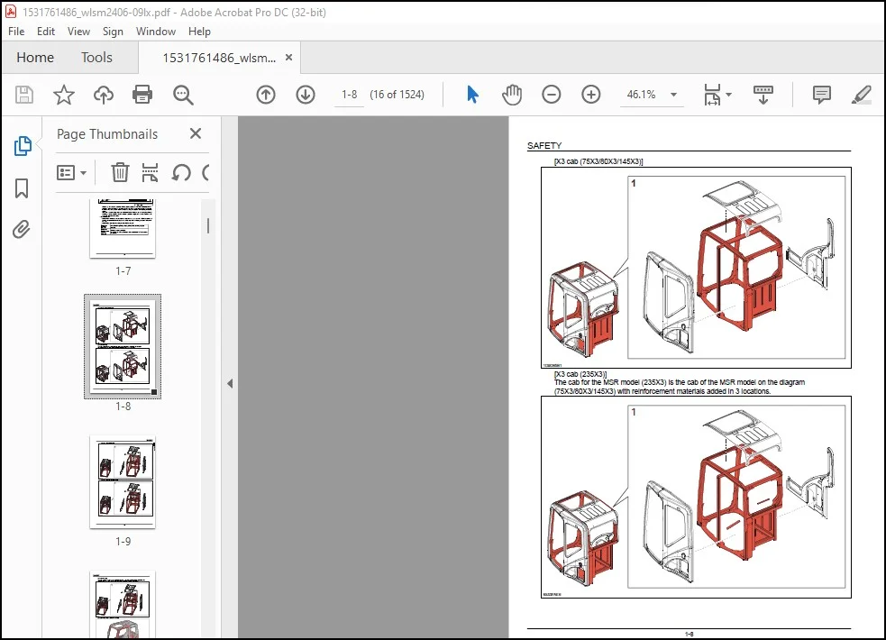
ROPS 14
ROPS Judgment Method 14
Standard Torque Data For Cap Screws And Nuts 19
Bolt and Nut Tightening 19
A LOWER 21
Specifications 25
250X3 25
Travel Lower Body 25
Main Equipment Table 26
250X3 26
Lower Component 26
Travel Unit 26
Take-up Roller 26
Upper Roller 26
Lower Roller 26
Recoil Spring 26
Shoe 27
Center Joint 27
Main Equipment Structure and Operation Explanation 28
Travel Motor 28
Travel motor operation explanation 28
Explanation of Component Device Operation 28
Double Counter Balance Valve 28
Crossover relief valve 33
Automatic 2-speed Switchover Mechanism 35
Parking Brake Function 39
Piston Motor 40
Reduction Gear 41
Port Diagram 43
Travel Motor 43
Center Joint 43
Basic Functions 44
Travel Speed Selection 44
Travel Alarm 45
Removal and Installation of Track 48
Removal and Installation of Shoe Assembly 48
Removal of Shoe Assembly 48
Installation of Shoe Assembly 49
Removal and Installation of Shoe Plate 51
Removal of Shoe Plate 51
Installation of Shoe Plate 51
Precautions for Shoe Bolt Installation 52
Removal and Installation of Roller 53
Removal and Installation of Upper Roller 53
Removal of Upper Roller 53
Installation of Upper Roller 54
Assembly and Disassembly of Upper Roller 55
Configuration Diagram 56
Dimension Diagram 56
Jig Dimension Diagram 57
Disassembly Procedures 57
Assembly Procedures 59
Removal and Installation of Lower Roller 62
Removal of Lower Roller 62
Installation of Lower Roller 63
Assembly and Disassembly of Lower Roller 64
Configuration Diagram 64
Dimension Diagram 65
Jig Dimension Diagram 65
Disassembly Procedures 66
Assembly Procedures 68
Removal and Installation of Drive Sprocket 71
Removal of Drive Sprocket 71
Installation of Drive Sprocket 72
Removal and Installation of Take-up Roller 73
Removal of Take-up Roller 73
Installation of Take-up Roller 74
Assembly and Disassembly of Take-up Roller 75
Configuration Diagram 76
Dimension Diagram 76
Jig Dimension Diagram 77
Disassembly Procedures 77
Assembly Procedures 80
Removal and Installation of Grease Cylinder 83
Removal of grease cylinder 83
Installation of grease cylinder 84
Assembly and Disassembly of Tension Shock Absorber 85
Configuration Diagram 85
Dimension Diagram 86
Jig Dimension Diagram 86
Disassembly procedures 86
Assembly procedures 87
Removal and Installation of Center Joint 89
Removal of Center Joint 89
Installation of Center Joint 91
Assembly and Disassembly of Center Joint 93
Configuration Diagram 94
Dimension Diagram 95
Jig Dimension Diagram 96
Disassembly Procedures 96
Assembly Procedures 97
Removal and Installation of Travel Motor 100
Removal of Travel Motor 100
Installation of Travel Motor 102
Assembly and Disassembly of Travel Motor 105
Tools for Assembly and Disassembly 105
Standard Tools 105
Secondary Materials 106
Special Tool (jig) 108
Measurement Device 108
Motor Disassembly Procedures 109
Precautions before Motor Disassembly 109
Tightening Torque 110
Disassembly Procedure 111
Maintenance Standards 120
Motor Parts Maintenance Standards 120
Reduction Gear Parts Maintenance Standards 122
Motor Assembly Procedures 124
Precautions before Motor Assembly 124
Assembly Procedure 125
Motor Installation 138
Inspection 138
Hydraulic Oil and Gear Oil Filling 140
Initial Pre-conditioning Operation 141
Troubleshooting 142
Structural Diagram 150
Internal Structure Diagram 153
Part Table 155
Maintenance Standards 156
Drive sprocket 156
Take-up roller 157
Upper roller 158
Lower Roller 159
Track Shoe (Grouser Shoe) 160
Inspection Gauge 161
For Drive Sprocket 161
For Take-up Roller 161
For Upper Roller 162
For Lower Roller 162
Pressure Measurement and Adjustment Procedures 163
Main Pressure Measurement 163
Travel pressure measurement 163
Drain Volume Measurement Procedures 164
Preparations 164
Travel Motor Drain Volume Measurement 164
Air Bleed Procedure 166
Travel Motor 166
B C SWING UNIT, COUNTERWEIGHT 167
Specifications 170
250X3 170
Upper Side Work System 170
Swing Units 170
Main Equipment Table 171
250X3 171
Upper Component 171
Swing Unit 171
Main Equipment Structure and Operation Explanation 172
Swing Motor 172
Swing Motor Operation Explanation 172
Hydraulic Motor Section 172
Valve Casing Section 172
Brake Section 173
Relief Valve Operation Explanation (relief valve model: KRD22EK10) 174
Swing Motor Internal Structure Diagram 176
Port Diagram 179
Swing motor 179
Basic Functions 180
Swing Brake 180
Swing Lock 181
Swing Speed Limit 182
Free Swing (option) 183
Removal and Installation of Swing Unit 184
Removal of Swing Unit 184
Installation of Swing Unit 186
Assembly and Disassembly of Swing Motor 187
Causes of Trouble and Solutions 188
Maintenance Standard Table 190
Required Tools 191
Jig 192
Disassembly 192
Assembly 194
Swing Motor Internal Structural Diagram 198
Assembly and Disassembly of Swing Unit 200
Disassembly 200
Assembly 201
Assembly and Disassembly of Swing Reduction Gear 203
Disassembly 203
Assembly 206
Swing Reduction Gear Breakdown Diagram 209
Swing Reduction Gear Structure Diagram 210
Removal and Installation of Counterweight 211
Removal of Counterweight 211
Installation of Counterweight 212
Pressure Measurement and Adjustment Procedures 214
Main Pressure Measurement 214
Swing pressure measurement 214
Drain Volume Measurement Procedures 215
Preparations 215
Swing Motor Drain Volume Measurement 215
Air Bleed Procedure 216
Swing Motor 216
H ENGINE 217
Specifications 222
250X3 222
Engine 222
Cooling System 222
Capacities, Filters 222
Coolant and Oil Capacities 222
Fuel Filter 222
Main Equipment Table 223
250X3 223
Engine-related 223
Engine 223
DPD 223
Air Cleaner (double element) 223
Radiator 223
Basic Functions 224
Fuel Gauge 224
Coolant Temperature Gauge 226
DPD Gauge 228
Fuel Economy Gauge 229
Neutral Start 230
Engine Start/Stop Control 231
Power-cut Delay 232
Preheating 233
Throttle 234
Engine Throttle Switch Position Detection 235
Idling Start 241
Auto Idle 242
One-touch Idle 242
Auto Warm Up 244
Quick Warm Up 244
Idling Stop 246
Idle up 248
Work Mode Control 249
Engine Emergency Stop 251
Coolant Level Reduction 251
Engine Air Filter Clog 251
Fuel Filter Clog 252
DPD Regeneration 254
Automatic Regeneration 255
Manual Regeneration 257
Optional Manual Regeneration 259
Hydraulic Assisting Load 261
Main Data 262
Function, structure, and operations 264
Symptom 321
Frequent Manual DPD Regeneration 321
DPD Regeneration Taking Excessively Long 322
Engine Start Problems 323
Engine Stalling 325
Engine Hunting, Rough Idling 327
Excess Amount of White Smoke in Exhaust Gas 329
Excess Amount of Black Smoke in Exhaust Gas 329
Abnormal Noise 330
High Fuel Consumption 331
High Oil Consumption 332
Engine Output Deficiency 333
Functional Inspection 335
Inspection of Scan Tool Power Supply System 335
Start Circuit System Inspection 335
Engine Compression Pressure Inspection 336
Start System Inspection 337
Fuel System Inspection 337
Suction air system inspection 338
Exhaust system inspection 338
Inspection of EGR Control System 338
Glow Control System Inspection 339
DPD Function Inspection 340
OBD System Check 342
Inspection of the monitor warning light illumination circuit system 343
Inspection of the monitor warning light blinking circuit system 343
Maintenance precautions 345
Removal and Installation of Engine Assembly 348
Removal of Engine Assembly 348
Installation of Engine Assembly 353
Removal and Installation of Fuel Cooler, Engine Intercooler, Radiator, and Oil Cooler 354
Removal and Installation of Fuel Cooler 354
Removal of Fuel Cooler 354
Installation of Fuel Cooler 355
Removal and Installation of Engine Intercooler 355
Removal of Intercooler 355
Installation of Inter Cooler 355
Removal and Installation of Radiator 356
Removal of Radiator 356
Installation of Radiator 359
Removal and Installation of Oil Cooler 359
Removal of Oil Cooler 360
Installation of Oil Cooler 363
Removal and Installation of Turbo Charger 366
Turbocharger assembly Removal 366
Turbocharger assembly Installation 367
Removal and Installation of EGR Valve 370
EGR valve Removal 370
EGR valve Installation 371
Removal and Installation of Engine Hood 374
Removal of Engine Hood 374
Installation of Engine Hood 375
Removal and Installation of Muffler 376
Removal of Muffler 376
Installation of Muffler 376
Removal and Installation of Cylinder Head Cover 378
Cylinder head cover Removal 378
Installation of Cylinder Head Cover 378
Removal and Installation of Cylinder Head 379
Removal of Cylinder Head 379
Disassembly of Cylinder Head 387
Assembly of Cylinder Head 392
Installation of Cylinder Head 399
Inspection 414
Removal and Installation of Cylinder Block 420
Removal of Cylinder Block 420
Installation of Cylinder Block 435
Inspection 468
Lubrication System 470
Removal and Installation of Oil Pan 470
Removal of Oil Pan 470
Installation of Oil Pan 470
Removal and Installation of Oil Level Switch 470
Removal of Oil Level Switch 470
Installation of Oil Level Switch 471
Removal and Installation of Oil Pump Assembly 471
Removal of Oil Pump Assembly 471
Disassembly of Oil Pump Assembly 483
Assembly of Oil Pump Assembly 483
Installation of Oil Pump Assembly 483
Inspection 506
Engine oil Inspection 507
Removal and Installation of Oil Port Cover 507
Removal of Oil Port Cover 507
Installation of Oil Port Cover 507
Cooling System 509
Removal and Installation of Water Pump Assembly 509
Removal of Water Pump Assembly 509
Installation of Water Pump Assembly 510
Inspection of Water Pump Assembly 511
Removal and Installation of Thermostat 512
Removal of Thermostat 512
Installation of Thermostat 512
Inspection 513
Inspection of Coolant 513
Inspection of Cooling Fan Belt 515
Removal and Installation of Overheat Switch 515
Removal of Overheat Switch 515
Installation of Overheat Switch 515
Removal and Installation of Exhaust Manifold 516
Removal of Exhaust Manifold 516
Installation of Exhaust Manifold 518
Inspection 522
Disassembly, Removal and Installation of DPD Assembly 523
Disassembly of DPD Assembly 523
Assembly of DPD Assembly 524
Inspection 527
Removal and Installation of Fuel Tank 528
Removal of Fuel Tank 528
Installation of Fuel Tank 531
Removal and Installation of Fuel Supply Pump 532
Removal of Fuel Supply Pump 532
Installation of Fuel Supply Pump 533
Removal and Installation of Common Rail Assembly 536
Removal of Common Rail Assembly 536
Installation of Common Rail Assembly 538
Removal and Installation of Injector 543
Removal of injector 543
Installation of Injector 547
Removal and Installation of Starter Motor 552
Removal of Starter Motor 552
Installation of Starter Motor 553
Removal and Installation of Alternator 554
Removal of Alternator 554
Installation of Alternator 555
Preheating System 556
Removal and Installation of Glow Plug 556
Removal of Glow Plug 556
Installation of Glow Plug 556
Glow plug Inspection 556
Introduction to the trouble diagnosis 557
Removal and Installation of Suction Control Valve 565
Removal of Suction Control Valve 565
Installation of Suction Control Valve 566
Removal and Installation of Fuel filter pressure 567
Fuel filter pressure sensor Removal 567
Fuel filter pressure sensor Installation 568
Removal and Installation of Engine coolant temperature sensor 568
Engine coolant temperature sensor Removal 568
Engine coolant temperature sensor Installation 568
Engine coolant temperature sensor Inspection 568
Removal and Installation of CKP sensor 569
CKP sensor Removal 569
CKP sensor Installation 569
CKP sensor Inspection 569
Removal and Installation of CMP sensor 569
CMP sensor Removal 569
CMP sensor Installation 570
CMP sensor Inspection 570
Removal and Installation of Oil pressure sensor 570
Oil pressure sensor Removal 570
Oil pressure sensor Installation 570
Oil pressure sensor Inspection 570
Removal and Installation of Boost sensor 571
Boost sensor Removal 571
Boost sensor Installation 571
Removal and Installation of Boost temperature sensor 572
Boost temperature sensor Removal 572
Boost temperature sensor Installation 572
Removal and Installation of IMT sensor 572
IMT sensor Removal 572
IMT sensor Installation 572
Removal and Installation of Exhaust differential pressure sensor 573
Exhaust differential pressure sensor Removal 573
Exhaust differential pressure sensor Installation 573
Exhaust differential pressure sensor Inspection 574
Removal and Installation of Exhaust gas temperature sensor 574
Removal of Exhaust Gas Temperature Sensor 574
DPD temperature sensor Installation 575
Exhaust gas temperature sensor Inspection 576
Engine-side Diagnostic Trouble Code List 577
Troubleshooting – engine 579
Engine-side Trouble 579
Diagnostic Trouble Code 0016 Abnormally Correlation Between Crankshaft Position and Camshaft Position 579
Diagnostic trouble code 0045 – Turbocharger Boost Pressure Control System Abnormality 580
Diagnostic Trouble Code 0087 Fuel Rail System Pressure Low Pressure Error 582
Diagnostic Trouble Code 0088 Fuel Rail System Pressure High Pressure Error 585
Diagnostic Trouble Code 0091 Fuel Rail Pressure Regulator Control System Low Input 588
Diagnostic Trouble Code 0092 Fuel Rail Pressure Regulator Control System High Input 589
Diagnostic Trouble Code 0093 Fuel System Leak Detection 591
Diagnostic Trouble Code 0102 Mass Air Flow Sensor System Low Input 594
Diagnostic Trouble Code 0103 Mass Air Flow Sensor System High Input 595
Diagnostic Trouble Code 0112 Intake Temperature Sensor System Low Input 596
Diagnostic Trouble Code 0113 Intake Temperature Sensor System High Input 596
Diagnostic Trouble Code 0117 Engine Coolant Temperature Sensor System Low Input 597
Diagnostic Trouble Code 0118 Engine Coolant Temperature Sensor System High Input 598
Diagnostic Trouble Code 0122 Throttle Sensor System Low Input 599
Diagnostic Trouble Code 0123 Throttle Sensor System High Input 600
Diagnostic Trouble Code 0182 Fuel Temperature Sensor System Low Input 601
Diagnostic Trouble Code 0183 Fuel Temperature Sensor System High Input 602
Diagnostic Trouble Code 0192 Fuel Rail Pressure Sensor System Low Input 603
Diagnostic Trouble Code 0193 Fuel Rail Pressure Sensor System High Input 604
Diagnostic Trouble Code 0201 Injector First Cylinder System Error 605
Diagnostic Trouble Code 0202 Injector Second Cylinder System Error 606
Diagnostic Trouble Code 0203 Injector Third Cylinder System Error 608
Diagnostic Trouble Code 0204 Injector Fourth Cylinder System Error 609
Diagnostic Trouble Code 0217 Engine Coolant High Temperature Error 611
Diagnostic Trouble Code 0219 Engine High Rpm Error 612
Diagnostic Trouble Code 0234 Turbocharger High Boost Pressure Abnormality 613
Diagnostic Trouble Code 0237 Boost Sensor Circuit Low Input 614
Diagnostic Trouble Code 0238 Boost Sensor Circuit High Input 615
Diagnostic Trouble Code 0299 Turbocharger Low Boost Pressure Abnormality 616
Diagnostic Trouble Code 0335 Crankshaft Position Sensor System Error 618
Diagnostic Trouble Code 0340 Camshaft Position Sensor System Error 619
Diagnostic Trouble Code 0380 Glow Plug System Error 621
Diagnostic Trouble Code 0404 EGR1 Control System Error 622
Diagnostic Trouble Code 0409 EGR1 Position Sensor System Error 623
Diagnostic Trouble Code 0411 Turbocharger Control Module Signal Error 624
Diagnostic Trouble Code 041C IMT Sensor System High Input 625
Diagnostic Trouble Code 041D IMT Sensor System Low Input 626
Diagnostic Trouble Code 0426 Pre-filtered Exhaust Gas High Temperature Error 627
Diagnostic Trouble Code 0427 Exhaust Temperature Sensor 1 System Low Input (pre-filter) 627
Diagnostic Trouble Code 0428 Exhaust Temperature Sensor 1 System High Input (pre-filter) 628
Diagnostic Trouble Code 042B Exhaust Gas High Temperature Error Before Oxidation Catalyst 630
Diagnostic Trouble Code 042C Exhaust Temperature Sensor 2 System Low Input (before oxidation catalyst) 630
Diagnostic Trouble Code 042D Exhaust Temperature Sensor 2 System High Input (before oxidation catalyst) 631
Diagnostic Trouble Code 0522 Oil Pressure Sensor System Low Input 633
Diagnostic Trouble Code 0523 Oil Pressure Sensor System High Input 634
Diagnostic Trouble Code 0560 System Voltage Abnormality (12 V system) 635
Diagnostic Trouble Code 0563 System Voltage High Input 636
Diagnostic Trouble Code 0601 Control Module Memory Checksum Error 637
Diagnostic Trouble Code 0602 Control Module Program Error 637
Diagnostic Trouble Code 0604 Control Module RAM Error 638
Diagnostic Trouble Code 0606 Control Module Processing Device Error 638
Diagnostic Trouble Code 060B Control Module A/D Converter Processing System Characteristics Error 639
Diagnostic Trouble Code 0638 Throttle Actuator Control System Characteristic Error 639
Diagnostic Trouble Code 0641 Sensor Voltage System Error (reference 1) 641
Diagnostic Trouble Code 0651 Sensor Voltage System Error (reference 2) 642
Diagnostic Trouble Code 0685 ECM Main Relay Control System Low Input 643
Diagnostic Trouble Code 0687 ECM Main Relay Control System High Input 644
Diagnostic Trouble Code 0697 Sensor Voltage System Error (reference 3) 645
Diagnostic Trouble Code 1093 Fuel Rail Pressure Low Pressure Error 646
Diagnostic Trouble Code 1112 Boost Temperature Sensor System Low Input 649
Diagnostic Trouble Code 1113 Boost Temperature Sensor System High Input 650
Diagnostic Trouble Code 1261 Injector Group 1 Voltage Control System Error 651
Diagnostic Trouble Code 1262 Injector Group 2 Voltage Control System Error 651
Diagnostic Trouble Code 1293 Fuel Filter Pressure Sensor System Low Input 652
Diagnostic Trouble Code 1294 Fuel Filter Pressure Sensor System High Input 653
Diagnostic Trouble Code 1404 EGR 1 Close Position Characteristic Error 654
Diagnostic Trouble Code 1455 PM Over Caught 2 655
Diagnostic Trouble Code 1471 DPD Regeneration Error 657
Diagnostic Trouble Code 1621 Control Module EEPROM Error 659
Diagnostic Trouble Code 1655 Sensor Voltage System Error (reference 4) 660
Diagnostic Trouble Code 2146 Injector Group 1 Voltage Control System Error 661
Diagnostic Trouble Code 2149 Injector Group 2 Voltage Control System Error 663
Diagnostic Trouble Code 2228 Atmospheric Pressure Sensor System Low Input 664
Diagnostic Trouble Code 2229 Atmospheric Pressure Sensor System High Input 665
Diagnostic Trouble Code 242F PM Over Collection 666
Diagnostic Trouble Code 2452 DPD Differential Pressure Sensor System Error 669
Diagnostic Trouble Code 2453 DPD Differential Pressure Sensor System Characteristic Error 670
Diagnostic Trouble Code 2454 DPD Differential Pressure Sensor System Low Input 672
Diagnostic Trouble Code 2455 DPD Differential Pressure Sensor System High Input 673
Diagnostic Trouble Code 2456 DPD Differential Pressure Sensor Learning Position Error 674
Diagnostic Trouble Code 2458 DPD Regeneration Time Abnormality 675
Diagnostic Trouble Code 0001 CAN Bus Error 676
Diagnostic Trouble Code 0073 CAN Bus Error 677
Diagnostic Trouble Code 0101 TCM Communication Error 678
Diagnostic Trouble Code 0110 Turbocharger Control Module Communication Abnormality 679
Data Reference Values 681
Idle Speed 681
Dual Pump Relief 682
J HYDRAULIC EQUIPMENT (PUMP, OPERATION SYSTEM VALVE) 685
Specifications 690
250X3 690
Operating Device 690
Hydraulic Equipment 691
Hydraulic Device 691
Control Valve and Cylinder 691
Capacities, Filters 691
Hydraulic Filters 691
Main Equipment Table 692
250X3 692
Hydraulic Device 692
Hydraulic Pump 692
Control-related 692
Control Valve 692
Solenoid Valve (5 stack) 693
Valve for Left/Right Operations 693
Remote Control Valve for Travel Operations 693
Remote Control Valve Characteristic Diagram 694
Operation Remote Control Valve Control Diagram 694
Travel Remote Control Valve Control Diagram 695
Cushion Valve (heat circuit, with shuttle valve) 695
Selector Valve (option) 695
Basic Functions 696
Oil Temperature Gauge 696
Static Horsepower Control 697
Pressure Boost Control 698
Pump Standby Pressure Control 701
Swing Relief Cut 704
Boom Down Energy Save 705
Auto Energy Save 706
Stroke Control 707
Feed Pump Automatic Stop 709
Hydraulic Fluid Filter Clog 709
Solenoid Sticking Prevention 711
Hot Shutdown Warning 712
Breaker Mode 713
Crusher Mode 713
Port Diagram 714
Hydraulic Pump (standard model) 714
Control Valve 715
Relief Valve 715
5 Stack Solenoid Valve 718
2 Stack Solenoid Valve 719
Remote Control Valves (upper, travel) 720
Remote Control Valves (left-right) 720
Remote Control Valve (travel) 720
Reducing Valve (3 stack) 721
Cushion Valve 721
2-way Selector Valve 722
Direction Valve 722
Shut-off Valve 723
Relief Valve (electromagnetic proportional) 723
Manifold Under Cab 724
Manifold (accumulator section) 724
Manifold (hydraulic tank section) 725
Hydraulic Device 726
Pump P-Q Diagram 726
Main Equipment Structure and Operation Explanation 727
Hydraulic Pump 727
Structure and Operation Explanation 727
Hydraulic Pump Internal Structure Diagram 728
Overall View 728
Drive Shaft Front Side 729
Drive Shaft Rear Side 730
Part Table 731
Regulator 732
Regulator Operation Explanation 732
Regulator Operation Explanation Diagram 735
Front Side Regulator Internal Structure Diagrams 736
Rear Side Regulator Internal Structure Diagram 738
Gear Pump 740
Gear Pump Internal Structure Diagram 740
Structure and Operation Explanation 741
Control Valve 742
Basic configuration 742
Operation 742
5 Stack Solenoid Valve Operation Explanation 777
External Shape Diagram and Component Parts 777
Operation Explanation 778
Upper Pilot Valve (remote control valve) 779
Structure 779
Function 779
Operation 780
Structural Diagram 783
Travel Pilot Valve (remote control valve) 784
Operation 784
Pressure Reduction Valve Section 785
Operating Section Damping Mechanism Section 785
Structural Diagram 788
Cushion Valve 789
Structure 789
Operation Explanation 790
Pressure Bleeding Operations 794
Removal and Installation of Hydraulic Tank 795
Removal of Hydraulic Tank 795
Installation of Hydraulic Oil Tank 799
Removal and Installation of Hydraulic Pump 800
250X3 800
Removal of Hydraulic Pump 800
Installation of Hydraulic Pump 803
Removal and Installation of Pump Coupling 806
Removal of Pump Coupling 806
Installation of Pump Coupling 807
Removal and Installation of Control Valve 809
Removal of Control Valve 809
Installation of Control Valve 811
Removal and Installation of Pilot Blocs 814
Removal and Installation of Travel Remote Control Valve 815
Removal of Travel Remote Control Valve 815
Installation of Travel Remote Control Valve 816
Removal and Installation of Operation Remote Control Valve 818
Removal of Operation Remote Control Valve (Left) 818
Installation of Operation Remote Control Valve (Left) 820
Removal of Operation Remote Control Valve (right side) 822
Installation of Operation Remote Control Valve (right side) 824
Removal and Installation of 5 Stack Solenoid 826
Removal of 5 Stack Solenoid Valve 826
Installation of 5 Stack Solenoid Valve 828
Removal and Installation of Cushion Valve 831
Removal of Cushion Valve 831
Installation of Cushion Valve 832
Procedures for Assembly and Disassembly of Hydraulic Pump Main Unit 835
Tools 835
Disassembly procedures 835
Assembly procedures 837
Pump Main Unit Maintenance Standards 840
Replacement standards for worn parts 840
Standards for repairing cylinders, valve plates, and swash plates (shoe plates) 840
Tightening torque 841
Overall View 842
Attached diagram 1 pump assembly cross-section diagram 842
Drive Shaft Front Side 843
Drive Shaft Rear Side 844
Part Table 845
Operation explanation 846
Regulator adjustment 849
Tables and diagrams 851
Regulator Assembly and Disassembly Procedures 855
Tools 855
Disassembly preparations 855
Disassembly procedures 855
Assembly procedures 857
Diagram 1 Front-side regulator assembly cross-section diagram (KR3K-9Y04-HV) 860
Diagram 2 Rear-side regulator assembly cross-section diagram (KR3K-9Y04-HV) 863
Procedures for Assembly and Disassembly of Control Valve 866
Disassembly 866
Cautions for disassembly 866
Disassembly procedure 866
Removal of long cap and pull out of main spool 866
Disassembly of arm 1 parallel-tandem spool, neutral cut spool section 867
Disassembly of arm regeneration release valve section 867
Disassembly of load check valve section 868
Disassembly of antidrift valve section 868
Disassembly of relief valve 869
Disassembly of option section 869
Disassembly of straight travel signal control valve 869
Disassembly of other plugs 869
Disassembly of add-on section 869
Disassembly of valve housing union bolt 870
Cleaning 870
Inspection 870
Cautions for Assembly 870
Cautions for O-Ring handling 870
Cautions for spool handling 870
Adhesive Application Method (for male thread section and female thread section of parts requiring adhesion) 870
Procedure for assembly of sub-assembly 871
Assembly of spool assembly (main spool) 871
Assembly of arm 1 parallel-tandem spool assembly 871
Assembly of neutral cut spool assembly 871
Assembly of antidrift valve assembly 872
Procedure for assembly of control valve main unit 872
Assembly of relief valve 872
Assembly of load check valve 872
Assembly of antidrift valve 873
Assembly of option section 873
Assembly of arm regeneration release valve 873
Assembly of arm 1 parallel-tandem spool 873
Assembly of neutral cut spool 873
Assembly of main spool 873
Assembly of straight travel signal control valve 874
Assembly of add-on section 874
Assembly of other plugs 874
Internal Structure Diagram 875
Parts List 882
Relief valve 883
Procedures for assembly and disassembly of main relief valve 883
Procedures for assembly and disassembly of overload relief valve 884
Procedures for assembly and disassembly of low-pressure relief valve 884
Procedures for assembly and disassembly of add-on main relief valve 885
Relief valve adjustment 886
Installation 886
Run 886
Troubles and Countermeasures 886
Procedures for Assembly and Disassembly of Operation Remote Control Valve 888
Maintenance Procedures 888
Required Tools and Tightening Torque 888
Maintenance Standards 889
Disassembly Procedures 890
Assembly Procedures 892
Causes of Trouble and Countermeasures 895
Procedures for Assembly and Disassembly of Travel Remote Control Valve 899
Maintenance Procedures 900
Disassembly Procedures 900
Assembly Procedures 904
Causes of Trouble and Countermeasures and Cross-section Diagram 909
Assembly and Disassembly of Cushion Valve 912
Disassembly Procedures 912
Reverse Operation Spool Section 912
Check Plunger Section with Throttle 912
Shuttle Valve Section 912
Assembly Procedures 913
Reverse Operation Spool Section 913
Check Plunger Section with Throttle 913
Shuttle Valve Section 913
Written Materials 914
Pressure Measurement and Adjustment Procedures 916
Procedures for Pressure Measurement from the Monitor Display 916
Monitor and Switch Panel 916
Pressure Measurement Method 916
Operating Method 916
PROCEDURES FOR MEASURING HYDRAULIC OIL TEMPERATURE FROM THE MONITOR DISPLAY 917
Hydraulic Oil Temperature Measurement Method 917
Operating Method 917
Procedures for Pressure Measurement by Installing Pressure Gauge 918
Preparations 918
Items to prepare 918
Pressure Measuring Port 919
Control Valve 921
Location of Relief Valves 921
Pressure Measurement Preparations 923
Pressure Measurement 924
Main Pressure Measurement 924
A Attachment Pressure Measurement 926
Boom-down pressure measurement 927
Option line pressure measurement 927
Pilot Pressure Measurement 927
Installation of Pressure Gauge 927
Negative Control Pressure Measurement 928
Pressure gauge installation 928
Pressure Adjustment 928
Main Pressure Adjustment 928
Pressure measurement and adjustment preparation work 929
Main relief pressure adjustment 930
Overload relief pressure adjustment 931
Swing Relief Pressure Adjustment 932
Pilot Pressure Adjustment 933
Hydraulic Pump Flow Measurement Procedures 934
Preparations 934
Items to Prepare 934
Work Preparations 935
Flow Measurement 936
Air Bleed Procedure 938
Hydraulic Pump 938
Check 938
Hydraulic Equipment Layout 939
Overall view 940
Pump Chamber Hydraulic Equipment Layout 941
Swing Body Center Section Hydraulic Equipment Layout 943
HOUSING LEFT SIDE HYDRAULIC EQUIPMENT LAYOUT 944
LAYOUT OF HYDRAULIC EQUIPMENT IN CAB 945
J EXPLANATION OF HYDRAULIC CIRCUIT AND OPERATIONS (STANDARD) 947
J EXPLANATION OF HYDRAULIC CIRCTUIT AND OPERATIONS (OPTION) 1011
N CAB 1025
Removal and Installation of Operator’s Seat 1028
Removal of Operator’s Seat 1028
Installation of Operator’s Seat 1028
Removal and Installation of Cab Assembly 1029
Removal of Cab Assembly 1029
Installation of Cab Assembly 1033
Removal and Installation of Wiper 1034
Removal of Wiper 1034
Installation of wiper 1034
Removal and Installation of Cab Front Glass 1035
Removal of Cab Front Glass 1035
Installation of Cab Front Glass 1036
Removal and Installation of Right-side Window Glass 1037
Removal of Right-side Window Glass 1038
Installation of Right-side Window Glass 1039
Removal and Installation of Door (Upper) Sash Glass 1042
Removal of Door (Upper) Sash Glass 1043
Installation of Door (Upper) Sash Glass 1044
Window Lock Adjustment Procedures 1047
Window Lock (front side) 1047
Window Lock (rear side) 1047
Tightening torque 1049
R ELECTRICAL PARTS 1051
Electrical and Engine Functions and Service Support 1056
Basic Functions 1057
Monitor Display Dimming 1057
Eco Gauge 1058
Diagnostic Trouble Code Indicator 1059
Clock 1059
Accessories 1060
Working Light 1060
Room lamp 1061
Radio Mute 1063
Wiper and Washer 1064
Horn 1065
Back/Side View Monitor 1066
Precautions When Installing the Camera 1066
Anti-theft 1067
Enabling the anti-theft function 1067
Password 1067
Immobilizer Key 1068
Battery Disconnect Switch 1069
Reset 1070
Half Reset/All Reset 1070
Milli-amp List 1071
Safety 1073
Lever Lock 1073
Alternator Power Generation Detection 1074
Service Support 1076
Screen Operations 1076
Screen Display List 1076
CHECK Screen List 1077
MACHINE STATUS 1077
FAULT HISTORY 1081
WORK HISTORY 1082
ENGINE HISTORY 1084
HYDRAULIC HISTORY 1088
PART NUMBER 1090
List of Control Unit Screens 1091
CONTROLLER A 1092
CONTROLLER B 1095
MONITOR 1097
ECM 1099
AIR CONDITIONER 1099
COMMUNICATION 1100
SETUP Screen List 1101
MACHINE SELECT 1101
PARAMETERS 1105
RESET Screen List 1107
Setting 1108
Model Selection 1108
Throttle Volume Default Setting Value 1113
Password Setting 1113
Clock Adjustment 1114
Parameter Setting 1114
Option Flow Pressure Setting 1117
Screen Brightness Setting 1120
Service Monitor 1121
How to get into “Service Screen” 1121
General Operation on Service Monitor 1121
Engine Service Monitor 1122
Service Monitor Structure 1122
ENGINE INFORMATION 1123
Data Confirmation 1123
Data Transfer (Copy) 1123
QR (INJECTOR) CODE 1125
Injector Number 1125
Screen Layout 1125
Data Source Selection 1126
Manual Input 1126
DEVICE TEST 1127
Common Rail Pressure Test 1127
Injector Balance Test 1128
Injector Forced Drive Test 1129
ECM Memory Clear 1129
DPD Slow Regeneration 1130
DPD Manual Regeneration 1131
DPD Automatic Regeneration 1132
EGR Valve Control Test (if equipped) 1133
VG Turbo Control Test 1134
Intake Throttle Control Test 1135
Turbo Boost Test 1136
Computer Explanation 1137
Connection Connector Pin Layout 1143
Computer A 1143
Computer B 1144
Monitor 1145
Sequence Circuit Diagram 1146
Code table 1146
Overall 1148
Block diagram 1150
Computer A 1150
Computer B 1151
ECM 1152
Monitor 1153
Air Conditioner 1154
Lever Lock 1155
Horn 1155
Working lights 1155
Option 1156
Other 1157
Electrical Symbol List 1158
Electrical Equipment Layout Diagram 1159
Main Unit Left Side Layout Diagram (radiator chamber) 1159
Engine Section Layout Diagram 1161
Main Unit Right Side Layout Diagram (pump chamber) 1164
Main Unit Center Section Layout Diagram 1165
Cab Layout Diagram 1 1166
Cab Layout Diagram 2 1168
Layout Around Operator Seat 1170
Stand Alone Parts Diagram 1171
Removal and Installation of Wiper Controller 1190
Removal of Wiper Controller 1190
Installation of wiper controller 1190
Removal and Installation of Wiper Motor 1191
Removal of Wiper Motor 1191
Installation of wiper motor 1192
Removal and Installation of Monitor 1193
Removal of Monitor 1193
Installation of Monitor 1194
ECM Replacement Procedure 1195
Removal and Installation of ECM 1196
Removal of ECM 1196
Installation of ECM 1196
Removal and Installation of Computer A 1197
Removal of Computer A 1197
Installation of Computer A 1197
Removal and Installation of Computer B 1198
Removal of Computer B 1198
Installation of Computer B 1198
Air Conditioner Overall Diagram 1199
Frame 1199
Cab 1201
Equipment Layout Diagram 1204
Circuit Diagram 1206
Air Conditioner Circuit Diagram 1206
Explanation of Functions 1208
Explanation of Control 1208
Air Mix Motor Actuator Control 1209
Blow Mode Motor Actuator Control 1209
Refresh/Recirculate Switch Motor Actuator Control 1210
Blower Amp Control 1211
Compressor Clutch Control 1213
COOLMAX Control and HOTMAX Control 1214
Abnormality Detection and Control after Abnormality Detected 1214
Monitor Mode 1218
Door Switch Control 1219
Inside Air Filter Clogging Detection Control 1220
Actuator Inspection 1223
Air Mix Motor Actuator Inspection 1223
Refresh/Recirculate Switch Motor Actuator Inspection 1224
Mode Motor Actuator Inspection 1225
Self-diagnosis Function with Panel Display 1226
Abnormality Display and Self-check Procedures 1226
Abnormality Display Position 1226
Explanation of Abnormality Display 1226
Motor Actuator Abnormality 1226
Sensor Abnormality 1227
Explanation of Monitor Mode 1227
Monitor Mode Display Position 1227
Monitor Mode Display Operating Method 1228
Display Contents in Monitor Mode 1229
Air Conditioner Troubleshooting 1230
Part Function and Good/Poor Judgment 1235
Control Panel 1235
Blower Amp 1235
Relay 1236
Air Mix Actuator 1237
Refresh/Recirculate Actuator 1238
Blow Mode Actuator 1238
Evaporator Sensor 1239
Dual Pressure Switch 1239
Solar Radiation Sensor 1240
Inside Air Sensor 1241
Assembly and Disassembly of Unit 1242
Removal of Blower Unit 1242
Replacement of Blower Motor 1242
Replacement of Blower Amp 1242
Removal of Heater Core 1243
Removal of Heat Case Right/Left 1243
Replacement of Evaporator and Expansion Valve 1243
Installation of Evaporator Sensor 1244
Replacement of Motor Actuator 1244
Removal and Installation of Compressor 1245
Removal of Compressor 1245
Installation of Compressor 1245
Removal and Installation of Condenser 1246
Removal of Condenser 1246
Installation of Condenser 1247
Removal and Installation of Receiver Dryer 1248
Removal of Receiver Dryer 1248
Installation of Receiver Dryer 1249
Work Precautions 1250
Work Procedures 1251
Air Conditioner Refrigerant Filling is Divided into the “Vacuum Operation” and “Gas Filling Operation” 1251
Operation Chart 1251
Tools 1252
Filling Procedures 1253
Charging Hose Connection Positions 1253
Gauge Manifold Connection 1253
Vacuuming 1254
Gas Filling Operation, High-pressure Side 1255
Gas Filling Operation, Low-pressure Side 1256
R ELECTRICAL CONNECTOR WIRING DIAGRAM 1259
R ELECTRICAL PARTS AND WIRING ASSEMBLY DIAGRAM 1269
V ATTACHMENTS 1281
Main Equipment Table 1284
250X3 1284
Backhoe Attachment 1284
Cylinder 1284
Maintenance Standards 1285
Attachment (backhoe) 1285
1 Boom and Swing Frame Installation Section 1286
2 Boom Cylinder and Swing Frame Installation Section 1287
3 Boom and Boom Cylinder Installation Section 1288
4 Boom and Arm Cylinder Installation Section 1289
5 Boom and Arm Installation Section 1290
6 Arm and Arm Cylinder Installation Section 1291
7 Arm and Bucket Cylinder Installation Section 1292
8 Arm and Arm Link Installation Section 1293
9 Bucket and Bucket Link Installation Section 1294
10 Bucket Link and Bucket Cylinder Installation Section 1295
11 Bucket and Arm Installation Section 1296
Removal and Installation of Bucket Cylinder 1297
Removal of Bucket Cylinder 1297
Installation of Bucket Cylinder 1299
Removal and Installation of Arm Cylinder 1300
Removal of Arm Cylinder 1300
Installation of Arm Cylinder 1302
Removal and Installation of Boom Cylinder 1304
Removal of Boom Cylinder 1304
Installation of Boom Cylinder 1306
Procedures for Operation/Assembly and Disassembly of Hydraulic Cylinder (made by KYB) 1309
Specifications and Structure Diagram (including the assembly diagram and parts table) 1309
Basic functions 1309
Function of Each Location 1309
Cylinder Head Assembly 1309
Piston Assembly 1310
Pipe Assembly 1312
Handling Precautions 1313
Precautions for Installing the Cylinder on the Machine Body 1313
Usage Cautions 1313
Maintenance and Inspection Cautions 1314
Maintenance Inspection and Service 1315
Trouble Diagnostics 1316
Storage Standards 1320
Storing Parts Individually (In principle, store indoors ) 1320
When Mounted on Vehicle Body 1321
Recommended Anti-rust Oil 1321
Assembly and Disassembly Procedures 1321
Preparations ····· Prepare the Following before Starting Disassembly 1321
General Work Precautions 1321
Maintenance Standards 1321
Inspection after Assembly 1322
Required Tool 1323
General Tool 1323
Special Jig 1325
Special Jigs Part Number List 1326
Disassembly Procedures 1327
Drain the Oil 1327
Secure the Cylinder 1327
Removal of Cylinder Head 1327
Pull out the Piston Rod 1327
Fasten the Piston Rod 1328
Remove the Piston Nut 1328
Removal of Piston etc 1328
Disassembly of the Retraction Side Cushion Ring 1329
Remove the Piston Seal 1329
Disassembly of the Buffer Ring 1329
Disassembly of U-ring and Wiper Ring 1329
Removal of O-ring and Backup Ring 1329
Disassembly of Bushing 1329
Removal of Pin Bushing 1330
Cleaning and Storage 1330
Assembly Procedures 1331
Installation of Pin Bushing 1331
Replacement of Seals 1331
Assembly of Cylinder Head Assembly 1331
Assembly of Piston Assembly 1332
Assembly of Piston Rod Assembly 1332
Insertion of Piston Rod into the Tube 1334
Cylinder Head Tightening 1334
Installation of Line 1334
Test Operation 1335
Usage Limits 1336
Structural Diagram 1338
Boom Cylinder 1338
Arm Cylinder 1340
Bucket Cylinder 1342
Port Diagram 1344
HBCV 1344
Removal and Installation of HBCV 1345
Removal and Installation of Arm HBCV 1345
Removal of Arm HBCV 1345
Installation of arm HBCV 1345
Removal and Installation of Boom HBCV 1346
Removal of Boom HBCV 1346
Installation of boom HBCV 1347
Air Bleed Procedure 1348
HBCV 1348
Boom Cylinder HBCV 1348
Arm Cylinder HBCV 1349
Removal and Installation of Bucket 1350
Removal of Bucket 1350
Installation of Bucket 1350
Removal and Installation of Bucket Link 1352
Removal of Bucket Link 1352
Installation of Bucket Link 1352
Removal and Installation of Arm 1354
Removal of Arm 1354
Installation of Arm 1355
Removal and Installation of Boom 1356
Removal of Boom 1356
Installation of Boom 1358
Z OTHER 1363
Specifications 1367
250X3 1367
ENGINE 1367
HYDRAULIC SYSTEM 1367
HYDRAULIC CONTROLS 1368
ELECTRICAL SYSTEM 1368
OPERATOR ENVIRONMENT 1369
UNDERCARRIAGE 1369
MASS 1370
DIGGING FORCE (with 1 1 m3 Sumitomo Bucket) (ISO 6015) 1370
DIMENSIONS 1370
WORKING RANGES 1371
SYSTEM FLUID CAPACITIES AND SPECIFICATIONS 1371
Arm Dimension 1372
250X3 1372
Standard Arm [3 00 m (9 8425 ft )] 1372
Short Arm [2 50 m (8 2021 ft )] 1374
Long Arm [3 52 m (11 5486 ft )] 1376
Main Unit Weight 1378
250X3 1378
Divided weight (standard specifications) 250X3 1378
Stand Alone Part Weight 1379
Shoe Weight (per side) 1379
Arm Weight 1379
Bolt Size and Torque Table 1380
Special Torque Settings 1380
Overall View 1384
250X3 1384
Standard Arm [3 00 m (9 8425 ft )] 1384
Short Arm [2 50 m (8 2021 ft )] 1385
Long Arm [3 52 m (11 5486 ft )] 1386
WORK RANGE DIAGRAM 1387
250X3 1388
Standard Arm [3 00 m (9 8425 ft )] 1388
Short Arm [2 50 m (8 2021 ft )] 1390
Long Arm [3 52 m (11 5486 ft )] 1392
New Machine Performance Judgment Table 1394
Table of Standards 1394
Measurement Method 1396
Engine Speed 1396
Pressure in Each Section 1396
Cylinder Falling Amount 1396
Attachment Speed 1396
Swing Speed 1397
Swing (180°) Brake Angle 1397
Travel Speed 1398
Travel Deviation 1398
Travel Sprocket Speed 1399
Shoe Tension Amount 1399
Swing Ball Race Bearing Movement Amount and Bucket Tip Movement Amount 1400
FLUIDS AND LUBRICANTS 1402
HYDRAULIC FLUID 1402
Engine Oil 1402
Oil Grade 1402
FUEL 1403
Conditions applicable to diesel fuel 1403
Recommended Conditions That Can Be Applied To Diesel Fuel 1403
Main Unit-side Diagnostic Trouble Code List 1404
Main Unit-side Trouble 1406
Diagnostic Trouble Code: 7000 P1 Pressure Sensor Signal Abnormality 1406
Diagnostic Trouble Code: 7001 P2 Pressure Sensor Signal Abnormality 1408
Diagnostic Trouble Code: 7002 N1 Pressure Sensor Signal Abnormality 1410
Diagnostic Trouble Code: 7003 N2 Pressure Sensor Signal Abnormality 1412
Diagnostic Trouble Code: 7020 Upper Pressure Sensor Signal Abnormality 1414
Diagnostic Trouble Code: 7021 Swing Pressure Sensor Signal Abnormality 1416
Diagnostic Trouble Code: 7022 Travel Pressure Sensor Signal Abnormality 1418
Diagnostic Trouble Code: 7023 Arm-in Pressure Sensor Signal Abnormality 1420
Diagnostic Trouble Code: 7040 Fuel Level Sensor Signal Abnormality 1422
Diagnostic Trouble Code: 7041 Oil Temperature Sensor Signal Abnormality 1424
Diagnostic Trouble Code: 7063 Return Filter Clog Switch Abnormality 1426
(Other than breaker specifications) 1426
Diagnostic Trouble Code: 7065 Boom-up Pilot Pressure Sensor Signal Abnormality 1427
Diagnostic Trouble Code: 7067 Bucket-close Pilot Pressure Sensor Signal Abnormality 1429
Diagnostic Trouble Code: 7200 Swing Brake Solenoid Signal Abnormality 1431
Diagnostic Trouble Code: 7201 Travel High-speed Solenoid Signal Abnormality 1433
Diagnostic Trouble Code: 7202 Pressure Boost Solenoid Signal Abnormality 1435
Diagnostic Trouble Code: 7203 Travel Alarm Buzzer Signal Abnormality 1438
Diagnostic Trouble Code: 7204 Power Save Solenoid Signal Abnormality 1440
Diagnostic Trouble Code: 7206 Option Line Switchover Solenoid Signal Abnormality 1443
Diagnostic Trouble Code: 7207 Free Swing Solenoid Signal Abnormality 1445
Diagnostic Trouble Code: 7212 Shut-off Solenoid Signal Abnormality 1447
Diagnostic Trouble Code: 7240 Pump Horsepower Proportional Valve Signal Abnormality 1449
Diagnostic Trouble Code: 7241 P1 Flow Control Proportional Valve Signal Abnormality 1451
Diagnostic Trouble Code: 7246 2 Pumps Flow Solenoid Signal Abnormality 1453
Diagnostic Trouble Code: 7247 Boom-down Proportional Valve Signal Abnormality 1455
Diagnostic Trouble Code: 7248 Arm-in Proportional Valve Signal Abnormality 1457
Diagnostic Trouble Code: 7250 Option Relief Pressure Proportional Valve Signal Abnormality 1459
Diagnostic Trouble Code: 7253 DPD Regeneration Request Output Signal Abnormality 1461
Diagnostic Trouble Code: 7254 Washer Output Abnormality 1463
Diagnostic Trouble Code: 7400 Abnormally High Coolant Temperature [(105°C (221 0°F) or higher)] 1465
Diagnostic Trouble Code: 7401 Abnormally High Coolant Temperature [ 110 °C ( 230 0 °F )or higher ] 1466
Diagnostic Trouble Code: 7404 Abnormally High Oil Temperature [98 °C (208 4 °F) or higher] 1467
Diagnostic Trouble Code: 7405 Abnormally High Boost Temperature [ 80 °C ( 176 0 °F )or higher ], 7406 Abnormally High Boost Temperature [ 90 °C ( 194 0 °F )or higher ] 1468
Diagnostic Trouble Code: 7420 Abnormally Low Alternator Voltage 1469
Diagnostic Trouble Code: 7421 Coolant Level Reduction 1471
Diagnostic Trouble Code: 7422 Abnormally Low Engine Oil Pressure 1472
Diagnostic Trouble Code: 7423 Air Cleaner Clogging 1473
Diagnostic Trouble Code: 7424 Return Filter Clogging (with breaker) 1474
Diagnostic Trouble Code: 7426 Fuel Filter Clogging 1 1475
Diagnostic Trouble Code: 7427 Fuel Filter Clogging 2 1476
Diagnostic Trouble Code: 7601 Monitor Communication Abnormality 1477
Diagnostic Trouble Code: 7602 ECM Communication Abnormality 1478
Diagnostic Trouble Code: 7605 ECM Mismatch 1479
Diagnostic Trouble Code: 7606 EEPROM Data Abnormality 1480
Diagnostic Trouble Code: 7607 Computer C Communication Abnormality 1481
Diagnostic Trouble Code: 7608 Camera Abnormality 1482
Diagnostic Trouble Code: 7609 EEPROM (B) Data Abnormality 1484
Diagnostic Trouble Code: 7610 EEPROM (C) Data Abnormality 1485
Diagnostic Trouble Code: 7611 Computer A Communication Abnormality 1486
Diagnostic Trouble Code: 7612 Air Conditioner Communication Abnormality 1487
Diagnostic Trouble Code: 7613 Monitor Communication CAN Abnormality 1488
Diagnostic Trouble Code: 7614 Air Conditioner Panel Mismatch 1489
List of special tools 1490
NUMERICAL VALUE CONVERSION TABLE 1490
Unit conversion rate 1490
Length 1491
Area 1494
Volume 1495
Weight 1497
Pressure 1499
Torque 1501
Temperature 1503
A 1505
Travel Motor Special Tool 1505
250X3 1505
Take-up Roller Special Tool 1508
250X3 1508
Upper Roller Special Tool 1509
250X3 1509
Lower Roller Special Tool 1510
250X3 1510
C 1511
Swing Motor Special Tool 1511
250X3 1511
H 1514
Engine Oil Filter Special Tool 1514
210X3/250X3/350X3 1514
Fuel Filter Special Tool 1514
210X3/250X3/350X3 1514
Injector Special Tool 1514
210X3/250X3/350X3 1514
Circuit Test Special Tool 1515
250X3/300X3/350X3/470X3 1515
Valve Guide Special Tool 1515
210X3/250X3/300X3/350X3 1515
Cylinder Head Special Tool 1515
210X3/250X3/350X3/470X3 1515
Head Bolt Special Tool 1518
210X3/250X3/350X3/470X3 1518
Crankshaft Special Tool 1518
250X3 1518
Valve Spring Special Tool 1520
210X3/250X3/350X3/470X3 1520
J 1521
Remote Control Valve Special Tool 1521
250X3 1521
R 1523
Gas Filling Special Tool 1523
210X3/250X3/350X3 1523
V 1523
Attachment Special Tool (for Cylinder Assembly) 1523
Special Jigs Part Number List 1523
PLEASE NOTE:
- This is the same manual used by the dealers to diagnose and troubleshoot your vehicle
- You will be directed to the download page as soon as the purchase is completed. The whole payment and downloading process will take anywhere between 2-5 minutes
- Need any other service / repair / parts manual, please feel free to contact [email protected] . We still have 50,000 manuals unlisted
S.V