Linkbelt 290-X2 Excavator Service Manual – PDF DOWNLOAD
$32.95
Linkbelt 290-X2 Excavator Service Manual – PDF DOWNLOAD
Description
Linkbelt 290-X2 Excavator Service Manual – PDF DOWNLOAD
FILE DETAILS:
Linkbelt 290-X2 Excavator Service Manual – PDF DOWNLOAD
Language : English
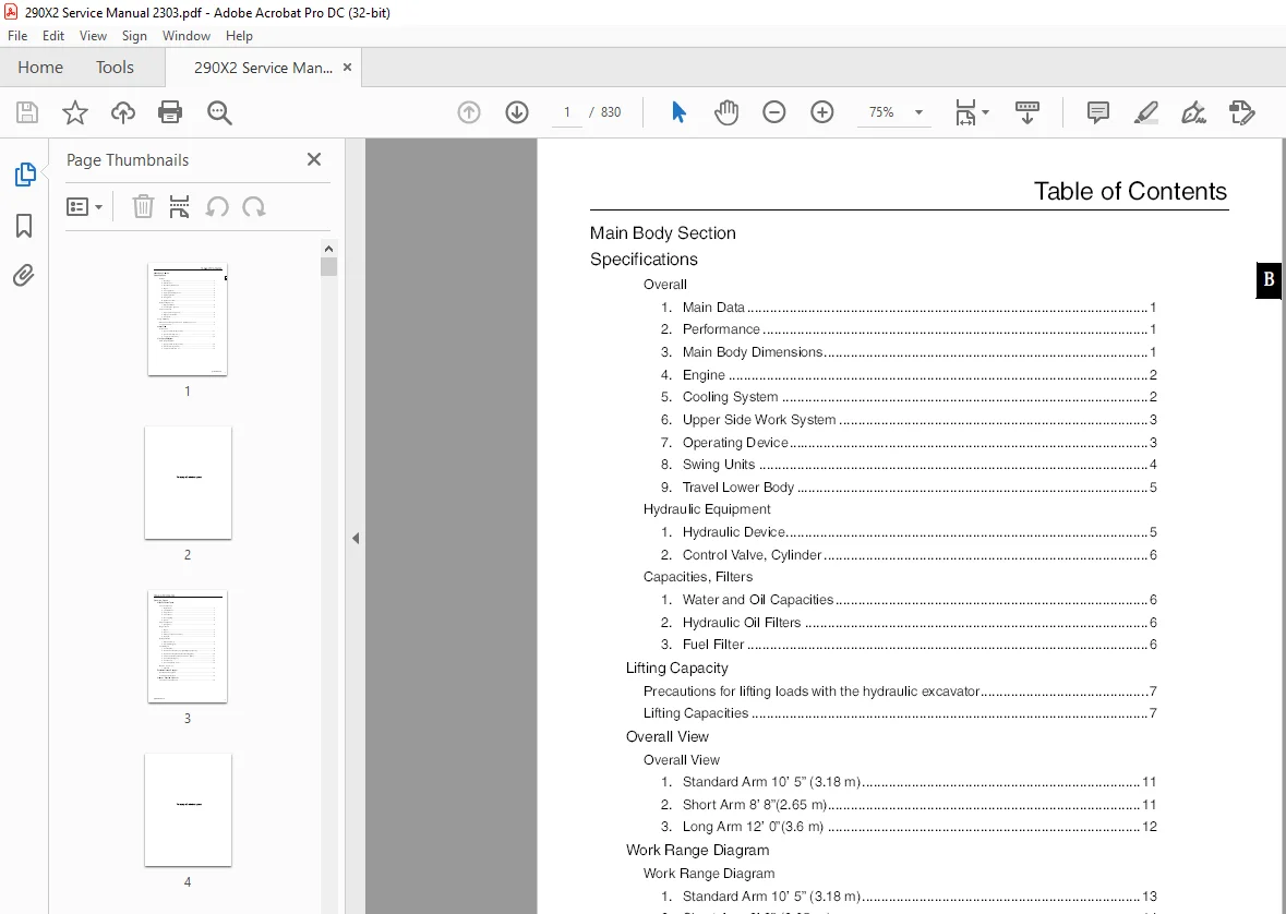
Pages : 830
Downloadable : Yes
File Type : PDF
IMAGES PREVIEW OF THE MANUAL:
DESCRIPTION:
Linkbelt 290-X2 Excavator Service Manual – PDF DOWNLOAD
Explanation of Hydraulic Circuit and Operations (standard model)
Travel Circuits
1. Travel Low-speed Circuit
As an example, this section explains the forward travel operation. The travel motor 2-stage tilt revolution angle is a large angle side. Even if the travel switch is set to the high-speed side, switching the key switch OFF, then ON again always returns the system to this state. By operating the travel remote control valve to the forward side, the pilot pressure oil is fed to the control valve Pa1 port and switches the left travel spool to the forward side. At the same time, the oil is also fed to the Pa6 port to switch the right travel spool to the forward side. The discharge oil from hydraulic pump A1 enters the control valve P1 port and the discharge oil from hydraulic pump A2 enters the control valve P2 port. Each flows to the respective travel motor and causes forward travel through the left and right travel spools being switched. The return oil from the travel motor goes through the left and right travel spools and returns to the hydraulic oil tank. The travel high-speed solenoid valve goes OFF, the travel motor P port oil connects with the tank line and the travel motor revolution tilt angle goes to the large revolution tilt side.
2. Boom-Up Circuit (compound boom-up + arm-in)
As an example, this section explains the boom-up + arm-in compound operation (leveling work). For leveling work, the boom-up pilot pressure oil is fed to the P2 port, the swing priority variable orifice is moved to the left side and the restriction on the flow to the arm is released to smooth the arm movement. By operating the remote control valve to the boom-up side and arm-in side, the pilot pressure oil is fed via the cushion valve to the control valve Pa4 port and Pb5 port and switches the boom (1) and arm (1) spools. At the same time, pressurized oil separated from the boom (1) side pilot internal path is fed from the P2 port to the P2 port and the swing priority variable orifice spool is switched to the left side. The discharge oil from hydraulic pump A1 enters the control valve P1 port and is fed from the parallel oil path to the boom (2) and arm (1) spools. Because the swing priority variable orifice spool in the parallel oil path is moved, the restriction on flow to the arm is released and the oil flows through the arm (1) spool and into the arm cylinder bottom side. This makes arm-in operation movement smooth. The arm cylinder rod side return oil goes through the load hold valve check valve and the arm (1) spool and returns to the hydraulic oil tank. The discharge oil from hydraulic pump A2 enters the control valve P2 port and is fed from the parallel oil path to the boom (1) spool. Switching the spool lets the oil flow through the boom load hold valve check valve and into the boom cylinder bottom side and carries out the boom-up operation. The boom cylinder rod side return oil goes through the boom (1) spool and returns to the hydraulic oil tank.
3. Boom-Down Regenerative Circuit
By moving the remote control valve to the boom down side, the pilot pressure oil is fed via the cushion valve to the control valve Pb8 port and switches the boom (1) spool to the down side. The discharge oil from hydraulic pump A2 enters the control valve P2 port and is fed from the parallel oil path to the boom (1) spool. Switching the spool lets the oil flow into the boom cylinder rod side and carries out the boom-down operation. The pilot pressure oil from the Pb8 port separated in the internal path is fed to the load hold valve spool and moves the spool to the left. In this way, the load hold valve check valve spring chamber oil is connected to the tank line through the load hold valve spool, the spring chamber pressure drops, and the load hold valve check valve is opened. The boom cylinder bottom side pressurized oil goes through the load hold valve check valve and is metered by the boom (1) spool regeneration orifice. Through this, the return oil pushes open the check valve in the spool and is regenerated on the cylinder rod side. The lower the cylinder rod side load pressure, the greater the volume of regeneration. When the cylinder rod side load pressure becomes high, the check valve is closed and the cylinder bottom return oil goes through the boom spool (1) without regeneration and returns to the hydraulic oil tank. Because the circuit is configured in such a way that even if the boom (1) spool is at full stroke, negative control pressure is generated by the center bypass bleed-off oil path and the pump does not discharge full flow and because the short fall is made up for with regeneration, engine output can be used effectively.
Questions? Email us: [email protected]
https://vimeo.com/892518770?share=copy
S.S