Linkbelt 350X2 Excavator Service Manual 2308 – PDF DOWNLOAD
Original price was: $75.95.$28.95Current price is: $28.95.
Linkbelt 350X2 Excavator Service Manual 2308 – PDF DOWNLOAD
Description
Linkbelt 350X2 Excavator Service Manual 2308 – PDF DOWNLOAD
FILE DETAILS:
Linkbelt 350X2 Excavator Service Manual 2308 – PDF DOWNLOAD
Language : English
Pages : 1154
Downloadable : Yes
File Type : PDF
Size: 65.1 MB
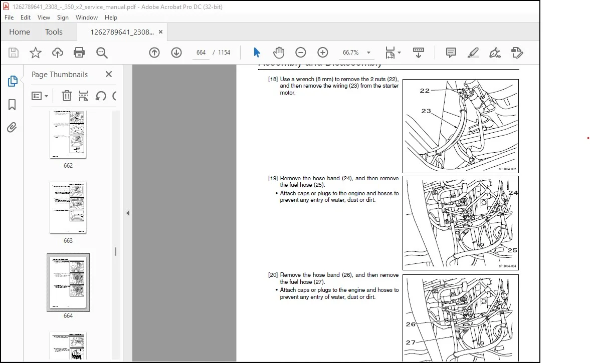
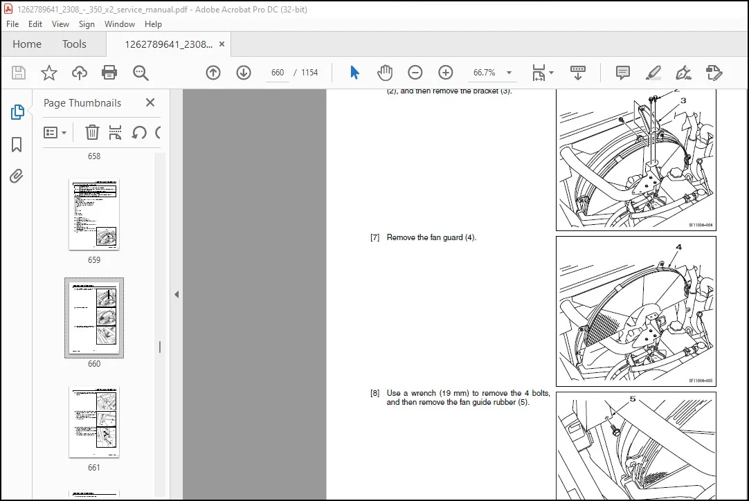
IMAGES PREVIEW OF THE MANUAL:
Questions? Email us: [email protected]
https://vimeo.com/770614399
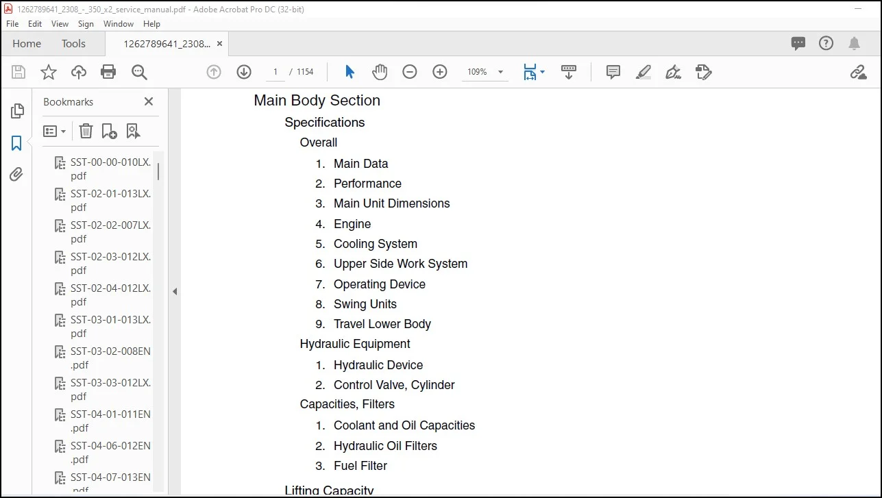
TABLE OF CONTENTS:
Linkbelt 350X2 Excavator Service Manual 2308 – PDF DOWNLOAD
Main Body Section
Specifications
Overall
1. Main Data
2. Performance
3. Main Unit Dimensions
4. Engine
5. Cooling System
6. Upper Side Work System
7. Operating Device
8. Swing Units
9. Travel Lower Body
Hydraulic Equipment
1. Hydraulic Device
2. Control Valve, Cylinder
Capacities, Filters
1. Coolant and Oil Capacities
2. Hydraulic Oil Filters
3. Fuel Filter
Lifting Capacity
Precautions for lifting loads with the hydraulic excavator
Lifting Capacities (Standard Arm)
Lifting Capacities (Short Arm)
Lifting Capacities (Long Arm)
Overall View
Overall View (350X2)
1. Standard Arm (3.25 m)
2. Short Arm (2.63 m)
3. Long Arm (4.04 m)
Work Range Diagram
Work Range Diagram (350X2)
1. Standard Arm (3.25 m)
2. Short Arm (2.63 m)
3. Long Arm (4.04 m)
1
SST-00-00-010LX
Contents
Summary Section
Main Equipment Table
Lower Component
1. Travel Unit
2. Take-up Roller
3. Upper Roller
4. Lower Roller
5. Recoil Spring
6. Shoe
Upper Component
1. Swing Unit
Engine-related
1. Engine
2. Muffler
3. Air Cleaner (double element)
4. Radiator
Hydraulic Device
1. Hydraulic Pump
2. Pump P-Q Diagram
Control-related
1. Control Valve
2. Solenoid Valve (5 stack)
3. Remote Control Valve (left/right, travel operations)
4. Remote Control Valve Characteristic Diagram
5. Cushion Valve (heat circuit, with shuttle valve)
6. Selector Valve (option)
7. Center Joint
Backhoe Attachment
1. Cylinder
2. Attachments
Equipment Layout Diagram
Main Equipment Layout
Consumable Part Layout
Standard Machine Option List
List of Optional Components
2
Contents
SST-00-00-010LX
Hydraulics Section
Hydraulic Equipment Layout
Overall View
Pump Chamber Hydraulic Equipment Layout
Swing Body Center Section Hydraulic Equipment Layout
Housing Left Side Hydraulic Equipment Layout
Layout of Hydraulic Equipment in Cab
Port Diagram
Pump
1. Hydraulic Pump (standard model)
Valves
1. Control Valve
2. 5 Stack Solenoid Valve
3. 2 Stack Solenoid Valve
4. Remote Control Valves (upper, travel)
5. Cushion Valve
6. 4-way Multi-valve
7. 2-way Multi-valve
8. Direction Valve/Shut-off Valve
9. HBCV (Option)
Manifolds
1. Manifold Under Cab
2. Manifold (accumulator section)
3. Manifold (hydraulic oil tank section)
Motors
1. Swing Motor
2. Travel Motor
3. Center Joint
Pilot Hose Connection Diagram
Pilot P and T Lines
Pilot Control Line
Pilot Control Line (2-way selector valve)
Pilot Control Line (4-way selector valve)
Function List
Function Table
Explanation of New Functions
1. Swing Relief Cut-off Control
2. Swing Speed Limit Control
3
SST-00-00-010LX
Contents
3. Negative Control Power Save Control
4. Option Line Flow Adjustment Control
5. Multi Purpose Circuit (breaker ⇔ crusher) One-touch Switching Control
6. Bucket-close Regenerative Circuit
Explanation of Hydraulic Circuit and Operations (standard model)
Travel Circuit
Travel low-speed circuit
Travel high-speed circuit
Straight travel circuit
Swing Circuit
Swing speed limit control circuit
Swing relief cut-off control circuit
Swing priority circuit
Swing brake circuit
Swing parking circuit (lever in neutral)
Swing parking circuit (brake release)
Swing parking circuit (machine stop)
Boom Circuit
Boom-up circuit (independent operation)
Boom-up circuit (compound boom-up + arm-in)
Boom-down regenerative circuit
Boom-down tilting prevention circuit
Boom-down load holding valve circuit
Arm Circuit
Arm-out circuit
Arm-in forced regenerative circuit
Arm-in load holding valve circuit
Bucket Circuit
Bucket-open circuit
Bucket-close regenerative circuit
Negative Control Circuit
Negative control circuit (power save solenoid OFF)
Negative control power save circuit (power save solenoid ON)
Negative control circuit (bucket close, power save solenoid OFF)
Other Circuits
Cushion circuit (arm-out operation)
Cushion circuit (arm-out operation stopped)
Cushion circuit (arm-out → arm-in operation)
Heat circuit (lever in neutral)
Auto pressure boost circuit (bucket close)
4
Contents
SST-00-00-010LX
Explanation of Hydraulic Circuit and Operations (option)
Option Circuits
Breaker circuit (independent operation)
Double-acting circuit (hydraulic fork)
Multi-purpose circuit (breaker Q control)
Multi-purpose circuit (2 pumps flow crusher)
2nd option circuit (hydraulic rotation fork)
Main Equipment Structure and Operation Explanation
Pump
1. Hydraulic Pump
2. Regulator
3. Gear Pump
Motor
1. Travel Motor
2. Swing Motor
Valve
1. Control Valve
2. 5 Stack Solenoid Valve Operation Explanation
3. Upper Pilot Valve (remote control valve)
4. Travel Pilot Valve (remote control valve)
5. Cushion Valve
6. Selector Valve (4-way)
7. Direction Valve (3-direction)
5
SST-00-00-010LX
Contents
Electrics Section
Explanation of New Functions
Work Mode Select Switch
The Throttle Volume and Work Mode Select Switch are Linked!!
Computer connection method
Monitor changes
Pilot pressure switch changed to pressure sensor
Pump Electromagnetic Proportional Valve
1. Horsepower Control Proportional Valve
2. P1 Flow Control Proportional Valve
System Control for Energy Saving
1. Reduced Fuel Consumption Through Transient Load Reduction Control
2. Reduced Fuel Consumption Through Swing Relief Cut Control
3. Reduced Fuel Consumption Through Power Save Control
Swing Speed Limit Control
Electrical Equipment Layout Diagram
Overall View
1. Main Unit Left Side Layout Diagram (radiator chamber)
2. Engine Section Layout Diagram
3. Main Unit Right Side Layout Diagram (pump chamber)
4. Main Unit Center Section Layout Diagram
5. Cab Layout Diagram 1
6. Layout Around Operator’s Seat
Stand Alone Parts Diagram
Main Equipment Structural Diagrams
Connection Connector Pin Layout
1. Computer A
2. Monitor
Electrical Circuit Diagram
Overall View
1. Sequence Circuit Diagram
6
Contents
SST-00-00-010LX
Block Diagram
1. Computer A
2. Computer S
3. ECM
4. Monitor Display
5. Air Conditioner
6. Lever Lock
7. Horn
8. Working Light
9. Option
10. Other
11. Electrical Symbol List
Electrical Connector Wiring Diagram
Wire Harness
1. Main Frame Harness
Cab
1. Cab Main Harness
2. Cab Sub Harness
3. In Cab
4. Engine Harness
Console
1. Console Right Harness
2. Console Left Harness
Electrical Parts and Wiring Assembly Diagram
Main Frame
Cab
Explanation of Functions and Operations
Explanation of Electrical Functions
Engine Speed Control
1. Throttle Control
2. Idling Control (auto/one-touch)
3. Idling Start
4. Auto Warm-up
Engine Start/Stop Control
1. Engine Start/Stop Judgment
2. Power-cut Delay
3. Engine Emergency Stop
4. Neutral Start
7
SST-00-00-010LX
Contents
Pump Control
1. Work Mode Control
2. Pump Horsepower Boost Control
3. Pump Horsepower Cut Control
4. Power Save Control
Swing
1. Swing Brake
2. Swing Free Swing (option for North America)
3. Swing Lock (for maintenance)
4. Swing Relief Cut
5. Swing Speed Limit
Travel
1. Travel Speed Switchover
2. Travel Alarm
Valve Control
1. Lever Lock
2. Solenoid Sticking Prevention
3. Pressure Boost Control
Monitor Control
1. Bar Graph (coolant temperature gauge, oil temperature gauge, fuel gauge)
Accessories
1. Horn
2. Working Light
3. Wiper and Washer
4. Room Lamp
5. Radio Mute
Other
1. Anti-theft
2. Battery Save Function
3. Alternator Power Generation Detection
4. Overload Warning
Options
1. Option line control
2. Option Line Control
3. Feed Pump Automatic Stop
4. Return Filter Clogging Detected
5. Beacon
8
Contents
SST-00-00-010LX
Service Support
Screen Operations
1. Screen Shift
Screen Display List
1. CHK (status display) Screen List
2. DIAG (trouble diagnosis) Screen
3. HR (usage log) Screen List
4. CFG (setting change) Screen
5. CAL (troubleshooting support) Screen
6. Check the Monitor Switch (self-diagnosis function)
7. Option Flow Setting
8. Anti-theft Setting
9. Model Setting
10. Engine Information Screen
Screen Display Details
1. Message Display List
Abnormality Display
1. Diagnostic Trouble Code Display
2. Main Unit Diagnostic Trouble Code List
3. Diagnostic Trouble Code (monitor display)
4. Sensor Trouble Operation Table
5. EPF (Engine Protection Feature)
9
SST-00-00-010LX
Contents
Engine Section
Engine Summary
Main Data Table
Overall Appearance Diagram
Sensor and Auxiliary Equipment Layout (left)
Sensor and Auxiliary Equipment Layout (rear)
Engine System Diagram
Fuel System Diagram
Detailed Parts Diagrams
1. ECM (engine control module)
2. Supply Pump/SCV (suction control valve)
3. Common Rail/Flow Damper
4. Common Rail Pressure Sensor/Pressure Limiter
5. Injector
6. Engine Coolant Temperature Sensor
7. Engine Oil Pressure Sensor
8. Cam Position Sensor (CMP sensor)
9. Crank Position Sensor (CKP sensor)
10. Atmospheric Pressure Sensor
11. Suction Air Temperature Sensor
12. Boost Pressure Sensor
13. Boost Temperature Sensor
14. Charge Fuel Pump
15.EGR Cooler
16. Lead Valve (check valve)
17.EGR Valve
Engine Control Summary
Explanation of Engine Terms
Function Explanation Table
Explanation of Engine Structure
Technology for Exhaust Gases
1. Common Rail System
2. Multi Stage Fuel Injection (multiple injection)
3. Inter Cooler
4. EGR (exhaust gas recirculation)
10
Contents
SST-00-00-010LX
Explanation of Engine Operation
Fuel Unit
1. Common Rail System Summary
2. Change Points for Injection Method (governor, common rail)
3. Explanation of Injector Operation
4. Explanation of Supply Pump Operation
5. Supply Pump Disassembly Diagram
6. Explanation of Flow Damper Operation
7. Pressure Limiter
8. Cautions for Maintenance
Explanation of Engine Control
1. Fuel Injection Quantity Correction
2. Starting Q Correction
3. Preheat Control (QOS: quick on start)
4. Atmospheric Pressure Correction (high altitude correction)
5. Control for Overheating
6. Control for Boost Temperature Rise
7. Control for Engine Oil Pressure Drop
8. Start Control (coolant temperature monitoring)
9. Long Cranking Control
10. Starting Control for Reduced Number of Cylinders
11. Normal Stop (key switch OFF operation)
12. Engine Start/Stop Judgment
Engine Maintenance Standards
Engine Information Screen
1. Purpose
2. How to Go to This Screen
3. Engine Start Restriction
4. Screen
Monitor Operating Method
1. View Mode
2. Edit Mode
Engine Information
(Q resistance, QR code, engine serial number) Copying Method
Rewriting Injector QR Codes
When Replacing Computer A at the Same Time
Engine Information Acquisition Timing
Redoing Engine Information Acquisition
Abnormality Display
11
SST-00-00-010LX
Contents
Engine Equipment Table
Exhaust Gas 3rd Engine Accessory Electrical Parts Interchangeability (Isuzu part number)
Exhaust Gas Regulations
Features of Materials Subject to Exhaust Gas Regulation
Exhaust Gas Regulation Values
Cautions for Fuel Used
Engine Fuel and Maintenance of Fuel Filters
1. Fuel to be applied
2. Maintenance of fuel filters
12
Contents
SST-00-00-010LX
Air Conditioner Section
Layout Diagram
Air Conditioner Overall Diagram
1. Frame
2. Cab
Equipment Layout Diagram
Circuit Diagram
Air Conditioner Circuit Diagram
Explanation of Functions
Explanation of Control
1. Air Mix Motor Actuator Control
2. Blow Mode Motor Actuator Control
3. Refresh / Recirculate Switch Motor Actuator Control
4. Blower Amp Control
5. Compressor Clutch Control
6. COOLMAX Control and HOTMAX Control
7. Trouble Detection and Control after Trouble Detected
8. Monitor Mode
9. Door Switch Control
10. Inside Air Filter Clogging Detection Control
Actuator Inspection
Air Mix Motor Actuator Inspection
Refresh / Recirculate Motor Actuator Inspection
Mode Motor Actuator Inspection
Self-diagnosis Function with Panel Display
Abnormality Display and Self-check Procedures
1. Abnormality Display Position
2. Explanation of Abnormality Display
3. Explanation of Monitor Mode
Part Function and OK/NG Judgment
Control Panel and Control Unit
Blower Amp
Relay
Air Mix Actuator
Refresh / Recirculate Actuator
Blow Mode Actuator
Evaporator Sensor
Dual Pressure Switch
Solar Radiation Sensor
PLEASE NOTE:
- This is the SAME exact manual used by your dealers to fix your vehicle.
- The same can be yours in the next 2-3 mins as you will be directed to the download page immediately after paying for the manual.
- Any queries / doubts regarding your purchase, please feel free to contact [email protected]
S.V