Linkbelt 4300 Excavator Quantum Shop Manual 836 – PDF DOWNLOAD
$23.95
Linkbelt 4300 Quantum Excavator Shop Manual 836 – PDF DOWNLOAD
Description
Linkbelt 4300 Quantum Excavator Shop Manual 836 – PDF DOWNLOAD
FILE DETAILS:
Linkbelt 4300 Quantum Excavator Shop Manual 836 – PDF DOWNLOAD
Language : English
Pages : 190
Downloadable : Yes
File Type : PDF
IMAGES PREVIEW OF THE MANUAL:
DESCRIPTION:
Linkbelt 4300 Quantum Excavator Shop Manual 836 – PDF DOWNLOAD
Service Manual
Track Installation
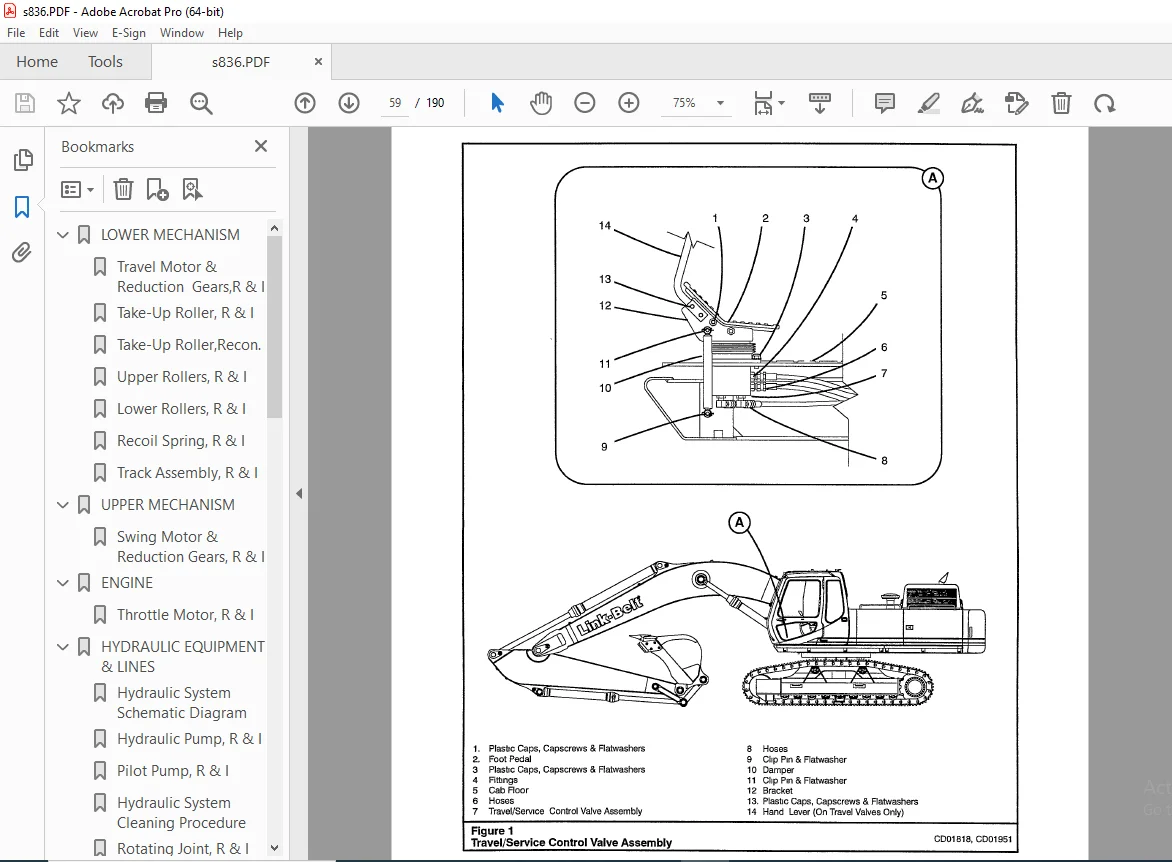
1. Use an auxiliary lifting device of sufficient capacity to support the weight of the track (5) assembly. Position the track (5) assembly under the machine and align the track links (10) to the sprocket (7) and take-up roller (6).
2. Connect a chain (4) to the end of track (5) at the sprocket (7) and bucket (3).
3. Start the engine and drive the track (5) being installed in forward, while moving the boom (1) and arm (2) up and out at the same time. Keep the track tight and level.
4. Allow the end of the track to go over the upper rollers (8) and into position on the center/front of the take-up roller (6).
5. Remove chain (4).
6. Rotate the upper so that the cab 1s over the track that was just installed.
7. Check the position of the track (5) assembly under the machine and align the track links (10) to the take-up roller (6) if necessary.
8. Remove supports (17) from lower frame (18).
9. Lower machine down onto track (5) assembly.
10. Connect suitable pulling equipment to both ends of the track (5).
11. Pull track (5) together until master pin (14) holes align.
12. Install spacers (15) and sleeve (16) into track links (10).
13. Using a portable hydraulic track press, install master pin (14).
14. Install retainer (9) into master pin (14).
15. Install track shoes (11) onto track links (10), using capscrews (12) and nuts (13). Torque nuts (13) to 557-687 ft-lb (755-932 Nm).
16. Adjust track tension. See Operator’s Manual for track tension adjustment procedures.
17. Test all hydraulic functions prior to returning machine to service.
TABLE OF CONTENTS:
Linkbelt 4300 Quantum Excavator Shop Manual 836 – PDF DOWNLOAD
LOWER MECHANISM.............................................  3
	Travel Motor & Reduction  Gears,R & I...................  5
	Take-Up Roller, R & I................................... 13
	Take-Up Roller,Recon.................................... 17
	Upper Rollers, R & I.................................... 19
	Lower Rollers, R & I.................................... 21
	Recoil Spring, R & I.................................... 23
	Track Assembly, R & I................................... 27
UPPER MECHANISM............................................. 33
	Swing Motor & Reduction Gears, R & I.................... 33
ENGINE...................................................... 37
	Throttle Motor, R & I................................... 37
HYDRAULIC EQUIPMENT & LINES................................. 41
	Hydraulic System Schematic Diagram...................... 41
	Hydraulic Pump, R & I................................... 43
	Pilot Pump, R & I....................................... 49
	Hydraulic System Cleaning Procedure..................... 51
	Rotating Joint, R & I................................... 53
CONTROLS.................................................... 55
	Joystick Control Valve, R & I........................... 55
	Travel/Service Control Valve, R & I..................... 59
	Main Control Valve, R & I............................... 61
ATTACHMENT.................................................. 65
	Boom Cylinder, R & I.................................... 65
	Arm Cylinder, R & I..................................... 69
	Bucket Cylinder, R & I.................................. 73
ELECTRIC PARTS.............................................. 77
	Electrical System Schematic Diagram With Heavy Lift..... 77
	Electrical System Schematic Diagram With Power Boost.... 79
	Monitor System Controller, R & I/Adjustment............. 81
NAME PLATES & ACCESSORIES................................... 87
	Capscrew Torques........................................ 87
	Spare Pump, R & I....................................... 91
	INNER PARTS............................................. 93
	Hydraulic Pump Troubleshooting.......................... 93
	Spare Pump, Recon....................................... 95
	Pilot Pump, Recon.......................................105
	Hydraulic Pump, Recon...................................109
	Travel Motor, Recon.....................................137
	Travel Motor Reduction Gears, Recon.....................141
	Swing Motor, Recon......................................145
	Swing Motor Troubleshooting.............................149
	Swing Reduction Gears, Recon............................153
	Main Control Valve, Recon...............................159
	Boom Cylinder, Recon....................................169
	Arm Cylinder, Recon.....................................173
	Bucket Cylinder, Recon..................................177
	Joystick Control Valve, Recon...........................181
	Travel/Service Valve Control Valve, Recon...............185
	Rotating Joint, Recon...................................187
	8 Spool Solenoid Valve Assembly, Recon..................189
Customer Support: [email protected]
https://vimeo.com/892625027?share=copy
S.S