Linkbelt 470X3 Excavator Service Manual WLSM4706-08LX – PDF DOWNLOAD
Original price was: $75.95.$34.95Current price is: $34.95.
Linkbelt 470X3 Excavator Service Manual WLSM4706-08LX – PDF DOWNLOAD
Description
Linkbelt 470X3 Excavator Service Manual WLSM4706-08LX – PDF DOWNLOAD
FILE DETAILS:
Linkbelt 470X3 Excavator Service Manual WLSM4706-08LX – PDF DOWNLOAD
Language : English
Pages : 1471
Downloadable : Yes
File Type : PDF
Size: 100 MB
IMAGES PREVIEW OF THE MANUAL:
Need help? Contact: [email protected]
https://vimeo.com/770395724
DESCRIPTION:
Linkbelt 470X3 Excavator Service Manual WLSM4706-08LX – PDF DOWNLOAD
General Information:
Cleaning:
Clean the metal parts with cleaning solution that meets the standard and steam cleaning. (except for bearings) After cleaning, dry well, and inject oil in all parts. Also inject oil into the bearings after drying.
Inspection:
When disassembling parts, check all the parts. If there are any worn or damaged parts, replace them. Inspect carefully to prevent initial breakdowns.
Bearing:
Replace any loose bearings. Air dry bearings before installing them.
Needle bearing:
When inserting needle bearings, be very careful not to damage them. Apply grease to the section where the needle bearing will be inserted.
Gear:
Check that there is no wear and no damage.
Oil seal, O-ring, gasket:
Always install new oil seals, O-rings, and gaskets. Apply grease to sections where oil seals
and O-rings will be inserted.
Shaft:
Check that there is no wear and no damage. Check the bearings and check for damaged
oil seals on the shaft.
TABLE OF CONTENTS:
Linkbelt 470X3 Excavator Service Manual WLSM4706-08LX – PDF DOWNLOAD
Excavator 1
SAFETY 7
SAFETY, GENERAL INFORMATION AND STANDARD TORQUE DATA 10
General Information 11
Safety 11
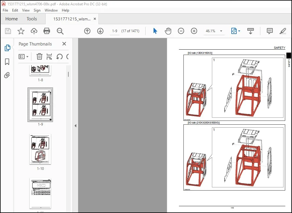
ROPS 14
ROPS Judgment Method 14
Standard Torque Data For Cap Screws And Nuts 19
Bolt and Nut Tightening 19
A LOWER 21
Specifications 25
470X3 25
Travel Lower Body 25
Main Equipment Table 26
470X3 26
Lower Component 26
Travel Unit 26
Take-up Roller 26
Upper Roller 26
Lower Roller 26
Recoil Spring 26
Shoe 27
Center Joint 27
Main Equipment Structure and Operation Explanation 28
Travel Motor 28
Travel motor operation explanation 28
Structure 28
Summary explanation of component parts 29
Rotary group 29
Parking Brake 29
Variable Capacity Mechanism Section 29
Overload Relief Valve 30
Brake Valve Section 31
Function 32
Motor operation 32
Parking Brake Operation 33
Operation of Variable Capacity Mechanism Section 34
Overload Relief Valve Operation 36
Brake Valve Operation 37
Port Diagram 41
Travel Motor 41
Center Joint 42
Basic Functions 43
Travel Speed Selection 43
Travel Alarm 45
Removal and Installation of Track 47
Removal and Installation of Shoe Assembly 47
Removal of Shoe Assembly 47
Installation of Shoe Assembly 49
Removal and Installation of Shoe Plate 50
Removal of Shoe Plate 50
Installation of Shoe Plate 50
Precautions for Shoe Bolt Installation 51
Removal and Installation of Roller 52
Removal and Installation of Upper Roller 52
Removal of Upper Roller 52
Installation of Upper Roller 53
Assembly and Disassembly of Upper Roller 54
Configuration Diagram 54
Dimension Diagram 55
Jig Dimension Diagram 55
Disassembly Procedures 55
Assembly Procedures 57
Removal and Installation of Lower Roller 59
Removal of Lower Roller 60
Installation of Lower Roller 60
Assembly and Disassembly of Lower Roller 61
Configuration Diagram 62
Dimension Diagram 62
Jig Dimension Diagram 63
Disassembly Procedures 63
Assembly Procedures 65
Removal and Installation of Retractable Lower Frame 68
Removal of Retractable Lower Frame 68
Installation of Retractable Lower Frame 69
Removal and Installation of Drive Sprocket 70
Removal of Drive Sprocket 70
Installation of Drive Sprocket 71
Removal and Installation of Take-up Roller 72
Removal of Take-up Roller 72
Installation of Take-up Roller 73
Assembly and Disassembly of Take-up Roller 74
Configuration Diagram 75
Dimension Diagram 75
Jig Dimension Diagram 75
Disassembly Procedures 76
Assembly Procedures 77
Removal and Installation of Grease Cylinder 80
Removal of Grease Cylinder 80
Installation of grease cylinder 81
Assembly and Disassembly of Grease Cylinder 82
Configuration Diagram 82
Dimension Diagram 82
Jig Dimension Diagram 83
Disassembly Procedures 83
Assembly Procedures 83
Removal and Installation of Center Joint 85
Removal of Center Joint 85
Installation of Center Joint 87
Assembly and Disassembly of Center Joint 88
Configuration Diagram 89
Dimension Diagram 90
Jig Dimension Diagram 91
Disassembly Procedures 91
Assembly Procedures 92
Removal and Installation of Travel Motor 96
Removal of Travel Motor 96
Installation of Travel Motor 98
Assembly and Disassembly of Travel Motor 101
Tools for Assembly and Disassembly 101
Standard tools 101
Secondary Materials 101
Special Tool (jig) 102
Measurement Device 105
Motor Disassembly Procedures 106
Precautions before motor disassembly 106
Tightening Torque 106
Disassembly procedure 107
Removal of supplied valves 107
Disassembly of motor 107
Disassembly of overload relief valve 111
Reduction gear disassembly procedures 111
Disassembly preparations 111
Disassembly procedure 112
Installation to Receiving Platform Of Reduction Gear (unit) 112
Removal of Reduction Gear Cover 112
Removal of carrier 1 assembly 112
Removal of carrier 2 assembly 113
Removal of housing assembly 113
Disassembly of Housing Assembly 114
Removal of floating seal from motor 115
Disassembly of carrier 1 assembly 115
Disassembly of Carrier 2 Assembly 115
Maintenance standards 117
Motor Parts Maintenance Standards 117
Reduction gear parts maintenance standards 119
Inspection prior to reassembly 119
Thrust washer 119
Gears 120
Bearing 120
Floating seal 120
Parts Maintenance 120
Assembly of motor 121
Precautions before Motor Assembly 121
Assembly procedure 121
Motor Assembly Procedures 121
Motor assembly procedure 125
Assembly of the Carrier 2 Assembly 125
Assembly of the carrier 1 assembly 126
Installation of bearing and floating seal 126
Assembly of the housing assembly 126
Determining the thickness of the angular bearing shim 127
Installation of housing assembly 128
Installation of Carrier 2 Assembly 129
Installation of carrier 1 assembly 129
Cover Attachment 130
Gear Oil Filling 130
Initial pre-conditioning operation 131
Drain charge 131
Performing initial operation (pre-conditioning operation) 131
Troubleshooting 132
General cautions 132
Causes of troubles and countermeasures 132
Structural diagram 135
Travel Motor 135
Reduction Gear 137
Maintenance Standards 139
Drive Sprocket 139
Take-up Roller 140
Upper Roller 141
Lower Roller 143
Track Shoe (grouser shoe) 144
Inspection Gauge 146
For Drive Sprocket 146
For Take-up Roller 146
For Upper Roller 147
For Lower Roller 147
Pressure Measurement and Adjustment Procedures 148
Main Pressure Measurement 148
B Travel Pressure Measurement 148
Drain Volume Measurement Procedures 149
Preparations 149
Travel Motor Drain Volume Measurement 149
Air Bleed Procedure 151
Travel Motor 151
B C SWING UNIT, COUNTERWEIGHT 153
Specifications 156
470X3 156
Upper Side Work System 156
Swing Units 157
Main Equipment Table 158
470X3 158
Upper Component 158
Swing Unit 158
Main Equipment Structure and Operation Explanation 159
Swing Motor 159
Swing Motor Operation Explanation 159
Hydraulic Motor Operation Explanation 159
Mechanical Brake Operation Explanation 159
Make-up Valve Operation Explanation 160
Relief Valve Operation Explanation (relief valve internal structure diagram) 160
Bypass Valve Operation Explanation (bypass valve internal structure diagram) 162
Swing motor internal diagram 163
Port Diagram 165
Swing Motor 165
Basic Functions 166
Swing Brake 166
Swing Lock 167
Swing Speed Limit 168
Free Swing (option) 169
Removal and Installation of Swing Unit 170
Removal of Swing Unit 170
Installation of Swing Unit 172
Assembly and Disassembly of Swing Motor 173
Causes of Trouble and Solutions 174
Maintenance Standard Table 176
Jig 177
Disassembly 177
Assembly 182
Swing Motor Internal Structural Diagram 189
Assembly and Disassembly of Swing Unit 191
Disassembly 191
Assembly 192
Assembly and Disassembly of Swing Reduction Gear 194
Disassembly 194
Assembly 196
Swing Reduction Gear Structure Diagram 202
Removal and Installation of Counterweight 204
Removal of Counterweight 204
Installation of Counterweight 205
Pressure Measurement and Adjustment Procedures 206
Main Pressure Measurement 206
C Swing Pressure Measurement 206
Drain Volume Measurement Procedures 207
Preparations 207
Swing Motor Drain Volume Measurement 207
Air Bleed Procedure 208
Swing Motor 208
H ENGINE 209
Specifications 214
470X3 214
Engine 214
Cooling System 214
Capacities, Filters 215
Coolant and Oil Capacities 215
Fuel Filter 215
Main Equipment Table 216
470X3 216
Engine-related 216
Engine 216
DPD 216
Air Cleaner (double element) 216
Radiator 217
Basic Functions 218
Fuel Gauge 218
Coolant Temperature Gauge 220
DPD Gauge 222
Fuel Economy Gauge 223
Neutral Start 224
Engine Start/Stop Control 225
Power-cut Delay 226
Preheating 227
Throttle 228
Engine Throttle Switch Position Detection 229
Idling Start 234
Auto Idle 235
One-touch Idle 236
Auto Warm Up 237
Quick Warm Up 238
Idling Stop 240
Idle up 241
Work Mode Control 242
Engine Emergency Stop 244
Coolant Level Reduction 244
Air Filter Clogged 245
Fuel Filter Clog 246
DPD Regeneration 246
Automatic Regeneration 248
Manual Regeneration 250
Optional Manual Regeneration 252
Hydraulic Assisting Load 254
Primary specifications 255
Function, Structure, and Operations 257
Symptom 310
Frequent Manual DPD Regeneration 310
DPD Regeneration Taking Excessively Long 311
Engine Start Problems 312
Engine Stalling 314
Engine Hunting, Rough Idling 316
Excess Amount of White Smoke in Exhaust Gas 317
Excess Amount of Black Smoke in Exhaust Gas 318
Abnormal Noise 318
Large fuel consumption 319
Large oil consumption 320
Engine Output Deficiency 321
Functional Inspection 323
Inspection of the scan tool power circuit system 323
Inspection of the starter circuit system 323
Compression pressure inspection 324
Inspection of the starting system 325
Inspection of the fuel system 326
Inspection of the air intake system 327
Inspection of the exhaust system 327
Inspection of EGR Control System 327
Inspection of the glow control system 328
DPD Function Inspection 329
OBD System Check 331
Inspection of the diagnostic light warning light illumination circuit system 332
Inspection of the monitor warning light blinking circuit system 332
Inspection of Scan Tool Power Supply System 333
Maintenance precautions 334
Removal and Installation of Engine Assembly 337
Removal of Engine Assembly 337
Installation of Engine Assembly 342
Removal and Installation of Fuel Cooler, Engine Intercooler, Radiator, and Oil Cooler 343
Removal and Installation of Fuel Cooler 343
Removal of Fuel Cooler 343
Installation of Fuel Cooler 343
Removal and Installation of Engine Intercooler 344
Removal of Intercooler 344
Installation of Inter Cooler 344
Removal and Installation of Radiator 345
Removal of Radiator 345
Installation of Radiator 348
Removal and Installation of Oil Cooler 348
Removal of Oil Cooler 348
Installation of oil cooler 350
Removal and Installation of Hydraulic Drive Fan 351
Removal of Hydraulic Drive Fan 351
Installation of Hydraulic Drive Fan 352
Removal and Installation of Turbocharger assembly 353
Turbocharger assembly Removal 353
Turbocharger assembly Installation 354
Removal and Installation of EGR valve 357
EGR valve Removal 357
EGR valve Installation 358
Removal and Installation of Engine Hood 362
Removal of Engine Hood 362
Installation of Engine Hood 363
Removal and Installation of Muffler 364
Removal of Muffler 364
Installation of Muffler 364
Removal and Installation of Cylinder head cover 365
Cylinder head cover Removal 365
Cylinder head cover Installation 365
Removal and Installation of Cylinder head 366
Cylinder head assembly Removal 366
Cylinder head assembly Disassembly 372
Cylinder head assembly Reassembly 375
Cylinder head assembly installation 380
Cylinder head assembly Inspection 395
Removal and Installation of Cylinder block 402
Cylinder block Removal 402
Cylinder block installation 414
Cylinder block Inspection 443
Lubrication System 445
Removal and Installation of Oil pan 445
Oil pan Removal 445
Oil pan Installation 445
Removal and Installation of Oil level switch 445
Oil level switch Removal 445
Oil level switch Installation 446
Removal and Installation of Oil pump assembly 446
Oil pump assembly Removal 446
Oil pump assembly Disassembly 446
Oil pump assembly Reassembly 447
Oil pump assembly Installation 447
Oil pump assembly Inspection 448
Engine oil Inspection 448
Cooling System 450
Removal and Installation of Water pump assembly 450
Water pump assembly Removal 450
Water pump assembly Installation 451
Water pump assembly Inspection 455
Removal and Installation of Thermostat 456
Thermostat Removal 456
Thermostat Installation 458
Thermostat Inspection 462
Coolant Inspection 462
Removal and Installation of Overheat switch 464
Overheat switch Removal 464
Overheat switch Installation 464
Disassembly, Removal and Installation of DPD assembly 465
Disassembly of DPD Assembly 465
DPD assembly Reassembly 466
DPD assembly Inspection 468
Removal and Installation of Fuel Tank 470
Removal of Fuel Tank 470
Installation of fuel tank 472
Removal and Installation of Fuel supply pump 473
Fuel supply pump Removal 473
Fuel supply pump Installation 475
Removal and Installation of Common rail assembly 483
Removal of Common Rail Assembly 483
Common rail assembly Installation 484
Removal and Installation of Injector 487
Injector Removal 487
Injector Installation 490
Removal and Installation of Starter Motor 496
Removal of Starter Motor 496
Installation of Starter Motor 497
Removal and Installation of Alternator 498
Removal of Alternator 498
Installation of Alternator 498
Preheating System 499
Removal and Installation of Glow plug 499
Glow plug Removal 499
Glow plug Installation 500
Glow plug Inspection 503
Introduction to the trouble diagnosis 504
Removal and Installation of Fuel filter pressure sensor 512
Fuel filter pressure sensor Removal 512
Fuel filter pressure sensor Installation 513
Removal and Installation of Engine coolant temperature sensor 513
Engine coolant temperature sensor Removal 513
Engine coolant temperature sensor Installation 514
Engine coolant temperature sensor Inspection 514
Removal and Installation of CKP sensor 515
CKP sensor Removal 515
CKP sensor Installation 515
CKP sensor Inspection 515
Removal and Installation of CMP sensor 515
CMP sensor Removal 515
CMP sensor Installation 515
CMP sensor Inspection 516
Removal and Installation of Oil pressure sensor 516
Oil pressure sensor Removal 516
Oil pressure sensor Installation 516
Removal and Installation of Boost sensor 516
Boost sensor Removal 516
Boost sensor Installation 516
Removal and Installation of Boost temperature sensor 517
Boost temperature sensor Removal 517
Boost temperature sensor Installation 517
Removal and Installation of IMT sensor 517
IMT sensor Removal 517
IMT sensor Installation 517
Removal and Installation of Exhaust differential pressure sensor 518
Exhaust differential pressure sensor Removal 518
Exhaust differential pressure sensor Installation 519
Exhaust differential pressure sensor Inspection 519
Removal and Installation of Exhaust gas temperature sensor 520
Removal of Exhaust Gas Temperature Sensor 520
Exhaust gas temperature sensor Installation 520
Exhaust gas temperature sensor Inspection 521
Engine-side Diagnostic Trouble Code List 522
Troubleshooting – engine 525
Engine-side Trouble 525
Diagnostic Trouble Code 0016 Abnormally Correlation Between Crankshaft Position and Camshaft Position 525
Diagnostic trouble code 0045 Turbocharger Boost Pressure Control System Abnormality 526
Diagnostic Trouble Code 0087 Fuel Rail System Pressure Low Pressure Error 528
Diagnostic Trouble Code 0088 Fuel Rail System Pressure High Pressure Error 531
Diagnostic Trouble Code 0089 Fuel Rail Pressure Regulator Characteristic Error 533
Diagnostic Trouble Code 0091 Fuel Rail Pressure Regulator Control System Low Input 535
Diagnostic Trouble Code 0092 Fuel Rail Pressure Regulator Control System High Input 536
Diagnostic Trouble Code 0093 Fuel System Leak Detection 537
Diagnostic Trouble Code 0102 Mass Air Flow Sensor System Low Input 538
Diagnostic Trouble Code 0103 Mass Air Flow Sensor System High Input 539
Diagnostic Trouble Code 0112 Intake Temperature Sensor System Low Input 540
Diagnostic Trouble Code 0113 Intake Temperature Sensor System High Input 541
Diagnostic Trouble Code 0117 Engine Coolant Temperature Sensor System Low Input 542
Diagnostic Trouble Code 0118 Engine Coolant Temperature Sensor System High Input 543
Diagnostic Trouble Code 0122 Throttle Sensor System Low Input 544
Diagnostic Trouble Code 0123 Throttle Sensor System High Input 545
Diagnostic Trouble Code 0182 Fuel Temperature Sensor System Low Input 546
Diagnostic Trouble Code 0183 Fuel Temperature Sensor System High Input 546
Diagnostic Trouble Code 0192 Fuel Rail Pressure Sensor System Low Input 547
Diagnostic Trouble Code 0193 Fuel Rail Pressure Sensor System High Input 548
Diagnostic Trouble Code 0201 Injector First Cylinder System Error 549
Diagnostic Trouble Code 0202 Injector Second Cylinder System Error 551
Diagnostic Trouble Code 0203 Injector Third Cylinder System Error 552
Diagnostic Trouble Code 0204 Injector Fourth Cylinder System Error 554
Diagnostic Trouble Code 0205 Injector Fifth Cylinder System Error 555
Diagnostic Trouble Code 0206 Injector Sixth Cylinder System Error 557
Diagnostic Trouble Code 0217 Engine Coolant High Temperature Error 558
Diagnostic Trouble Code 0219 Engine High Rpm Error 559
Diagnostic Trouble Code 0234 Turbocharger High Boost Pressure Abnormality 560
Diagnostic Trouble Code 0237 Boost Sensor Circuit Low Input 561
Diagnostic Trouble Code 0238 Boost Sensor Circuit High Input 562
Diagnostic Trouble Code 0335 Crankshaft Position Sensor System Error 563
Diagnostic Trouble Code 0340 Camshaft Position Sensor System Error 565
Diagnostic Trouble Code 0380 Glow Plug System Error 566
Diagnostic Trouble Code 0404 EGR1 Control System Error 567
Diagnostic Trouble Code 0409 EGR1 Position Sensor System Error 568
Diagnostic Trouble Code 041C IMT Sensor System High Input 569
Diagnostic Trouble Code 041D IMT Sensor System Low Input 570
Diagnostic Trouble Code 0426 Pre-filtered Exhaust Gas High Temperature Error 570
Diagnostic Trouble Code 0427 Exhaust Temperature Sensor 1 System Low Input 571
Diagnostic Trouble Code 0428 Exhaust Temperature Sensor 1 System High Input 572
Diagnostic Trouble Code 042B Exhaust Gas High Temperature Error Before Oxidation Catalyst 573
Diagnostic Trouble Code 042C Exhaust Temperature Sensor 2 System Low Input 574
Diagnostic Trouble Code 042D Exhaust Temperature Sensor 2 System High Input 575
Diagnostic Trouble Code 0522 Oil Pressure Sensor System Low Input 576
Diagnostic Trouble Code 0523 Oil Pressure Sensor System High Input 577
Diagnostic Trouble Code 0560 System Voltage Error 578
Diagnostic Trouble Code 0563 System Voltage High Input 579
Diagnostic Trouble Code 0601 Control Module Memory Checksum Error 580
Diagnostic Trouble Code 0602 Control Module Program Error 580
Diagnostic Trouble Code 0604 Control Module RAM Error 581
Diagnostic Trouble Code 0606 Control Module Processing Device Error 581
Diagnostic Trouble Code 060B Control Module A/D Converter Processing System Characteristics Error 582
Diagnostic Trouble Code 0638 Throttle Actuator Control System Characteristic Error 582
Diagnostic Trouble Code 0641 Sensor Voltage System Error 583
Diagnostic Trouble Code 0651 Sensor Voltage System Error 585
Diagnostic Trouble Code 0685 ECM Main Relay Control System Low Input 586
Diagnostic Trouble Code 0687 ECM Main Relay Control System High Input 587
Diagnostic Trouble Code 0697 Sensor Voltage System Error 587
Diagnostic Trouble Code 1062 Fuel Rail Pressure Regulator PCV1 Drive Circuit Abnormality 588
Diagnostic Trouble Code 1063 Fuel Rail Pressure Regulator PCV2 Drive Circuit Abnormality 589
Diagnostic Trouble Code 1093 Fuel Rail Pressure Low Pressure Error 589
Diagnostic Trouble Code 1112 Boost Temperature Sensor System Low Input 591
Diagnostic Trouble Code 1113 Boost Temperature Sensor System High Input 591
Diagnostic Trouble Code 1261 Injector Group 1 Voltage Control System Error 592
Diagnostic Trouble Code 1262 Injector Group 2 Voltage Control System Error 593
Diagnostic Trouble Code 1293 Fuel Filter Pressure Sensor System Low Input 593
Diagnostic Trouble Code 1294 Fuel Filter Pressure Sensor System High Input 594
Diagnostic Trouble Code 1404 EGR Close Position Characteristic Error 595
Diagnostic Trouble Code 140A EGR2 Control System Characteristic Abnormality 596
Diagnostic Trouble Code 140B EGR2 Position Sensor System Error 596
Diagnostic Trouble Code 140C EGR2 Close Position Characteristic Error 598
Diagnostic Trouble Code 1455 DPD Restriction 2 599
Diagnostic Trouble Code 1471 DPD Regeneration Error 600
Diagnostic Trouble Code 1621 Control Module EEPROM Error 602
Diagnostic Trouble Code 1655 Sensor Voltage System Error 603
Diagnostic Trouble Code 2146 Injector Group 1 Supplied Voltage System Error 604
Diagnostic Trouble Code 2149 Injector Group 2 Supplied Voltage System Error 605
Diagnostic Trouble Code 2228 Atmospheric Pressure Sensor System Low Input 607
Diagnostic Trouble Code 2229 Atmospheric Pressure Sensor System High Input 608
Diagnostic Trouble Code 2295 Fuel Rail Pressure Regulator 2 PCV2 Drive Circuit Disconnection/Short 609
Diagnostic Trouble Code 2296 Fuel Rail Pressure Regulator 2 PCV2 Drive Circuit Power Supply Short Circuit 610
Diagnostic Trouble Code 242F DPD Restriction 610
Diagnostic Trouble Code 2452 DPD Differential Pressure Sensor System Error 612
Diagnostic Trouble Code 2453 DPD Differential Pressure Sensor System Characteristic Error 614
Diagnostic Trouble Code 2454 DPD Differential Pressure Sensor System Low Input 615
Diagnostic Trouble Code 2455 DPD Differential Pressure Sensor System High Input 616
Diagnostic Trouble Code 2456 DPD Differential Pressure Sensor Learning Position Error 617
Diagnostic Trouble Code 2458 DPD Regeneration Time Error 618
Diagnostic Trouble Code 0001 CAN Bus Communication Error 620
Diagnostic Trouble Code 0073 Control Module Communication Error 621
Diagnostic Trouble Code 0101 TCM Communication Error 622
Diagnostic Trouble Code 0110 Turbocharger Control Module Communication Error 623
Data Reference Values 625
Non-operational P rotation 625
J HYDRAULIC EQUIPMENT (PUMP, OPERATION SYSTEM VALVE) 627
Specifications 632
470X3 632
Operating Device 632
Hydraulic Equipment 633
Hydraulic Device 633
Control Valve and Cylinder 633
Capacities, Filters 633
Hydraulic Filters 633
Main Equipment Table 634
470X3 634
Hydraulic Device 634
Hydraulic Pump 634
Control-related 634
Control Valve 634
Solenoid Valve (5 stack) 635
Valve for Left/Right Operations 635
Remote Control Valve for Travel Operations 635
Remote Control Valve Characteristic Diagram 636
Operation Remote Control Valve Control Diagram 636
Travel Remote Control Valve Control Diagram 637
Cushion Valve (heat circuit, with shuttle valve) 637
Selector Valve (option) 637
Basic Functions 638
Oil Temperature Gauge 638
Static Horsepower Control 639
Pressure Boost Control 640
Swing Relief Cut 642
Boom Down Energy Save 643
Auto Energy Save 644
Stroke Control 644
Feed Pump Automatic Stop 646
Hydraulic Oil Filter Clog 647
Pump Horsepower Cut Control 649
Pump Horsepower Boost Control 652
Solenoid Sticking Prevention 653
Hot Shutdown Warning 654
Option line control 655
Option line control 659
Breaker Mode 661
Crusher Mode 661
Port Diagram 662
Hydraulic Pump (standard model) 662
Control Valve 663
Relief Valve 663
5 Stack Solenoid Valve 666
2 Stack Solenoid Valve 667
Remote Control Valves (upper, travel) 668
Remote Control Valves (left-right) 668
Remote Control Valve (travel) 668
Reducing Valve (3 stack) 669
Cushion Valve 669
2-way Selector Valve 670
Direction Valve 670
Relief Valve (electromagnetic proportional) 671
Manifold Under Cab 671
Manifold (accumulator section) 672
Manifold 672
Hydraulic Device 673
Pump P-Q Diagram 673
Main Equipment Structure and Operation Explanation 674
Hydraulic Pump 674
Structure and Operation Explanation 674
Hydraulic Pump Internal Structure Diagram 675
Overall view 675
Drive Shaft Front Side 675
Drive Shaft Rear Side 676
Part Table 677
Gear Pump 678
Gear Pump Internal Structure Diagram 678
Structure and Operation Explanation 680
Control Valve 681
Basic configuration 681
Operation 681
5 Stack Solenoid Valve Operation Explanation 716
External Shape Diagram and Component Parts 716
Operation Explanation 717
Upper Pilot Valve (remote control valve) 718
Structure 718
Function 718
Operation 719
Structural Diagram 722
Travel Pilot Valve (remote control valve) 723
Operation 723
Pressure Reduction Valve Section 724
Operating Section Damping Mechanism Section 724
Structural Diagram 727
Cushion Valve 728
Structure 728
Operation Explanation 729
Pressure Bleeding Operations 733
Removal and Installation of Hydraulic Tank 734
Removal of Hydraulic Oil Tank 734
Installation of Hydraulic Oil Tank 737
Removal and Installation of Hydraulic Pump 738
470X3 738
Removal of Hydraulic Pump 738
Installation of Hydraulic Pump 739
Removal and Installation of Pump Coupling 742
Removal of Pump Coupling 742
Installation of Pump Coupling 743
Removal and Installation of Control Valve 745
Removal of Control Valve 745
Installation of Control Valve 747
Removal and Installation of Pilot Blocs 750
Removal and Installation of Travel Remote Control Valve 751
Removal of Travel Remote Control Valve 751
Installation of Travel Remote Control Valve 752
Removal and Installation of Operation Remote Control Valve 754
Removal of Operation Remote Control Valve (Left) 754
Installation of Operation Remote Control Valve (Left) 756
Removal of Operation Remote Control Valve (right side) 758
Installation of Operation Remote Control Valve (right side) 760
Removal and Installation of 5 Stack Solenoid 762
Removal of 5 Stack Solenoid Valve 762
Installation of 5 Stack Solenoid Valve 763
Removal and Installation of Cushion Valve 765
Removal of Cushion Valve 765
Installation of Cushion Valve 766
Procedures for Assembly and Disassembly of Hydraulic Pump Main Unit 769
Tools 769
Disassembly Procedures 769
Assembly Procedures 771
Pump Main Unit Maintenance Standards 774
Replacement standards for worn parts 774
Standards for repairing cylinders, valve plates, and swash plates (shoe plates) 775
Tightening torque 775
Overall View 776
Attached diagram 1 pump assembly cross-section diagram 776
Drive Shaft Front Side 776
Drive Shaft Rear Side 777
Part Table 778
Regulator Assembly and Disassembly Procedures 780
Tools 780
Disassembly preparations 780
Disassembly procedures 780
Assembly procedures 782
Procedures for Assembly and Disassembly of Control Valve 785
Disassembly 785
Cautions for disassembly 785
Disassembly procedure 785
Removal of long cap and pull out of main spool 785
Disassembly of arm 1 parallel-tandem spool, neutral cut spool section 786
Disassembly of arm regeneration release valve section 786
Disassembly of load check valve section 787
Disassembly of antidrift valve section 787
Disassembly of relief valve 788
Disassembly of option section 788
Disassembly of straight travel signal control valve 788
Disassembly of other plugs 788
Disassembly of add-on section 788
Disassembly of valve housing union bolt 789
Cleaning 789
Inspection 789
Cautions for Assembly 789
Cautions for O-Ring handling 789
Cautions for spool handling 789
Adhesive Application Method (for male thread section and female thread section of parts requiring adhesion) 789
Procedure for assembly of sub-assembly 790
Assembly of spool assembly (main spool) 790
Assembly of arm 1 parallel-tandem spool assembly 790
Assembly of neutral cut spool assembly 790
Assembly of antidrift valve assembly 791
Procedure for assembly of control valve main unit 791
Assembly of relief valve 791
Assembly of load check valve 791
Assembly of antidrift valve 792
Assembly of option section 792
Assembly of arm regeneration release valve 792
Assembly of arm 1 parallel-tandem spool 792
Assembly of neutral cut spool 792
Assembly of main spool 792
Assembly of straight travel signal control valve 793
Assembly of add-on section 793
Assembly of other plugs 793
Internal Structure Diagram 794
Parts List 801
Relief valve 802
Procedures for assembly and disassembly of main relief valve 802
Procedures for assembly and disassembly of overload relief valve 803
Procedures for assembly and disassembly of low-pressure relief valve 803
Procedures for assembly and disassembly of add-on main relief valve 804
Relief valve adjustment 805
Installation 805
Run 805
Troubles and Countermeasures 805
Procedures for Assembly and Disassembly of Operation Remote Control Valve 807
Maintenance Procedures 807
Required Tools and Tightening Torque 807
Maintenance Standards 808
Disassembly Procedures 809
Assembly Procedures 811
Causes of Trouble and Countermeasures 814
Procedures for Assembly and Disassembly of Travel Remote Control Valve 818
Maintenance Procedures 819
Disassembly Procedures 819
Assembly Procedures 823
Causes of Trouble and Countermeasures 828
Assembly and Disassembly of Cushion Valve 831
Disassembly Procedures 831
Reverse Operation Spool Section 831
Check Plunger Section with Throttle 831
Shuttle Valve Section 831
Assembly Procedures 832
Reverse Operation Spool Section 832
Check Plunger Section with Throttle 832
Shuttle Valve Section 832
Written Materials 833
Pressure Measurement and Adjustment Procedures 835
Procedures for Pressure Measurement from the Monitor Display 835
Monitor and Switch Panel 835
Pressure Measurement Method 835
Operating Method 835
PROCEDURES FOR MEASURING HYDRAULIC OIL TEMPERATURE FROM THE MONITOR DISPLAY 836
Hydraulic Oil Temperature Measurement Method 836
Operating Method 836
Procedures for Pressure Measurement by Installing Pressure Gauge 837
Preparations 837
Items to prepare 837
Pressure Measuring Ports 838
Control Valve 840
Location of Relief Valves 840
Pressure Measurement Preparations 842
Pressure Measurement 843
Main Pressure Measurement 843
A Attachment Pressure Measurement 845
Boom-down pressure measurement 846
D Option Line Pressure Measurement 846
Pilot Pressure Measurement 846
Pressure Gauge Installation 846
Negative Control Pressure Measurement 847
Pressure Gauge Installation 847
Pressure Adjustment 848
Main Pressure Adjustment 848
Pressure Measurement and Adjustment Preparation Work 848
Main Relief Pressure Adjustment 849
Overload Relief Pressure Adjustment 850
Swing Relief Pressure Adjustment 851
Pilot Pressure Adjustment 852
Hydraulic Pump Flow Measurement Procedures 853
Preparations 853
Items to Prepare 853
Work Preparations 854
Flow Measurement 856
Air Bleed Procedure 857
Hydraulic Pump 857
Check 857
Hydraulic Equipment Layout 858
Overall view 859
PUMP CHAMBER HYDRAULIC EQUIPMENT LAYOUT 860
SWING BODY CENTER SECTION HYDRAULIC EQUIPMENT 861
HOUSING LEFT SIDE HYDRAULIC EQUIPMENT LAYOUT 862
LAYOUT OF HYDRAULIC EQUIPMENT IN CAB 863
J EXPLANATION OF HYDRAULIC CIRCUIT AND OPERATIONS (STANDARD) 865
A3 Assembly Diagrams 0
J 867
Explanation of Hydraulic Circuit and Operations (standard model) 867
Travel Circuit 868
Travel Low-speed Circuit 868
Travel High-speed Circuit 870
Straight Travel Circuit 872
Swing Circuit 874
Swing Relief Cut-off Control Circuit 874
Swing Priority Circuit 876
Swing Brake Circuit 878
Swing Parking Circuit (lever in neutral) 880
Swing Parking Circuit (brake release) 882
Swing Parking Circuit (machine stop) 884
Boom Circuit 886
Boom-up Circuit (independent operation) 886
Boom-up Circuit (compound boom up + arm in) 888
Boom-down Regenerative Circuit 890
Boom-down Tilting Prevention Circuit 892
Boom-down Load Holding Valve Circuit 894
Arm Circuit 896
Arm-out Circuit 896
Arm-in Forced Regenerative Circuit 898
Arm-in Load Holding Valve Circuit 900
Bucket Circuit 902
Bucket-open Circuit 902
Bucket-close Regenerative Circuit 904
Negative Control Circuit 906
Negative Control Circuit 906
Other Circuits 908
Cushion Circuit (arm-out operation) 908
Cushion Circuit (when arm-out operation stopped) 910
Cushion Circuit (arm-out → arm-in operation) 912
Heat Circuit (lever in neutral) 914
Auto Pressure Boost Circuit (bucket close) 916
J 921
Explanation of Hydraulic Circuit and Operations (option) 921
Option Circuits 922
Breaker Circuit (independent operation) 922
Double-acting Circuit (hydraulic fork) 924
Multi-purpose Circuit (breaker circuit) 926
Multi-purpose Circuit (2 pumps flow crusher) 928
2nd Option Circuit (hydraulic rotation fork) 930
J EXPLANATION OF HYDRAULIC CIRCUIT AND OPERATIONS (OPTION) 919
N CAB 933
Removal and Installation of Operator’s Seat 936
Removal of Operator’s Seat 936
Installation of Operator’s Seat 936
Removal and Installation of Cab Assembly 937
Removal of Cab Assembly 937
Installation of Cab Assembly 941
Removal and Installation of Wiper 942
Removal of Wiper 942
Installation of wiper 942
Removal and Installation of Cab Front Glass 943
Removal of Cab Front Glass 943
Installation of Cab Front Glass 944
Removal and Installation of Right-side Window Glass 945
Removal of Right-side Window Glass 946
Installation of Right-side Window Glass 947
Removal and Installation of Door (Upper) Sash Glass 950
Removal of Door (Upper) Sash Glass 951
Installation of Door (Upper) Sash Glass 952
Window Lock Adjustment Procedures 955
Window Lock (front side) 955
Window Lock (rear side) 955
Tightening torque 957
R ELECTRICAL PARTS 959
Electrical and Engine Functions and Service Support 964
Basic Functions 965
Monitor Display Dimming 965
Eco Gauge 966
Diagnostic Trouble Code Indicator 967
Clock 967
Accessories 968
Working Light 968
Room lamp 969
Radio Mute 971
Wiper and Washer 972
Horn 973
Back/Side View Monitor 974
Precautions When Installing the Camera 974
Anti-theft 975
Enabling the anti-theft function 975
Password 975
Immobilizer Key 976
Battery Disconnect Switch 977
Reset 978
Half Reset/All Reset 978
Milli-amp List 979
Safety 981
Lever Lock 981
Battery save function 982
Alternator Power Generation Detection 983
Service Support 985
Screen Operations 985
Screen Display List 985
CHECK Screen List 986
MACHINE STATUS 986
FAULT HISTORY 990
WORK HISTORY 991
ENGINE HISTORY 993
HYDRAULIC HISTORY 997
PART NUMBER 999
List of Control Unit Screens 1000
CONTROLLER A 1001
CONTROLLER B 1003
MONITOR 1006
ECM 1008
AIR CONDITIONER 1008
COMMUNICATION 1009
SETUP Screen List 1010
MACHINE SELECT 1010
PARAMETERS 1014
RESET Screen List 1016
Setting 1017
Model Selection 1017
Throttle Volume Default Setting Value 1022
Password Setting 1022
Clock Adjustment 1023
Parameter Setting 1024
Option Flow Setting 1026
Screen Brightness Setting 1027
Service Monitor 1029
How to get into “Service Screen” 1029
General Operation on Service Monitor 1029
Engine Service Monitor 1030
Service Monitor Structure 1030
ENGINE INFORMATION 1031
Data Confirmation 1031
Data Transfer (Copy) 1031
QR (INJECTOR) CODE 1033
Injector Number 1033
Screen Layout 1033
Data Source Selection 1034
Manual Input 1034
DEVICE TEST 1035
Common Rail Pressure Test 1035
Injector Balance Test 1036
Injector Forced Drive Test 1037
ECM Memory Clear 1037
DPD Slow Regeneration 1038
DPD Manual Regeneration 1039
DPD Automatic Regeneration 1040
EGR Valve Control Test (if equipped) 1040
VG Turbo Control Test 1041
Intake Throttle Control Test 1041
Turbo Boost Test 1042
Computer Explanation 1043
Connection Connector Pin Layout 1049
Computer A 1049
Computer B 1050
Monitor 1051
Sequence Circuit Diagram 1052
Code table 1052
Overall 1054
Block diagram 1056
Computer A 1056
Computer B 1057
ECM 1058
Monitor 1059
Air Conditioner 1060
Lever Lock 1061
Horn 1061
Working lights 1061
Option 1062
Other 1063
Electrical Symbol List 1064
Electrical Equipment Layout Diagram 1065
Main Unit Left Side Layout Diagram (radiator chamber) 1066
Engine Section Layout Diagram 1067
Main Unit Right Side Layout Diagram (pump chamber) 1070
Main Unit Center Section Layout Diagram 1072
Cab Layout Diagram 1 1073
Cab Layout Diagram 2 1075
Layout Around Operator Seat 1077
Stand Alone Parts Diagram 1078
Removal and Installation of Wiper Controller 1100
Removal of Wiper Controller 1100
Installation of wiper controller 1100
Removal and Installation of Wiper Motor 1101
Removal of Wiper Motor 1101
Installation of wiper motor 1102
Removal and Installation of Monitor 1103
Removal of Monitor 1103
Installation of Monitor 1104
ECM Replacement Procedure 1105
Removal and Installation of ECM 1106
Removal of ECM 1106
Installation of ECM 1106
Removal and Installation of Computer A 1107
Removal of Computer A 1107
Installation of Computer A 1107
Removal and Installation of Computer B 1108
Removal of Computer B 1108
Installation of Computer B 1108
Air Conditioner Overall Diagram 1109
Frame 1109
Cab 1112
Equipment Layout Diagram 1115
Circuit Diagram 1117
Air Conditioner Circuit Diagram 1117
Explanation of Functions 1119
Explanation of Control 1119
Air Mix Motor Actuator Control 1120
Blow Mode Motor Actuator Control 1120
Refresh/Recirculate Switch Motor Actuator Control 1121
Blower Amp Control 1122
Compressor Clutch Control 1124
COOLMAX Control and HOTMAX Control 1125
Abnormality Detection and Control after Abnormality Detected 1125
Monitor Mode 1129
Door Switch Control 1130
Actuator Inspection 1132
Air Mix Motor Actuator Inspection 1132
Refresh/Recirculate Switch Motor Actuator Inspection 1133
Mode Motor Actuator Inspection 1134
Self-diagnosis Function with Panel Display 1135
Abnormality Display and Self-check Procedures 1135
Abnormality Display Position 1135
Explanation of Abnormality Display 1135
Motor Actuator Abnormality 1135
Sensor Abnormality 1136
Explanation of Monitor Mode 1136
Monitor Mode Display Position 1136
Monitor Mode Display Operating Method 1137
Display Contents in Monitor Mode 1138
Air Conditioner Troubleshooting 1139
Part Function and Good/Poor Judgment 1144
Control Panel 1144
Blower Amp 1144
Relay 1145
Air Mix Actuator 1146
Refresh/Recirculate Actuator 1147
Blow Mode Actuator 1147
Evaporator Sensor 1148
Dual Pressure Switch 1148
Solar Radiation Sensor 1149
Inside Air Sensor 1150
Assembly and Disassembly of Unit 1151
Removal of Blower Unit 1151
Replacement of Blower Motor 1151
Replacement of Blower Amp 1151
Removal of Heater Core 1152
Removal of Heat Case Right/Left 1152
Replacement of Evaporator and Expansion Valve 1152
Installation of Evaporator Sensor 1153
Replacement of Motor Actuator 1153
Removal and Installation of Compressor 1154
Removal of Compressor 1154
Installation of Compressor 1154
Removal and Installation of Condenser 1155
Removal of Condenser 1155
Installation of Condenser 1156
Removal and Installation of Receiver Dryer 1157
Removal of Receiver Dryer 1157
Installation of Receiver Dryer 1158
Work Precautions 1159
Work Procedures 1160
Air Conditioner Refrigerant Filling is Divided into the “Vacuum Operation” and “Gas Filling Operation” 1160
Operation Chart 1160
Tools 1161
Filling Procedures 1162
Charging Hose Connection Positions 1162
Gauge Manifold Connection 1162
Vacuuming 1163
Gas Filling Operation, High-pressure Side 1164
Gas Filling Operation, Low-pressure Side 1164
R ELECTRICAL CONNECTOR WIRING DIAGRAM 1167
R ELECTRICAL PARTS AND WIRING ASSEMBLY DIAGRAM 1175
V ATTACHMENTS 1189
Main Equipment Table 1192
470X3 1192
Backhoe Attachment 1192
Cylinder 1192
Maintenance Standards 1193
Attachment (backhoe) 1193
1 Boom and Swing Frame Installation Section 1194
2 Boom Cylinder and Swing Frame Installation Section 1195
3 Boom and Boom Cylinder Installation Section 1196
4 Boom and Arm Cylinder Installation Section 1197
5 Boom and Arm Installation Section 1198
6 Arm and Arm Cylinder Installation Section 1199
7 Arm and Bucket Cylinder Installation Section 1200
8 Arm and Arm Link Installation Section 1201
9 Bucket and Bucket Link Installation Section 1202
10 Bucket Link and Bucket Cylinder Installation Section 1203
11 Bucket and Arm Installation Section 1204
Removal and Installation of Bucket Cylinder 1205
Removal of Bucket Cylinder 1205
Installation of Bucket Cylinder 1207
Removal and Installation of Arm Cylinder 1209
Removal of Arm Cylinder 1209
Installation of Arm Cylinder 1211
Removal and Installation of Boom Cylinder 1214
Removal of Boom Cylinder 1214
Installation of Boom Cylinder 1216
Procedures for Operation/Assembly and Disassembly of Hydraulic Cylinder 1219
Specifications and Structure Diagram (including the assembly diagram and parts table) 1219
Basic functions 1219
Function of Each Location 1219
Cylinder Head Assembly 1219
Piston Assembly 1220
Pipe assembly 1221
Handling Precautions 1222
Precautions for Installing the Cylinder on the Machine Body 1222
Usage Cautions 1222
Maintenance and Inspection Cautions 1223
Maintenance Inspection and Service 1224
Trouble Diagnostics 1225
Storage Standards 1230
Storing Parts Individually (In principle, store indoors ) 1230
When Mounted on Vehicle Body 1230
Recommended Anti-rust Oil 1231
Assembly and Disassembly Procedures 1232
Preparations ····· Prepare the Following before Starting Disassembly 1232
General Work Precautions 1232
Maintenance Standards 1232
Inspection after Assembly 1232
Required Tool 1233
General Tool 1233
Wrench Assembly (U1) 1235
Piston Ring Expander 1236
Bushing Tool Kit 1236
Disassembly Procedures 1237
Drain the Oil 1237
Secure the Cylinder 1237
Removal of Cylinder Head 1237
Pull out the Piston Rod 1237
Fasten the Piston Rod 1238
Remove the Piston Nut 1238
Removal of Piston etc 1238
Disassembly of the Retraction Side Cushion Ring 1239
Remove the Piston Seal 1239
Disassembly of the Buffer Ring 1239
Disassembly of U-ring and Wiper Ring 1239
Removal of O-ring and Backup Ring 1239
Disassembly of Bushing 1239
Removal of Pin Bushing 1240
Cleaning and Storage 1240
Assembly Procedures 1240
Assembly of Piston Rod Assembly 1240
Assembly of Piston Assembly 1240
Piston Rod Assembly 1241
Installation of Pin Bushing 1243
Replacement of Seals 1243
Assembly of Cylinder Head Assembly 1244
Assembly of Piston Assembly 1244
Insertion of Piston Rod into the Tube 1245
Cylinder Head Tightening 1245
Installation of Line 1245
Assembly of Piston Rod Assembly 1246
Assembly of Piston Assembly 1246
Piston Rod Assembly 1247
Structural Diagram 1251
Boom Cylinder 1251
Arm Cylinder 1253
Bucket Cylinder 1255
Port Diagram 1257
HBCV 1257
Removal and Installation of HBCV 1259
Removal and Installation of Arm HBCV 1259
Removal of Arm HBCV 1259
Installation of Arm HBCV 1259
Removal and Installation of Boom HBCV 1260
Removal of Boom HBCV 1260
Installation of Boom HBCV 1261
Air Bleed Procedure 1263
HBCV 1263
Boom Cylinder HBCV 1263
Arm Cylinder HBCV 1264
Removal and Installation of Bucket 1265
Removal of Bucket 1265
Installation of Bucket 1265
Removal and Installation of Bucket Link 1267
Removal of Bucket Link 1267
Installation of Bucket Link 1268
Removal and Installation of Arm 1269
Removal of Arm 1269
Installation of Arm 1270
Removal and Installation of Boom 1271
Removal of Boom 1271
Installation of Boom 1273
Z OTHER 1277
Specifications 1281
470X3 1281
ENGINE 1281
HYDRAULIC SYSTEM 1281
HYDRAULIC CONTROLS 1282
ELECTRICAL SYSTEM 1282
OPERATOR ENVIRONMENT 1283
UNDERCARRIAGE 1284
MASS 1284
DIGGING FORCE (with 2 0 m3 Sumitomo Bucket) (ISO 6015) 1284
DIMENSIONS 1285
WORKING RANGES 1286
SYSTEM FLUID CAPACITIES AND SPECIFICATIONS 1287
Arm Dimension 1288
470X3 1288
Standard Arm [3 38 m (11 0892 ft )] 1288
Short Arm [2 53 m (8 3005 ft )] 1290
Long Arm [4 00 m (13 1234 ft )] 1292
Ultra-long Arm [4 85 m (15 9121 ft )] 1294
Main Unit Weight 1296
470X3 1296
Divided Weight (standard specifications) 1296
Stand Alone Part Weight 1297
Shoe Weight (per side) 1297
Arm Weight 1297
Bolt Size and Torque Table 1298
Special Torque Settings 1298
Overall View 1303
470X3 1303
Standard Arm [3 38 m (11 0892 ft )] 1303
Short Arm [2 53 m (8 3005 ft )] 1304
Long Arm [4 00 m (13 1234 ft )] 1305
Ultra Long Arm [4 85 m (15 9121 ft )] 1306
470X3 Retract Lower Specification 1307
Standard Arm [3 38 m (11 0892 ft )] 1307
Short Arm [2 53 m (8 3005 ft )] 1308
Long Arm [4 00 m (13 1234 ft )] 1309
Ultra Long Arm [4 85 m (15 9121 ft )] 1310
470X3 MASS Excavator 1311
Short Arm (8 30 ft) 1311
Short Arm (8 30 ft) Retract Lower Specification 1312
WORK RANGE DIAGRAM 1314
470X3 1314
Standard Arm [3 38 m (11 0892 ft )] 1314
Short Arm [2 53 m (8 3005 ft )] 1316
Long Arm [4 00 m (13 1234 ft )] 1318
Ultra Long Arm [4 85 m (15 9121 ft )] 1320
470X3 Retract Lower Specification 1322
Standard Arm [3 38 m (11 0892 ft )] 1322
Short Arm [2 53 m (8 3005 ft )] 1324
Long Arm [4 00 m (13 1234 ft )] 1326
Ultra Long Arm [4 85 m (15 9121 ft )] 1328
New Machine Performance Judgment Table 1330
Table of Standards 1330
Measurement Method 1333
Engine Speed 1333
Pressure in Each Section 1333
Cylinder Falling Amount 1333
Attachment Speed 1333
Swing Speed 1334
Swing (180°) Brake Angle 1334
Travel Speed 1335
Travel Deviation 1336
Travel Sprocket Speed 1337
Shoe Tension Amount 1337
Swing Ball Race Bearing Movement Amount and Bucket Tip Movement Amount 1337
FLUIDS AND LUBRICANTS 1339
HYDRAULIC FLUID 1339
Engine Oil 1339
FUEL 1339
Conditions applicable to diesel fuel 1339
Recommended Conditions That Can Be Applied To Diesel Fuel 1339
Main Unit-side Diagnostic Trouble Code List 1340
Main Unit-side Trouble 1342
Diagnostic Trouble Code: 7000 P1 Pressure Sensor Signal Abnormality 1342
Diagnostic Trouble Code: 7001 P2 Pressure Sensor Signal Abnormality 1344
Diagnostic Trouble Code: 7002 N1 Pressure Sensor Signal Abnormality 1346
Diagnostic Trouble Code: 7003 N2 Pressure Sensor Signal Abnormality 1348
Diagnostic Trouble Code: 7004 Bottom Pressure Sensor Signal Abnormality 1350
Diagnostic Trouble Code: 7006 Rod Pressure Sensor Signal Abnormality 1352
Diagnostic Trouble Code: 7020 Upper Pressure Sensor Signal Abnormality 1354
Diagnostic Trouble Code: 7021 Swing Pressure Sensor Signal Abnormality 1356
Diagnostic Trouble Code: 7022 Travel Pressure Sensor Signal Abnormality 1358
Diagnostic Trouble Code: 7023 Arm-in Pressure Sensor Signal Abnormality 1360
Diagnostic Trouble Code: 7040 Fuel Level Sensor Signal Abnormality 1362
Diagnostic Trouble Code: 7041 Oil Temperature Sensor Signal Abnormality 1364
Diagnostic Trouble Code: 7060 Boom Angle Sensor Signal Abnormality 1366
Diagnostic Trouble Code: 7061 Arm Angle Sensor Signal Abnormality 1368
Diagnostic Trouble Code: 7063 Return Filter Clog Switch Abnormality 1370
(Breaker specifications) 1370
(Other than breaker specifications) 1371
Diagnostic Trouble Code: 7065 Boom-up Pilot Pressure Sensor Signal Abnormality 1372
Diagnostic Trouble Code: 7067 Bucket-close Pilot Pressure Sensor Signal Abnormality 1374
Diagnostic Trouble Code: 7200 Swing Brake Solenoid Signal Abnormality 1376
Diagnostic Trouble Code: 7201 Travel High-speed Solenoid Signal Abnormality 1378
Diagnostic Trouble Code: 7202 Pressure Boost Solenoid Signal Abnormality 1380
Diagnostic Trouble Code: 7203 Travel Alarm Buzzer Signal Abnormality 1383
Diagnostic Trouble Code: 7204 Power Save Solenoid Signal Abnormality 1385
Diagnostic Trouble Code: 7206 Option Line Switchover Solenoid Signal Abnormality 1388
Diagnostic Trouble Code: 7207 Free Swing Solenoid Signal Abnormality 1390
Diagnostic Trouble Code: 7208 Fan Reverse Solenoid Signal Abnormality 1392
Diagnostic Trouble Code: 7212 Shut-off Solenoid Signal Abnormality 1394
Diagnostic Trouble Code: 7240 Pump Horsepower Proportional Valve Signal Abnormality 1396
Diagnostic Trouble Code: 7241 P1 Flow Control Proportional Valve Signal Abnormality 1398
Diagnostic Trouble Code: 7242 Fan Proportional Valve Signal Abnormality 1400
Diagnostic Trouble Code: 7246 2 Pumps Flow Solenoid Signal Abnormality 1402
Diagnostic Trouble Code: 7247 Boom-down Proportional Valve Signal Abnormality 1404
Diagnostic Trouble Code: 7248 Arm-in Proportional Valve Signal Abnormality 1406
Diagnostic Trouble Code: 7253 DPD Regeneration Request Output Signal Abnormality 1408
Diagnostic Trouble Code: 7254 Washer Output Abnormality 1410
Diagnostic Trouble Code: 7400 Abnormally High Coolant Temperature [(105°C (221 0°F) or higher)] 1412
Diagnostic Trouble Code: 7401 Abnormally High Coolant Temperature [ 110 °C ( 230 0 °F )or higher ] 1413
Diagnostic Trouble Code: 7404 Abnormally High Oil Temperature [98 °C (208 4 °F) or higher] 1414
Diagnostic Trouble Code: 7405 Abnormally High Boost Temperature [ 80 °C ( 176 0 °F )or higher ], 7406 Abnormally High Boost Temperature [ 90 °C ( 194 0 °F )or higher ] 1415
Diagnostic Trouble Code: 7420 Abnormally Low Alternator Voltage 1416
Diagnostic Trouble Code: 7421 Coolant Level Reduction 1418
Diagnostic Trouble Code: 7422 Abnormally Low Engine Oil Pressure 1419
Diagnostic Trouble Code: 7423 Air Cleaner Clogging 1420
Diagnostic Trouble Code: 7424 Return Filter Clogging (with breaker) 1421
Diagnostic Trouble Code: 7426 Fuel Filter Clogging 1 1422
Diagnostic Trouble Code: 7427 Fuel Filter Clogging 2 1423
Diagnostic Trouble Code: 7601 Monitor Communication Abnormality 1424
Diagnostic Trouble Code: 7602 ECM Communication Abnormality 1425
Diagnostic Trouble Code: 7605 ECM Mismatch 1426
Diagnostic Trouble Code: 7606 EEPROM Data Abnormality 1427
Diagnostic Trouble Code: 7607 Computer C Communication Abnormality 1428
Diagnostic Trouble Code: 7608 Camera Abnormality 1429
Diagnostic Trouble Code: 7609 EEPROM (B) Data Abnormality 1431
Diagnostic Trouble Code: 7610 EEPROM (C) Data Abnormality 1432
Diagnostic Trouble Code: 7611 Computer A Communication Abnormality 1433
Diagnostic Trouble Code: 7612 Air Conditioner Communication Abnormality 1434
Diagnostic Trouble Code: 7613 Monitor Communication CAN Abnormality 1435
Diagnostic Trouble Code: 7614 Air Conditioner Panel Mismatch 1436
List of special tools 1437
NUMERICAL VALUE CONVERSION TABLE 1437
Unit conversion rate 1437
Length 1437
Area 1439
Volume 1440
Weight 1442
Pressure 1443
Torque 1444
Temperature 1445
A 1448
Travel Motor Special Tool 1448
470X3 1448
Take-up Roller Special Tool 1455
470X3 1455
Upper Roller Special Tool 1456
470X3 1456
Lower Roller Special Tool 1457
470X3 1457
Grease Cylinder Special Tool 1457
470X3 1457
C 1458
Swing Motor Special Tool 1458
470X3 1458
H 1460
Engine Oil Filter Special Tool 1460
470X3 1460
Fuel Filter Special Tool 1460
470X3 1460
Injector Special Tool 1461
470X3 1461
Circuit Test Special Tool 1461
250X3/300X3/350X3/470X3 1461
Cylinder Head Special Tool 1462
210X3/250X3/350X3/470X3 1462
Head Bolt Special Tool 1464
210X3/250X3/350X3/470X3 1464
Valve Spring Special Tool 1464
210X3/250X3/350X3/470X3 1464
J 1466
Remote Control Valve Special Tool 1466
470X3 1466
R 1468
Gas Filling Special Tool 1468
470X3 1468
V 1469
Attachment Special Tool (for Cylinder Assembly) 1469
Special Jigs Part Number List 1469
Attachment Special Tool (Other) 1471
470X3 1471
PLEASE NOTE:
- This is the same manual used by the dealers to diagnose and troubleshoot your vehicle
- You will be directed to the download page as soon as the purchase is completed. The whole payment and downloading process will take anywhere between 2-5 minutes
- Need any other service / repair / parts manual, please feel free to contact [email protected] . We still have 50,000 manuals unlisted
S.V